How to Add Sound to a Wheeled Robot | Arduino

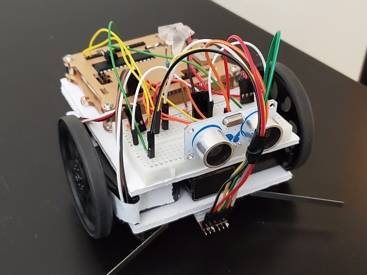
In this post, I’ll show you how to add sound to a wheeled robot.

Shout out to the late Gordon McComb for this project idea. He is the author of an excellent book that I recommend buying if you’re getting started with robotics: How to Make a Robot.

Requirements

Here are the requirements:

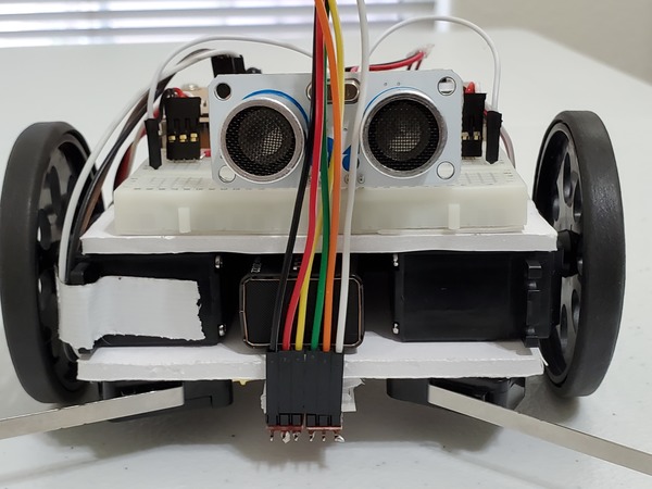
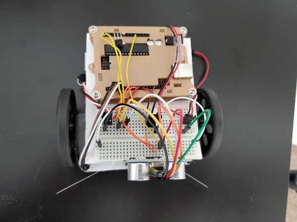
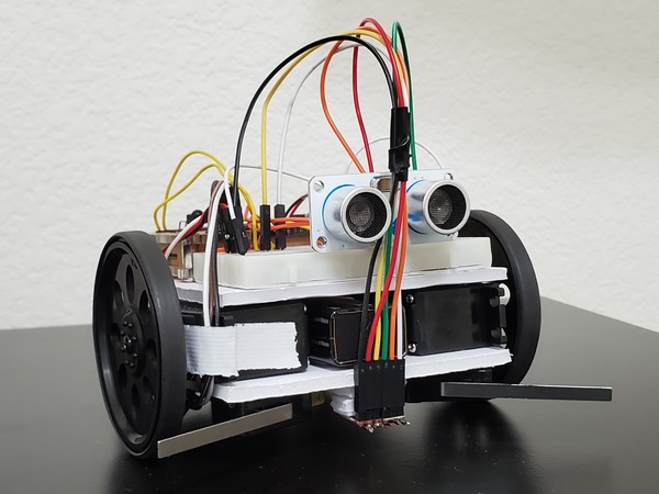
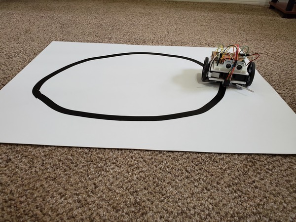
  • Build a wheeled robot that makes sound before it backs up.

You Will Need

The following components are used in this project. You will need:

Directions

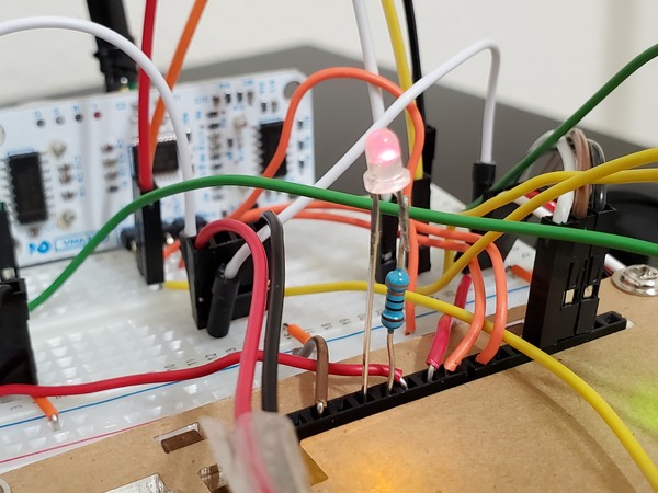
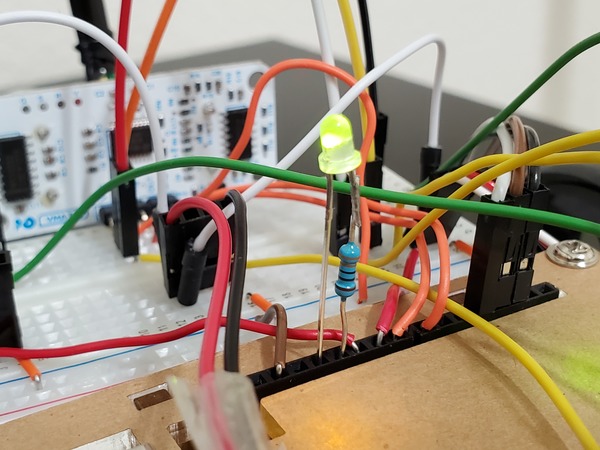
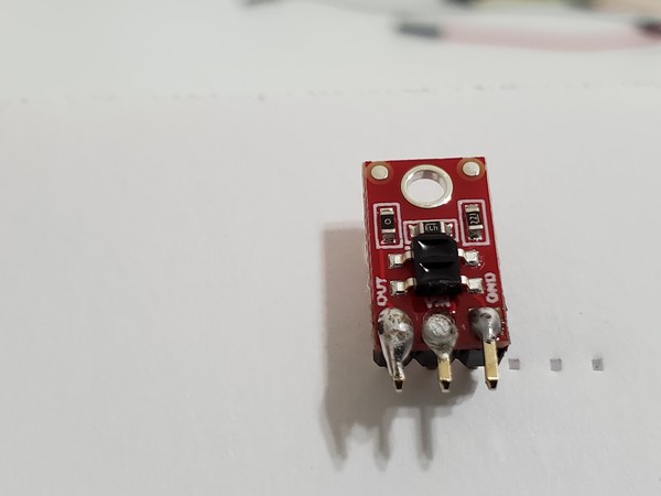
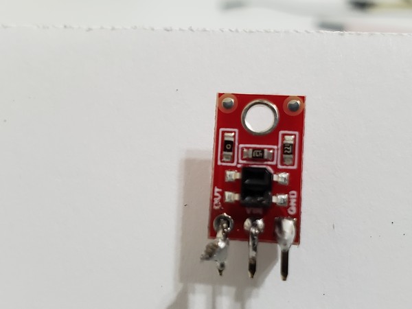
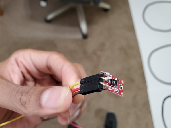
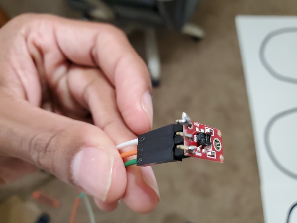
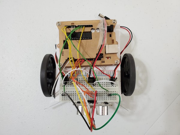
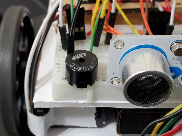
Get the Piezo Transducer.

Stick the positive lead of the transducer into cell j26. Stick the other lead of the transducer into cell j29.

Connect digital pin 5 of the Arduino board to cell f26 of the breadboard.

Connect f29 to e29 with a male to male jumper wire, or just make sure that j29 is electrically connected to Ground.

sound-robot

Upload the following sketch to the Arduino breadboard to test the Piezo transducer.

#define SPKR 5

/**
 * Test the piezo transducer 
 * connected to pin 5
 * 
 * @author Addison Sears-Collins
 * @version 1.0 2019-05-15
 */
 
void setup() {
}

// Play sounds over and
// over again
void loop() {
   tone(SPKR, 247, 300); //247 Hz, 300ms
   delay(200);
   tone(SPKR, 131, 300);
   delay(200);
   tone(SPKR, 1175, 300);
   delay(200);
   tone(SPKR, 262, 300);
   delay(200);
   tone(SPKR, 1175, 300);
   delay(200);
   tone(SPKR, 131, 300);
   delay(200);
   tone(SPKR, 262, 300);
   delay(200);
   tone(SPKR, 1175, 300);
   delay(200);
   tone(SPKR, 247, 300); //247 Hz, 300ms
   delay(200);
}

Upload the following sketch to the Arduino breadboard in order to cause the robot to make sound just before it backs up.

#include <Servo.h> 

/**
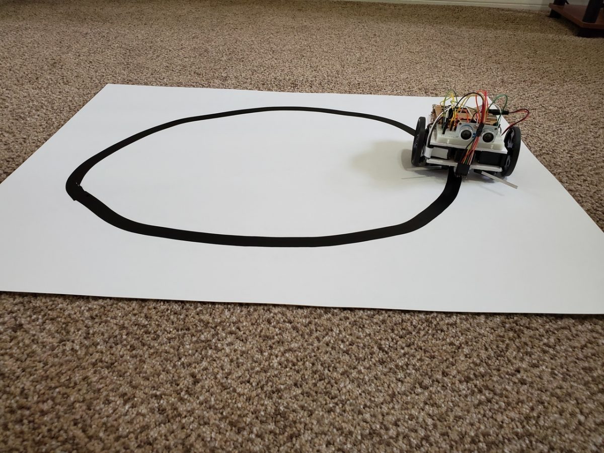
 *  This robot will move around a room and when it 
 *  bumps into an object, it will turn around and 
 *  go in another direction. It will make a noise
 *  just before it backs up.
 * 
 * @author Addison Sears-Collins
 * @version 1.0 2019-05-12
 */

#define SPKR 5

// Create two servo objects, one for each wheel
Servo right_servo;
Servo left_servo;

// Volatile keyword is used because these variables
// can change at any time without any action having been
// taken by the compiled code. 

volatile int left_switch = LOW;   // Left switch flag
volatile int right_switch = LOW;  // Right switch flag
boolean already_started = false;  

/*   
 *  This setup code is run only once, when Arudino is 
 *  supplied with power.
 */
void setup() {
  // Set the pin modes for the switches
  pinMode(2, INPUT); // Right switch is input
  pinMode(3, INPUT); // Left switch is input
  pinMode(4, OUTPUT); // Pin 4 is ground
  
  // Turn on the internal pull up resistors for the switches
  // Keeps input from floating when the switches are not
  // pressed
  digitalWrite(2, HIGH);     // Right switch default to high
  digitalWrite(3, HIGH);     // Left switch default to high
  digitalWrite(4, LOW);      // Pin 4 default is ground

  right_servo.attach(9);      // Right servo is pin 9
  left_servo.attach(10);      // Left servo is pin 10
 
  // Declare the interrupts
  // attachInterrupt(digitalPinToInterrupt(pin), ISR, mode)
  // Interrupt when go from high to low
  attachInterrupt(digitalPinToInterrupt(2), hit_right, FALLING); 
  attachInterrupt(digitalPinToInterrupt(3), hit_left, FALLING);  
  
  already_started = true;  // Bot can now move
}

void loop() {
  if (left_switch == HIGH) {       // If the left switch is hit
    go_backwards();                // Go backwards for one second
    delay(1000); 
    go_right();                    // Turn to the right for one second
    delay(1000);
    go_forward();                  // Move forward
    left_switch = LOW;             // Reset the flag
  }
  
  if (right_switch == HIGH) {      // If the right switch is hit
    go_backwards();                // Go backwards for one second
    delay(1000); 
    go_left();                     // Turn left for one second
    delay(1000);
    go_forward();                  // Move forward
    right_switch = LOW;            // Reset the flag
  }
}
  
// Interrupt routine for left switch bumping into an object
void hit_left() {
  if (already_started)              // Valid if the program has begun
    left_switch = HIGH;             
}

// Interrupt routine for right switch bumping into an object
void hit_right() {
  if (already_started)              // Valid if the program has begun
    right_switch = HIGH;
}

/*   
 *  Forwards, backwards, right, left, stop.
 */
void go_forward() {
  right_servo.write(0);
  left_servo.write(180);
}
void go_backwards() {

  // Make a noise before you go backwards
  tone(SPKR, 247, 300); //247 Hz, 300ms
  delay(200);
  tone(SPKR, 131, 300);
  delay(200);
  tone(SPKR, 1175, 300);
  delay(200);
  right_servo.write(180);
  left_servo.write(0);
}
void go_right() {
  right_servo.write(180);
  left_servo.write(180);
}
void go_left() {
  right_servo.write(0);
  left_servo.write(0);
}
/*
void stop_all() {
  right_servo.write(90); // Tweak the 90
  left_servo.write(90);  // Tweak the 90
}
*/

How to Add Lights to a Wheeled Robot | Arduino

In this post, I’ll show you how to add lights to a wheeled robot so that the light is red when the robot is moving backwards and is green when the robot is moving forwards.

Shout out to the late Gordon McComb for this project idea. He is the author of an excellent book that I recommend buying if you’re getting started with robotics: How to Make a Robot.

Requirements

Here are the requirements:

  • Add lights to a wheeled robot so that the light is red when the robot is moving backwards and is green when the robot is moving forwards.

You Will Need

The following components are used in this project. You will need:

Directions

Get the bi-color LED.

Cut the shorter lead of the LED so that it is 1/4 inches in length.

Get the 300 Ohm resistor. Cut one of the ends so that it is 3/8 inches.

Solder the short lead of the LED to the short lead of the 300 Ohm resistor.

Cut the bottom of the resistor so that its lead is 3/8 inches in length.

Cut the lead of the LED that is not connected to the resistor so that it is the same length as the lead that has the resistor soldered to it.

Insert the LED into the Arduino board. The lead with the resistor goes into pin 11. The lead that does not have the resistor gets inserted into pin 12.

Upload the following code to the Arduino board. you should see the LED flashing red and green.

/**
 * Make a bi-color LED flash red and green.
 * 
 * @author Addison Sears-Collins
 * @version 1.0 2019-05-15
 */

#define LED_RED 11
#define LED_GREEN 12

/*   
 *  This setup code is run only once, when 
 *  Arudino is supplied with power.
 */
void setup() {
  
  // Define output pins
  pinMode(LED_RED, OUTPUT);  
  pinMode(LED_GREEN, OUTPUT);
 
  // Set output values
  digitalWrite(LED_RED, LOW); 
  digitalWrite(LED_GREEN, LOW);
}

/*   
 *  This code is run again and again to
 *  make the LED blink.
 */
void loop() {
  red_blink();
  green_blink();
}

// Method to blink the red LED
void red_blink() {
  digitalWrite(LED_RED, HIGH);
  delay(250);                          
  digitalWrite(LED_RED, LOW);     
  delay(250);                         
} 

// Method to blink the green LED
void green_blink() {
  digitalWrite(LED_GREEN, HIGH);
  delay(250);                         
  digitalWrite(LED_GREEN, LOW);     
  delay(250);                         
}

Now, upload the following code to the Arduino board. In this code, the LED will flash green when the robot is moving forward, and the LED will flash red when the robot is moving backwards.

#include <Servo.h> 

/**
 * Make a robot whose light is red when the robot 
 * is moving backwards and is green when the robot 
 * is moving forwards.
 * 
 * @author Addison Sears-Collins
 * @version 1.0 2019-05-15
 */


Servo right_servo;
Servo left_servo;

volatile int left_switch = LOW;   // Flag for left switch
volatile int right_switch = LOW;  // Flag for right switch
boolean started = false;     // True after first start

#define LED_RED 11
#define LED_GREEN 12

void setup() {
  // Set pin modes for switches
  pinMode(2, INPUT);
  pinMode(3, INPUT);
  pinMode(4, OUTPUT);
  
  // Set internal pull up resistors for switches
  // These go LOW when pressed as connection
  // is made with Ground.
  digitalWrite(2, HIGH);     // Right switch
  digitalWrite(3, HIGH);     // Left switch
  
  digitalWrite(4, LOW);      // Pin 4 is ground

  right_servo.attach(9);      // Right servo to pin 9
  left_servo.attach(10);      // Left servo to pin 10
 
  // Set up the interrupts
  attachInterrupt(0, bump_right, FALLING);
  attachInterrupt(1, bump_left, FALLING);
  
  started = true;            // OK to start moving
  
  pinMode(LED_GREEN, OUTPUT);
  pinMode(LED_RED, OUTPUT);
  digitalWrite(LED_GREEN, LOW);
  digitalWrite(LED_GREEN, LOW);
}

void loop() {
  if (left_switch == HIGH) {   // If the left switch hit
    go_backwards();            // Go backwards for 0.5 sec
    delay(500); 
    turn_right();              // Spin for 1 second
    delay(1000);
    go_forward();              // Go forward
    left_switch = LOW;         // Reset flag shows bumped
  }
  
  if (right_switch == HIGH) {  // If right switch hit
    go_backwards();
    delay(500); 
    turn_left();
    delay(1000);
    go_forward();
    right_switch = LOW;
  }
}
  
// Interrupt handlers
void bump_left() {
  if (started)              // If robot has begun
    left_switch = HIGH;
}
void bump_right() {
  if (started)             
    right_switch = HIGH;
}

// Motion Routines: forward, backwards, turn, stop
// Continuous servo motor
void go_forward() {
  right_servo.write(0);
  left_servo.write(180);
  led_green();
}
void go_backwards() {
  right_servo.write(180);
  left_servo.write(0);
  led_red();
}
void turn_right() {
  right_servo.write(180);
  left_servo.write(180);
  led_off();
}
void turn_left() {
  right_servo.write(0);
  left_servo.write(0);
  led_off();
}
void stop_all() {
  right_servo.write(90);
  left_servo.write(90);
}

void led_green() {
  digitalWrite(LED_GREEN, HIGH);
  digitalWrite(LED_RED, LOW);      
} 
void led_red() {
  digitalWrite(LED_GREEN, LOW);
  digitalWrite(LED_RED, HIGH);
}
void led_off() {
  digitalWrite(LED_GREEN, LOW);
  digitalWrite(LED_RED, LOW);
}

If for some reason you get a situation where you get the opposite result of what should occur (flashes red when moving forward and green when in reverse), the LED is reversed. Turn it around.

lighted-robot-1
lighted-robot-2

Also, if you are getting a situation where your servos are not moving, it likely means that voltage is insufficient. Changing the location of the servo power wire, the wire that connects the red servo line to the red line of the 4xAA battery pack usually does the trick. If not, get new batteries for the servo.

How to Make an Autonomous Line-Following Robot | Arduino

In this post, I’ll show you how to make an autonomous line-following robot using Arduino and a reflectance sensor.

Shout out to the late Gordon McComb for this project idea. He is the author of an excellent book that I recommend buying if you’re getting started with robotics: How to Make a Robot.

Real-World Applications

Here is a real-world application of a line-following robot. Elon Musk is inside the Tesla factory and describes how one of their robots follows a line in order to navigate across the factory floor.

Requirements

Here are the requirements:

  • Make an autonomous line-following robot using Arduino and a reflectance sensor.

You Will Need

The following components are used in this project. You will need:

Directions

First grab the 0.25 inch thick foam board. Cut it into two 3/8 inch by 3/4 inch pieces.

line-following-robot-1
line-following-robot-2

Glue both pads so that one is on top of the other.

Glue the stack of two pads to the underside of the board so that the middle of the stack is exactly in the center of the lower board.

The stack should be right in between both snap action switches. The front of the stack should be slightly behind the front edge of the board.

line-following-robot-3
line-following-robot-4

Grab the header pins that came with the reflectance sensors. Cut the pin headers so that you have two sets of three pins. One set of three will be for one of the sensors and the other set of three will be for the other sensor.

line-following-robot-5

Insert the short end of the header pins into the reflectance sensors.

line-following-robot-6
line-following-robot-7

Solder the short end of the header pins so that the header pins remain in place. Be careful not to solder big blobs that connect one short pin to another. It is a difficult soldering job because the pins are so close together. Just take your time. No need to hurry.

line-following-robot-8
line-following-robot-9
line-following-robot-10
line-following-robot-11
line-following-robot-12

Now grab the following 6 male-to-female jumper wires and hook up the female part as follows:

  • Black, red, yellow (Right sensor)
  • Green, orange, white (Left sensor)
line-following-robot-13
line-following-robot-14

Get a piece of double-sided tape and attach the sensor to the underside of the board on top of small foam board stack.

The front of the sensor should be aligned with the front of the robot.

line-following-robot-15
line-following-robot-16
line-following-robot-17

Connect the 6 male-to-female jumper wires to the breadboard as follows:

  • White wire connects to c23
  • Orange wire connects to h12
  • Green wire connects to GND via h5.
  • Yellow wire connects to c25
  • Red wire connect to g12
  • Black wire connects to GND via h29
  • Connect a wire from a23 to analog pin 4 on the Arduino
  • Connect a wire from a25 to analog pin 5 on the Arduino
line-following-robot-18
line-following-robot-19

If you have issues with the servos not moving, try connecting the ground on the reflectance sensor (the green and black wires) to their own ground on the Arduino.

Upload the following code to the Arduino board to test the reflectance sensors.

/**
 * This is a test of the reflectance
 * sensor of the line following robot.
 * 
 * @author Addison Sears-Collins
 * @version 1.0 2019-05-15
 */

#define line_left A4 // The IO pins connected to sensor
#define line_right A5

int irleft_reflect = 0; // Readings stored here
int irright_reflect = 0;

/*   
 *  This setup code is run only once, when 
 *  Arudino is supplied with power.
 */
void setup() { 
   Serial.begin (9600); // Set the baud rate
} 


/*
 * This is the main code that runs again and again while
 * the Arduino is connected to power.
 */
void loop() { 

  // Read the reflectance sensors
  // Values range from 0 to 1023, representing
  // analog voltage from 0 to 5 volts
  // 0 = solid white; 1023 = solid black
  irleft_reflect = analogRead(line_left);
  irright_reflect = analogRead(line_right);

  Serial.print ("Left:");      
  Serial.print ("\t");        
  Serial.print (irleft_reflect);
  Serial.print ("\t");
  Serial.print ("Right:");
  Serial.println (irright_reflect);
  
  delay(100);
}

Open the Serial Monitor to verify that the values are changing when you wave an object in front of the sensors.

Feel free to close down the Serial Monitor at this stage. We will now make the line course that the robot will follow.

Grab the white poster (22 inches by 28 inches), and also get the 0.75 inch black electrical tape.

Create a course that looks something like the image below. Be sure to keep at least a three-inch margin between the side of the poster board and the line course. Make sure the turns and the course are smooth, otherwise you will have problems.

line-following-robot-20

The course is ready, so upload the following sketch to the Arduino.

#include <Servo.h> // We are using servos, so add library

/**
 * This robot follows a line made with black electric
 * tape on white poster board.
 * 
 * @author Addison Sears-Collins
 * @version 1.0 2019-05-15
 */

// Each servo is an object with its own data and behavior
Servo left_servo;
Servo right_servo;

// Sensors connected to analog pins 4 (left sensor) and 5 (right sensor)
const int left_line = A4;
const int right_line = A5;

// Store sensor readings here
int irleft_reflect = 0;
int irright_reflect = 0;

// Try values between 400 and 800. 
// Helps determine if robot is over the line
int threshold = 800;           

/*   
 *  This setup code is run only once, when 
 *  Arudino is supplied with power.
 */
void setup() { 
  // Assign each servo to its own digital pin on the Arduino
  right_servo.attach(9);  
  left_servo.attach(10); 
} 

void loop() { 

  // Read the reflectance sensors
  irleft_reflect = analogRead(left_line);  
  irright_reflect = analogRead(right_line);

  // robot is right over the line
  if (irleft_reflect >= threshold && irright_reflect >= threshold) {
    line_forward();   
  }

  // robot is veering off to the right
  if (irleft_reflect >= threshold && irright_reflect <= threshold) {
    line_left_slip();  
    delay(4);
  }

  // robot is veering off to the left
  if (irleft_reflect <= threshold && irright_reflect >= threshold) {
    line_right_slip();  
    delay(4);
  }

  // If robot has lost the line, go find it
  if (irleft_reflect < threshold && irright_reflect < threshold) {
    line_right_spin();
    delay(20);
  }
}

// On the continuous rotation servo, the write() 
// method sets the speed of the servo.
// 0 is full speed in one direction.
// 180 is full speed in the other direction.
// ~90 is no movement (You will have to tweak to
//   get no movement).
void line_forward() {
  right_servo.write(0);  
  left_servo.write(180);
}
void line_right_slip() {
  right_servo.write(90);  
  left_servo.write(180);
}
void line_left_slip() {
  right_servo.write(0);  
  left_servo.write(90);
}
void line_right_spin() {
right_servo.write(180);  
  left_servo.write(180);
}
void line_left_spin() {
  right_servo.write(0);  
  left_servo.write(0);
}

Disconnect the USB cable from the Arduino, and place the Arduino on the floor.

Turn on the servos:

  • a13 to e3 = left servo ON
  • e13 to e28 = right servo ON
line-following-robot-25

Plug in the Arduino’s power.

Press the Reset button on the Arduino as you position the robot over the black electrical tape on the course. The Reset button is like unplugging the Arduino and plugging it in again.

Watch the robot in action!

line-following-robot-21-1
line-following-robot-22-1
line-following-robot-24-1
line-following-robot-27

Video