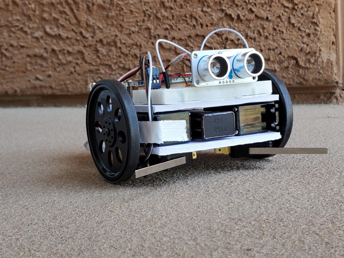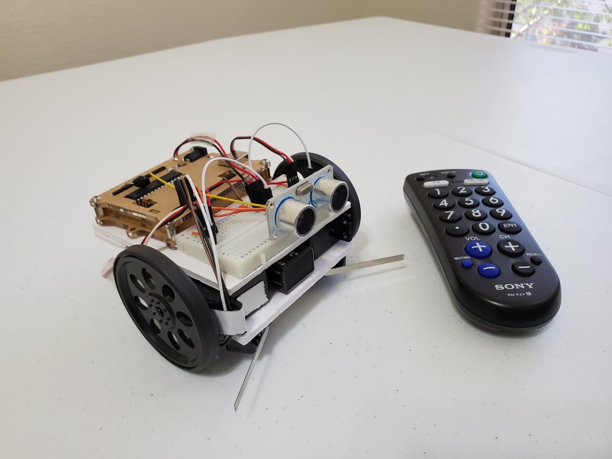
In this post, I’ll show you how to make a remote controlled robot using Arduino and a Sony Universal Remote Control.
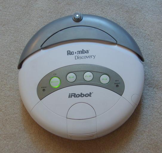
Shout out to the late Gordon McComb for this project idea. He is the author of an excellent book that I recommend buying if you’re getting started with robotics: How to Make a Robot.
Requirements
Here are the requirements:
- Control a wheeled robot using a Sony Universal Remote Control.
You Will Need
The following components are used in this project. You will need:
Directions
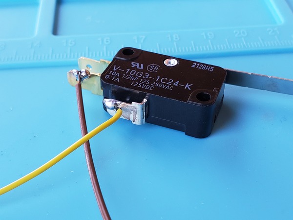
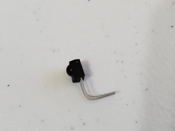
First, get the infrared sensor. Bend the metal lead 0.25 inches below the base of the square sensor so that it makes a 90-degree angle.
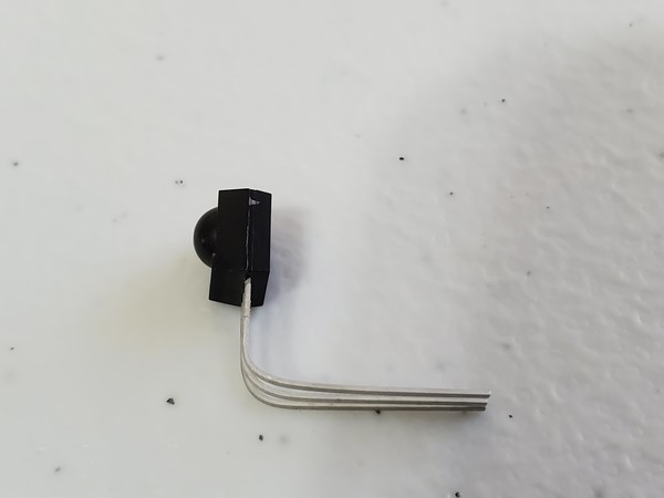
Cut the lead 3/8 inches below the point of the bend. The dome of the sensor should face the opposite direction of the 90-degree bend.
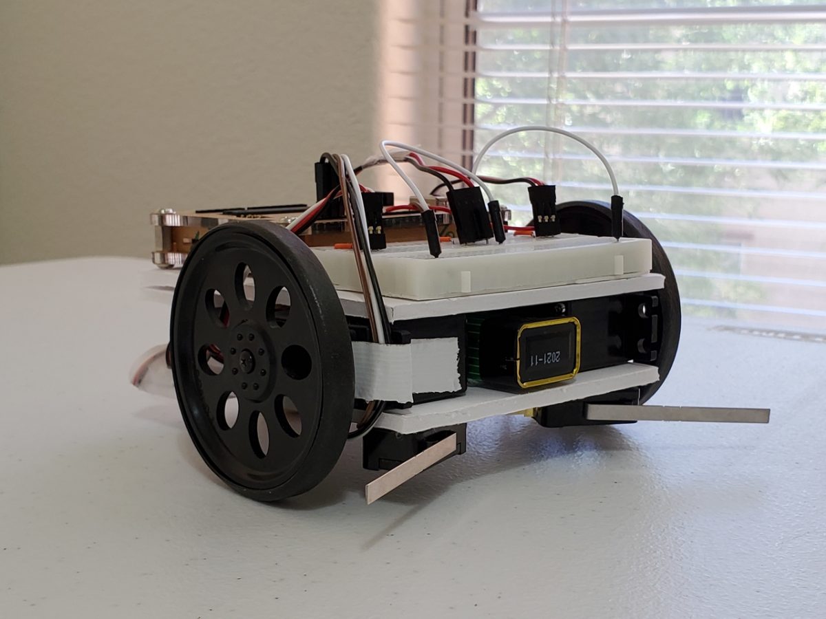
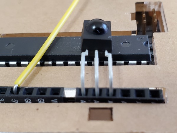
Insert the infrared sensor into the Arduino board so that the pins are inside analog pins 0, 1, and 2. The dome of the infrared sensor should face upwards.
Insert batteries into the Sony Universal remote control.
Set up the remote control so that it can operate a Sony television. The instructions for how to setup the remote control should be included inside the package that it came with.
Add the IRremote library to the Arduino IDE. Go to Sketch -> Include Library -> Manage Libraries and look for “IRremote.” Add it, and then restart the IDE.
Upload the IRtest sketch to the Arduino (see code below). This sketch will be used to test the remote control, whose buttons do the following:
- 1: Left Turn (Forward)
- 2: Forward
- 3: Right Turn (Forward)
- 4: Spin Left
- 5: Stop
- 6: Spin Right
- 7: Left Turn (Reverse)
- 8: Backwards
- 9: Right Turn (Reverse)
Open the Serial Monitor, and press any number from 1 to 9. You should see that number show up in the Serial Monitor.
#include <IRremote.h>

/**
 * This code tests the Sony Universal Remote Control
 *
 * Credit: Gordon McComb, How to Make a Robot.
 * Book available here: https://amzn.to/2Q303ed
 *
 * Code was modified by Addison Sears-Collins
 */

#define  show_code  false   // Test mode
                            // false means match to # buttons
                            // true means display raw code

const int RECV_PIN = A0;     // Receiver input on Analog 0
IRrecv irrecv(RECV_PIN);     // Define IR recever object
decode_results results;

/*
 *  This setup code is run only once, when
 *  Arudino is supplied with power.
 */
void setup() {
  pinMode(A1, OUTPUT);       // IR power, ground pins
  pinMode(A2, OUTPUT);
  digitalWrite(A1, LOW);     // The ground for the IR
  digitalWrite(A2, HIGH);    // Power to the IR
  irrecv.enableIRIn();       // Initiate the receiver
  Serial.begin(9600);        // Set the baud rate
}

void loop() {

  if (irrecv.decode(&results)) {  // If valid value was received
    if(show_code) {                // If show_code=true
      Serial.print("0x");
      Serial.println(results.value, HEX);  // Display raw hex
    } else {                      // else show_code=false
      switch (results.value) {    // Match button to Sony codes
        case 0x10:
          Serial.println("1");
          break;
        case 0x810:
          Serial.println("2");
          break;
        case 0x410:
          Serial.println("3");
          break;
        case 0xC10:
          Serial.println("4");
          break;
        case 0x210:
          Serial.println("5");
          break;
        case 0xA10:
          Serial.println("6");
          break;
       case 0x610:
          Serial.println("7");
          break;
        case 0xE10:
          Serial.println("8");
          break;
        case 0x110:
          Serial.println("9");
          break;
      }
    }
    irrecv.resume();    // Receive the next value
    delay(10);          // Pause for 10 milliseconds
  }

}
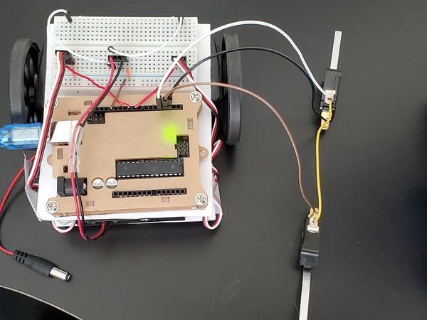
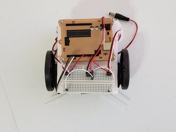
Now, upload the code below to the Arduino. Remove the USB cord. Place the robot on the floor. Turn on the servos. Insert the 9V battery jack into the Arduino, and drive the robot around the room!
#include <Servo.h>

/**
 * This code runs the remote controlled robot
 *
 *
 * @author Addison Sears-Collins
 * @version 1.0 2019-05-14
 */

Servo left_servo;              // Define left servo
Servo right_servo;             // Define right servo

#include <IRremote.h>
int RECV_PIN = A0;
IRrecv irrecv(RECV_PIN);
decode_results results;
volatile int active_left = LOW;
volatile int active_right = LOW;
boolean started = false;

void setup() {
  // Set pin modes for switches
  pinMode(2, INPUT);
  pinMode(3, INPUT);
  pinMode(4, OUTPUT);
  digitalWrite(2, HIGH);
  digitalWrite(3, HIGH);
  digitalWrite(4, LOW);     // Serves as ground connection

  pinMode(A1, OUTPUT);       // IR power, ground pins
  pinMode(A2, OUTPUT);
  digitalWrite(A1, LOW);     // IR ground
  digitalWrite(A2, HIGH);    // IR power

  right_servo.attach(9);    // Set right servo to digital pin 9
  left_servo.attach(10);    // Set left servo to digital pin 10
  irrecv.enableIRIn();     // Start the receiver

  Serial.begin(9600);

  // Set up interrupts
  attachInterrupt(0, bump_right, FALLING);
  attachInterrupt(1, bump_left, FALLING);

  started = true;
}

void loop() {

  if (active_left == HIGH) {           // If left bumper hit
    go_backwards();
    delay(500);
    spin_right();
    delay(1000);
    go_forward();
    active_left = LOW;
    Serial.println("active_left");
  }

  if (active_right == HIGH) {          // If right bumper hit
    go_backwards();
    delay(500);
    spin_left();
    delay(1000);
    go_forward();
    active_right = LOW;
    Serial.println("active_right");
  }

  if (irrecv.decode(&results)) {
    switch (results.value) {
      case 0x10:
        Serial.println("1");     // Turn left forward
        left_turn_fwd();
        break;
      case 0x810:
        Serial.println("2");     // Forward
        go_forward();
        break;
      case 0x410:
        Serial.println("3");     // Turn right forward
        right_turn_fwd();
        break;
      case 0xC10:
        Serial.println("4");    // Spin left
        spin_left();
        break;
      case 0x210:
        Serial.println("5");    // Stop
        stop_all();
        break;
      case 0xA10:
        Serial.println("6");    // Spin right
        spin_right();
        break;
     case 0x610:
        Serial.println("7");    // Turn left reverse
        left_turn_backwards();
        break;
      case 0xE10:
        Serial.println("8");    // Reverse
        go_backwards();
        break;
      case 0x110:
        Serial.println("9");    // Turn right reverse
        turn_right_backwards();
        break;
    }
    irrecv.resume(); // Receive the next value
    delay(2);
  }
}

// Routines for forward, reverse, turns, and stop
void go_forward() {
  left_servo.write(180);
  right_servo.write(0);
}
void go_backwards() {
  left_servo.write(0);
  right_servo.write(180);
}
void spin_right() {
  left_servo.write(180);
  right_servo.write(180);
}
void spin_left() {
  left_servo.write(0);
  right_servo.write(0);
}
void right_turn_fwd() {
  left_servo.write(180);
  right_servo.write(90);
}
void left_turn_fwd() {
  left_servo.write(90);
  right_servo.write(0);
}
void left_turn_backwards() {
  left_servo.write(90);
  right_servo.write(180);
}
void turn_right_backwards() {
  left_servo.write(0);
  right_servo.write(90);
}
void stop_all() {
  left_servo.write(90);
  right_servo.write(90);
}

// Interrupt service routines
void bump_left() {
  if (started)
    active_left = HIGH;
}
void bump_right() {
  if (started)
    active_right = HIGH;
}