How To Install Ubuntu and Raspbian on Your Raspberry Pi 4

In this tutorial, we will set up a Raspberry Pi 4 with both the Ubuntu 20.04 and Raspbian operating systems.

You Will Need

2020-08-29-150822

This section is the complete list of components you will need for this project.
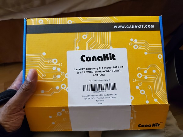
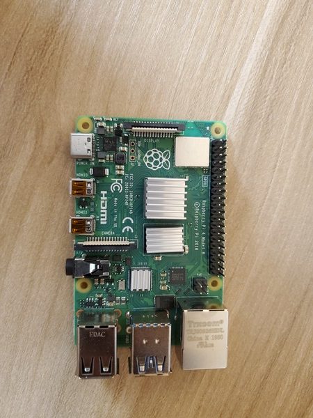
Install Ubuntu

Prepare the SD Card

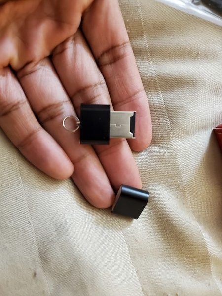
Grab the USB MicroSD Card Reader.

2020-08-29-151538

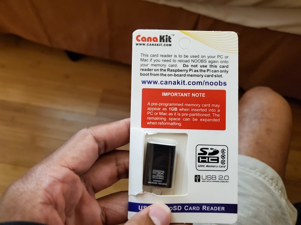
Take off the cap of the USB MicroSD Card Reader.

2020-08-29-151621

Stick the MicroSD card inside the Card Reader.

Stick the Card Reader into the USB drive on your computer.

Download the Raspberry Pi Imager for your operating system. I’m using Windows, so I will download Raspberry Pi Imager for Windows.

Open the Raspberry Pi Imager. Follow the instructions to install it on your computer.

When the installation is complete, click Finish.

Open the CHOOSE OS menu.

Scroll down, and click “Ubuntu”.

Select the Ubuntu 20.04 download (32-bit server).

Click CHOOSE SD. 

Select the microSD card you inserted. 

Click WRITE, and wait for the operating system to write to the card. It will take a while so be patient.

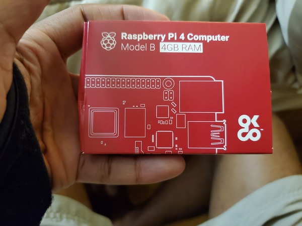
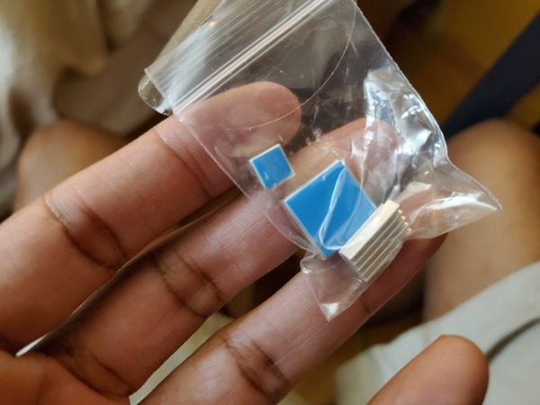
While you’re waiting, grab your Raspberry Pi 4 and the bag of heat sinks.

2020-08-29-154338
2020-08-29-154824

Peel off the backup of the heat sinks, and attach them to the corresponding chips on top of the Raspberry Pi.

2020-08-29-154344

Grab the cooling fan.

2020-08-29-155325

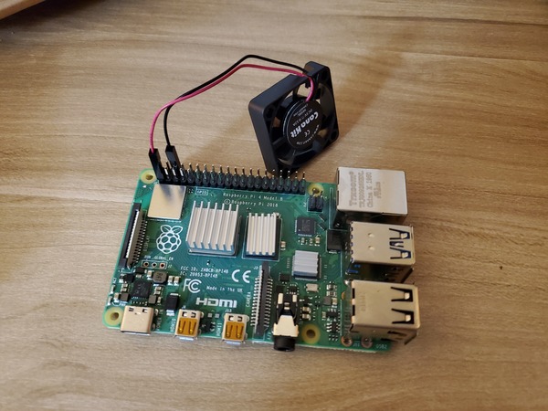
Connect the black wire to header pin 6 of the Raspberry Pi. Connect the red wire to header pin 1 of the Raspberry Pi.

2020-08-29-155750

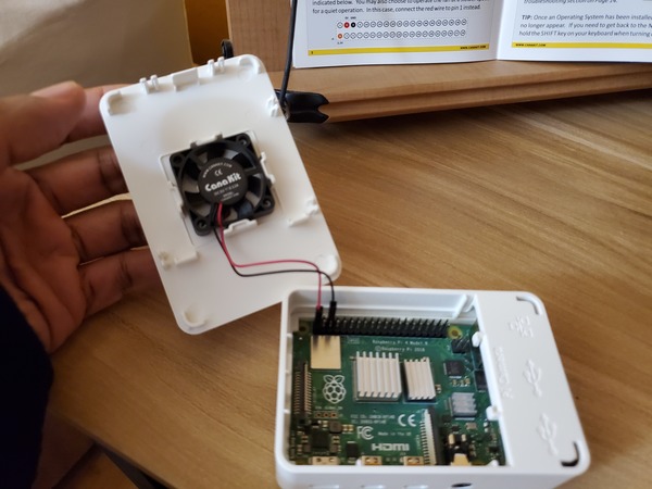
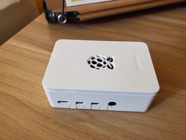
Install the Raspberry Pi inside the case.

2020-08-29-155840

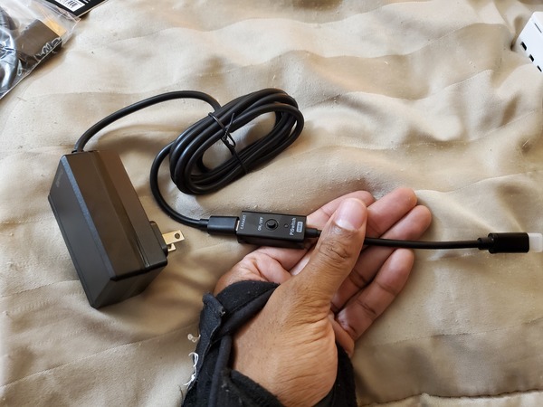
Connect the PiSwitch to the USB-C Power Supply. It should snap into place.

2020-08-29-160447

Once the installation of the operating system is complete, remove the microSD card reader from your laptop.

Set Up Wi-Fi

Reinsert the microSD card into your computer.

2020-08-29-161429

Open your File Manager, and find the network-config file. Mine is located on the F drive in Windows.

Open that file using Notepad or another plain text editor.

Uncomment (remove the “#” at the beginning) and edit the following lines to add your Wi-Fi credentials (don’t touch any of the other lines):

wifis:
  wlan0:
  dhcp4: true
  optional: true
  access-points:
    <wifi network name>:
      password: "<wifi password>"

For example:

wifis:
  wlan0:
  dhcp4: true
  optional: true
  access-points:
    "home network":
      password: "123456789"

Make sure the network name and password are inside quotes.

Save the file.

Set Up the Raspberry Pi

Safely remove the microSD Card Reader from your laptop.

Remove the microSD card from the card reader.

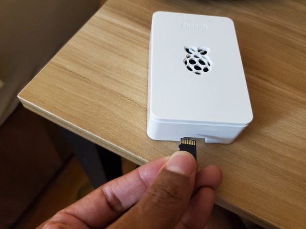
Insert the microSD card into the bottom of the Raspberry Pi.

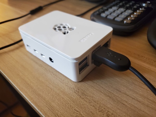
Connect a keyboard and a mouse to the USB 3.0 ports of the Raspberry Pi.

2020-08-29-165525

Connect an HDMI monitor to the Raspberry Pi using the Micro HDMI cable connected to the Main MIcro HDMI port (which is labeled HDMI 0).

Connect the 3A USB-C Power Supply to the Raspberry Pi. You should see the computer boot.

Log in using “ubuntu” as both the password and login ID. You will have to do this multiple times.

You will then be asked to change your password.

Type:

sudo reboot

Type the command: 

hostname -I 

You will see the IP address of your Raspberry Pi. Mine is 192.168.254.68. Write this number down on a piece of paper because you will need it later.

Now update and upgrade the packages.

sudo apt update
sudo apt upgrade

Now, install a desktop.

sudo apt install xubuntu-desktop

Installing the desktop should take around 20-30 minutes or so.

Once that is done, it will ask you what you want as your default display manager. I’m going to use gdm3.

Wait for that to download.

Reboot your computer.

sudo reboot

Your desktop should show up.

Type in your password and press ENTER.

Click on Activities in the upper left corner of the screen to find applications.

If you want to see a Windows-like desktop, type the following commands:

cd ~/.cache/sessions/

Remove any files in there.

Type:

rm 

Then press the Tab key and press Enter.

Now type:

xfdesktop

Connect to Raspberry Pi from Your Personal Computer

Follow the steps for Putty under step 9b at this link to connect to your Raspberry Pi from your personal computer.

Install Raspbian

Now, we will install the Raspbian operating system. Turn off the Raspberry Pi, and remove the microSD card.

Insert the default microSD card that came with the kit.

Turn on the Raspberry Pi.

You should see an option to select “Raspbian Full [RECOMMENDED]”. Click the checkbox beside that.

Change the language to your desired language.

Click Wifi networks, and type in the password of your network.

Click Install.

Click Yes to confirm.

Wait while the operating system installs.

You’ll get a message that the operating system installed successfully.

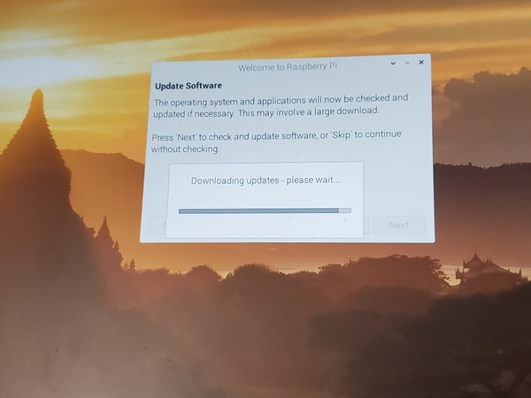
Now follow all the steps from Step 7 of this tutorial. All the software updates at the initial startup take a really long time, so be patient. You can even go and grab lunch and return. It might not look like the progress bar is moving, but it is.

2020-08-29-212546

Keep building!

How to Control a Servo Motor Using Arduino

Motors are what enable robots to move and do things. Without motors, robots are just big pieces of metal and plastic that can’t move.

The simplest type of motor is the direct current (DC) motor. This type of motor spins around and around in one direction, rotating 360 degrees. It only stops rotating when it is disconnected from a power source. DC motors are common in wheeled robots.

Another type of motor is known as the servo motor (“servo”). Instead of rotating continuously for 360 degrees in one direction, servo motors move to specific angles, typically anything between 0 and 180 degrees. Servo motors are common in robotics. You will see them in all types of applications where a motor needs to move a part of the robot to a specific position. Examples include robot arms, hands, legs, and humanoid robots. NASA’s Robonaut 2, for example, has a total of 54 servo motors which are used to move the robot’s joints, head, and other body parts.

In this post, I will explain how servos work, and then we will get our hands dirty by powering up our Arduino and using it to control a servo.

How Servos Work

Servos work by receiving electrical signals. The length of this signal controls the angle the motor turns…the longer the signal, the greater the motor will turn. This process is known as pulse-width-modulation because the width (i.e. duration) of the electrical pulse modulates (modifies) the motor’s angle of rotation. Here is what that looks like:

controlling-a-servo-motor-2

Requirements

Here are the requirements:

  • Control a servo motor’s angle of rotation.

You Will Need

controlling-a-servo-motor-1

The following components are used in this project. You will need:

Directions

Control a Servo Using Arduino’s Power Supply

controlling-a-servo-motor-3

Here is the hardware we need to set up:

servo-motor-arduino

Connect the red wire of the servo to the 5V pin of the Arduino Uno.

Connect the black wire of the servo to the GND (ground) pin of the Arduino Uno.

Connect the yellow control wire of the servo to Digital Pin 9 of the Arduino Uno. This yellow wire is the one that will receive commands from the Arduino. Pin 9 is one of Arduino’s Pulse-Width Modulation pins.

Power up your Arduino by plugging in the USB cord to your computer.

Open the Arduino IDE, and in a new sketch, write the following code:

/* Sweep
 by BARRAGAN <http://barraganstudio.com>
 This example code is in the public domain.

 modified 8 Nov 2013
 by Scott Fitzgerald
 http://www.arduino.cc/en/Tutorial/Sweep
*/

#include <Servo.h>

Servo myservo;  // create servo object to control a servo
// twelve servo objects can be created on most boards

int pos = 0;    // variable to store the servo position

void setup() {
  myservo.attach(9);  // attaches the servo on pin 9 to the servo object
}

void loop() {
  for (pos = 0; pos <= 180; pos += 1) { // goes from 0 degrees to 180 degrees
    // in steps of 1 degree
    myservo.write(pos);              // tell servo to go to position in variable 'pos'
    delay(15);                       // waits 15ms for the servo to reach the position
  }
  for (pos = 180; pos >= 0; pos -= 1) { // goes from 180 degrees to 0 degrees
    myservo.write(pos);              // tell servo to go to position in variable 'pos'
    delay(15);                       // waits 15ms for the servo to reach the position
  }
}

Upload the code to your board. This code will make the shaft of the motor sweep back and forth 180 degrees.

Control a Servo Using Arduino and a Potentiometer

controlling-a-servo-motor-4

In some applications, we might want to control the angle a servo rotates without having to constantly modify the code. One way to do this is to use a potentiometer. Think of a potentiometer as a variable resistor. By turning the knob, you can control the voltage output of the potentiometer.

In this piece of the project, we will set up software that reads the voltage output of the potentiometer. It then converts that number it into an angle for the servo.

A potentiometer has 3 terminals:

  1. Two outer terminals are used for power: one outer pin connects to ground and the other connects to positive voltage. Potentiometers don’t have polarity, so it doesn’t matter which one is ground and which one is connected to positive voltage.
  2. A central control terminal is used for voltage output: turning the knob of the potentiometer increases or decreases the resistance, which lowers or increases the voltage output.

So let’s set all this up. Here is the schematic diagram:

servo-motor-arduino-potentiometer

With your Arduino unplugged, stick the 10k Ohm potentiometer into the solderless breadboard. Make sure each terminal is connected to separate row in the breadboard.

Connect one of the outer terminals to the blue (ground) rail of the breadboard.

Connect the other outer terminal to the red (positive) rail of the breadboard.

Connect the central pin of the potentiometer to Analog Input pin A0 of the Arduino.

Connect the black and red wires of the servo to the blue and red rail of the breadboard, respectively.

Connect the yellow control wire to pin 9 of the Arduino.

Connect a wire from the +5V pin of the Arduino to the positive red rail of the breadboard.

Connect a wire from Ground (GND) of the Arduino to the blue rail of the breadboard.

This completes the hardware setup.

Plug in the Arduino.

controlling-a-servo-motor-5

Open up the IDE. Inside a new sketch, write the following code:

/*
 Controlling a servo position using a potentiometer (variable resistor)
 by Michal Rinott <http://people.interaction-ivrea.it/m.rinott>

 modified on 8 Nov 2013
 by Scott Fitzgerald
 http://www.arduino.cc/en/Tutorial/Knob
*/

#include <Servo.h>

Servo myservo;  // create servo object to control a servo

int potpin = 0;  // analog pin used to connect the potentiometer
int val;    // variable to read the value from the analog pin

void setup() {
  myservo.attach(9);  // attaches the servo on pin 9 to the servo object
}

void loop() {
  val = analogRead(potpin);            // reads the value of the potentiometer (value between 0 and 1023)
  val = map(val, 0, 1023, 0, 180);     // scale it to use it with the servo (value between 0 and 180)
  myservo.write(val);                  // sets the servo position according to the scaled value
  delay(15);                           // waits for the servo to get there
}

Upload the code to your board.

Turn the knob on your potentiometer to move the servo.

Your Arduino microcontroller is reading the voltage that is coming in from the potentiometer on Analog Input pin 0. It is then converting this voltage into a value between 0 and 180. This degree value then gets sent down the yellow control wire to the servo, and the servo moves accordingly. Thus, the higher the voltage output by the potentiometer, the greater the servo’s angle of rotation.

Control a Servo Using an External Power Supply

controlling-a-servo-motor-6

We don’t always want to use the Arduino to power our servos. Sometimes we might want to use an external power supply. Here is a basic schematic (Note: Ignore the AAA on the batteries below. They are actually AA.):

servo-motor-arduino-external-power

The biggest change from the previous implementation is that now the servos are connected to the 4xAA battery holder instead of the Arduino’s power supply.

With your Arduino powered off, move the red and black wires of the servo to the other red and blue rails of your solderless breadboard.

Connect the red wire of the 4xAA battery holder to the red rail of the solderless breadboard (the one electrically connected to the servo).

Connect the black wire of the 4xAA battery holder to the blue rail of the breadboard.

Make sure your external power supply is connected to the same ground as the Arduino. Use a male-to-male jumper wire to connect both ground rails. This is called common ground.

Power up the Arduino, open the IDE, and find the same sketch as the previous section of this blog post.

Upload the sketch to your Arduino.

Turn the knob of the potentiometer, and watch the servo move.

How to Configure Raspberry Pi to Run Programs On Startup

In this post, I’ll show you how to configure your Raspberry Pi so that your programs can run as soon as you plug in your Raspberry Pi to a power source.

Requirements

Here are the requirements:

  • Run a program as soon as the Raspberry Pi is turned on.

Directions

Power up your Raspberry Pi, and open up a terminal window.

Type:

sudo nano /etc/rc.local

Scroll down the file to the area right after fi but before exit 0. Type:

python3 /home/pi/robot/ball_following_yellow.py &

The format is

python3 /your/file/path/here/filename.py &

Press CTRL-X, and save the file.

Restart your Raspberry Pi.

sudo reboot

Your program, ball_following_yellow.py, should run on startup.