What is the tf2 Library?
In this section, we will work with the ROS tf2 (Transform) library. The tf2 library was created to provide a way to keep track of the different coordinate frames in a robotic system.
A typical robotic system has multiple 3D coordinate frames. Consider a robotic arm for example. You have the world coordinate frame, and then each joint of the arm has its own coordinate frame.
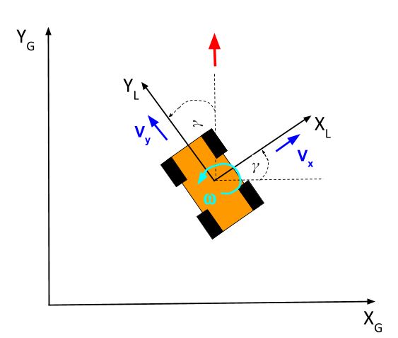
In this 2D robotic car example, you can see we have two coordinate frames. There is the global (i.e. world) coordinate frame. There is also the local coordinate frame (i.e. the car’s perspective).
Why are coordinate frames important in robotics? Well imagine you have a robot on an assembly line picking up objects as they pass by. A camera that is overhead identifies an object that needs to be picked up. How does the robot know where to move its gripper so that it can pick up the object?
The system needs to translate the object’s position (i.e. coordinates) in the camera coordinate frame to a position in the gripper coordinate frame.
You can see now how the tf library in ROS can really come in handy when you have lots of sensors and actuators that need to work together to perform a task.
And that’s not all. The coordinate frames change with time as the robot moves in the world. The tf library can help with this too.
Let’s complete the official ROS tutorials on the tf2 library.
First, let’s check out the demo to see the tf2 library in action.
Start by downloading the required ROS packages from the ROS repository. Open a new terminal window, and type these commands:
cd ~/catkin_ws/src
sudo apt-get update
sudo apt-get install ros-noetic-turtle-tf2 ros-noetic-tf
sudo apt-get install ros-noetic-tf2-tools
To run the demo, open a new terminal, and type this command:
roslaunch turtle_tf2 turtle_tf2_demo.launch
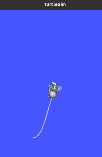
You should see a turtle on your screen.
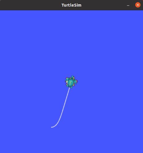
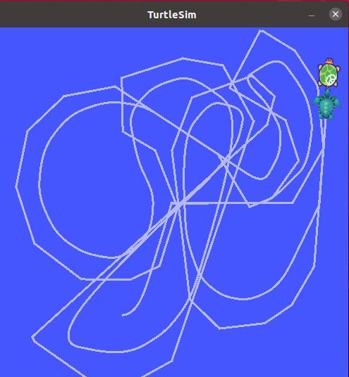
Click the terminal window where you executed the roslaunch command, and then use the arrow keys to move the turtle around the screen.
You should see a turtle that is trailing the turtle that you are driving around the screen.
This demo uses the tf2 library to generate three coordinate frames:
- World frame
- Turtle1 frame
- Turtle2 frame
A tf2 broadcaster is publishing the coordinate frames of the lead turtle. A tf2 listener calculates the difference between the coordinate frames of the lead turtle and the follower turtle. It then moves the follower turtle so that it follows the lead turtle.
Let’s take a look at what is going on behind the scenes.
In a new terminal window, type the following commands:
rosrun tf2_tools view_frames.py
evince frames.pdf
Evince is a document viewer for pdf files.
You can see below the tree of how the coordinate frames are connected:
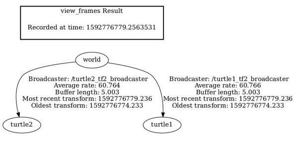
The world coordinate frame is the parent of the turtle1 and turtle1 coordinate frames.
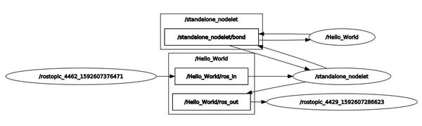
To see real-time information of the tree of coordinate frames, you can type this command:
rosrun rqt_tf_tree rqt_tf_tree
Now, open a new terminal window, and type this command:
rosrun tf tf_echo [reference_frame] [target_frame]
To see the transformation between any two frames, you can use this syntax:
rosrun tf tf_echo [reference_frame] [target_frame]
Type this command:
rosrun tf tf_echo turtle1 turtle2
Now, let’s look at the relationship between the coordinate frames using rviz. rviz is a 3D visualizer for ROS
rosrun rviz rviz -d `rospack find turtle_tf2`/rviz/turtle_rviz.rvizOn the left panel, click the arrow next to TF, and check all the boxes.
Click Select and highlight all the coordinate frames in the image. You should see boxes that define the different frames.
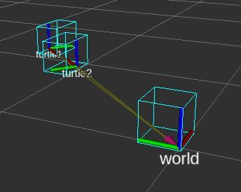
As you drive the turtle around, you will see those coordinate frames move.
Press CTRL+C on all terminal windows to shut everything down.
Now that we’ve looked at the demo, let’s take a few steps back and see how we can write the tf2 broadcaster (that publishes/broadcasts the coordinate frames of a robot) and tf2 listener (that receives and uses the coordinate frame information) that made this demo possible.
First, we’ll go through the process for C++. Then we’ll do the process for Python.
How to Write a tf2 Static Broadcaster in C++
The tf2 static broadcaster is used when you have a robotic system that is static (i.e. doesn’t change position and orientation that frequently). We won’t try to reproduce the turtle simulation just yet. We’ll begin to do that in the next section.
The first thing you want to do is open up a new terminal window and create a new catkin package.
cd ~/catkin_ws/src
catkin_create_pkg learning_tf2 tf2 tf2_ros roscpp rospy turtlesim
Move into the src folder of the package we just made.
roscd learning_tf2/src
Open up a new C++ file named static_turtle_tf2_broadcaster.cpp.
gedit static_turtle_tf2_broadcaster.cpp
Type the following code inside it.
#include <ros/ros.h>
#include <tf2_ros/static_transform_broadcaster.h>
#include <geometry_msgs/TransformStamped.h>
#include <cstdio>
#include <tf2/LinearMath/Quaternion.h>


std::string static_turtle_name;

int main(int argc, char **argv)
{
  ros::init(argc,argv, "my_static_tf2_broadcaster");
  if(argc != 8)
  {
    ROS_ERROR("Invalid number of parameters\nusage: static_turtle_tf2_broadcaster child_frame_name x y z roll pitch yaw");
    return -1;
  }
  if(strcmp(argv[1],"world")==0)
  {
    ROS_ERROR("Your static turtle name cannot be 'world'");
    return -1;

  }
  static_turtle_name = argv[1];

  // Create a StaticTransformBroadcaster object that we
  // will use to send the transformations.
  static tf2_ros::StaticTransformBroadcaster static_broadcaster;

  // Create a TransformStamped object which will be the message
  // that will be sent over once it is filled in.
  geometry_msgs::TransformStamped static_transformStamped;

  // Initialize the TransformedStamped object with some data.
  static_transformStamped.header.stamp = ros::Time::now();
  static_transformStamped.header.frame_id = "world";
  static_transformStamped.child_frame_id = static_turtle_name;
  static_transformStamped.transform.translation.x = atof(argv[2]);
  static_transformStamped.transform.translation.y = atof(argv[3]);
  static_transformStamped.transform.translation.z = atof(argv[4]);
  tf2::Quaternion quat;
  quat.setRPY(atof(argv[5]), atof(argv[6]), atof(argv[7]));

  // Send the transform using the StaticTransformBroadcaster
  // sendTransform function.
  static_transformStamped.transform.rotation.x = quat.x();
  static_transformStamped.transform.rotation.y = quat.y();
  static_transformStamped.transform.rotation.z = quat.z();
  static_transformStamped.transform.rotation.w = quat.w();
  static_broadcaster.sendTransform(static_transformStamped);
  ROS_INFO("Spinning until killed publishing %s to world", static_turtle_name.c_str());
  ros::spin();
  return 0;
};
Press Save and close the editor.
Now go to the CMakeLists.txt file.
cd ..
Open CMakeLists.txt.
gedit CMakeLists.txt
Add these two lines to the bottom of the file.
add_executable(static_turtle_tf2_broadcaster src/static_turtle_tf2_broadcaster.cpp)
target_link_libraries(static_turtle_tf2_broadcaster  ${catkin_LIBRARIES} )
Click Save, and close the editor.
Now build the package.
cd ~/catkin_ws/
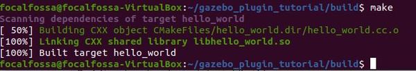
catkin_make
Here is what you should see:

Now let’s run the code. Open up the ROS Master. In a new terminal window, type:
roscore
In another terminal tab, launch the static_turtle_tf2 broadcaster.
rosrun learning_tf2 static_turtle_tf2_broadcaster mystaticturtle 0 0 1 0 0 0
Let’s see if the static_tranform has been published on the tf_static topic.
rostopic echo /tf_static
Here is the output:
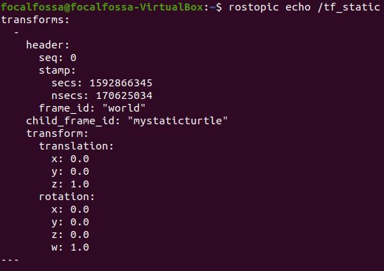
That’s it for static transforms. Note that in practice, you won’t write the code we wrote above. You will instead use the tf2_ros package. The launch file at the bottom of this page is what you would use.
The instructions for writing and using a tf2 static broadcaster in Python are located at this page.
How to Write a tf2 Broadcaster in C++
In this section, we will see how to broadcast coordinate frames of a robot to tf2 using C++. The official tutorial is at this page, but I’ll walk you through the whole process below.
Go to the src folder of the learning_tf2 package.
roscd learning_tf2/src
Open up a new C++ file.
gedit turtle_tf2_broadcaster.cpp
Type the following code:
#include <ros/ros.h>
#include <tf2/LinearMath/Quaternion.h>
#include <tf2_ros/transform_broadcaster.h>
#include <geometry_msgs/TransformStamped.h>
#include <turtlesim/Pose.h>

std::string turtle_name;

void poseCallback(const turtlesim::PoseConstPtr& msg){

  // Create a TransformBroadcaster object that we
  // will use to send the transformations.
  static tf2_ros::TransformBroadcaster br;

  // Create a TransformStamped object which will be the message
  // that will be sent over once it is filled in.
  geometry_msgs::TransformStamped transformStamped;


  // Initialize the TransformedStamped object with some data.
  transformStamped.header.stamp = ros::Time::now(); // Stamp with the current time
  transformStamped.header.frame_id = "world"; // Set name of parent frame of the link
  transformStamped.child_frame_id = turtle_name; // Set the name of the child node of the link

  // Copy information from 3D turtle post to 3D transform
  transformStamped.transform.translation.x = msg->x;
  transformStamped.transform.translation.y = msg->y;
  transformStamped.transform.translation.z = 0.0;
  tf2::Quaternion q;
  q.setRPY(0, 0, msg->theta);
  transformStamped.transform.rotation.x = q.x();
  transformStamped.transform.rotation.y = q.y();
  transformStamped.transform.rotation.z = q.z();
  transformStamped.transform.rotation.w = q.w();

  // Send the transform
  br.sendTransform(transformStamped);
}

int main(int argc, char** argv){
  ros::init(argc, argv, "my_tf2_broadcaster");

  ros::NodeHandle private_node("~");
  if (! private_node.hasParam("turtle"))
  {
    if (argc != 2){ROS_ERROR("need turtle name as argument"); return -1;};
    turtle_name = argv[1];
  }
  else
  {
    private_node.getParam("turtle", turtle_name);
  }

  ros::NodeHandle node;
  ros::Subscriber sub = node.subscribe(turtle_name+"/pose", 10, &poseCallback);

  ros::spin();
  return 0;
};
Click Save and close the editor.
Open up the CMakeLists.txt file.
roscd learning_tf2
gedit CMakeLists.txt
Add the following lines to the bottom of the file:
add_executable(turtle_tf2_broadcaster src/turtle_tf2_broadcaster.cpp)
target_link_libraries(turtle_tf2_broadcaster
 ${catkin_LIBRARIES}
)
Save and close the file.
Now, build the package.
cd ~/catkin_ws/
catkin_make
Now, go back to the package.
roscd learning_tf2
Create a new folder called launch.
mkdir launch
Add the following launch file.
cd launch
gedit start_demo.launch
Type the following code inside it.
 <launch>
     <!-- Turtlesim Node-->
    <node pkg="turtlesim"
	      type="turtlesim_node"
		  name="sim"
    />

    <node pkg="turtlesim"
	      type="turtle_teleop_key"
		  name="teleop"
		  output="screen"
	/>

    <!-- Axes -->
    <param name="scale_linear"
		   value="2"
		   type="double"
	/>
    <param name="scale_angular"
		   value="2"
		   type="double"
	/>
    <node pkg="learning_tf2"
		  type="turtle_tf2_broadcaster"
          args="/turtle1"
		  name="turtle1_tf2_broadcaster"
	/>
    <node pkg="learning_tf2"
		  type="turtle_tf2_broadcaster"
          args="/turtle2"
		  name="turtle2_tf2_broadcaster"
	/>
 </launch>
Click Save and close.
Now edit your CMakeLists.txt file again.
roscd learning_tf2
gedit CMakeLists.txt
Add this at the bottom of the file:
## Mark other files for installation (e.g. launch and bag files, etc.)
install(FILES
 start_demo.launch
 # myfile2
 DESTINATION ${CATKIN_PACKAGE_SHARE_DESTINATION}
)
Save and close the file.
Now type this command:
roslaunch learning_tf2 start_demo.launch
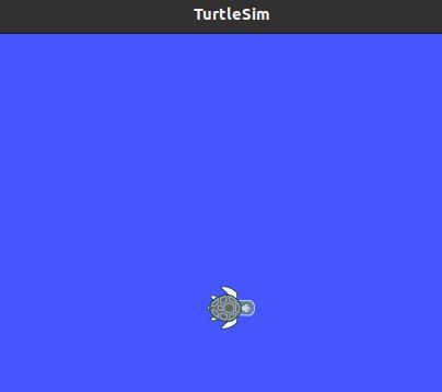
You should see a single turtle.
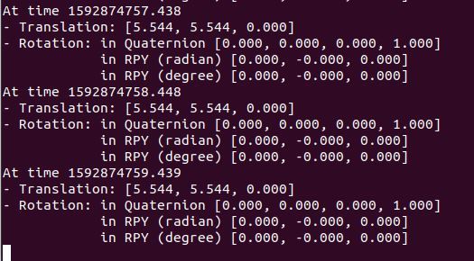
In another terminal window, type this command:
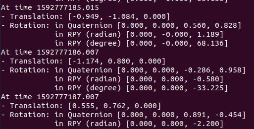
rosrun tf tf_echo /world /turtle1
Select the terminal window where you did the roslaunch command, and drive the turtle around. You should see the pose of turtle1.
Press CTRL+C on all terminal windows to close out everything.
How to Write a tf2 Listener in C++
In this section, we will see how to use tf2 to get access to frame transformations. The official tutorial is at this page, but I’ll walk you through the whole process below.
Go to the src folder of the learning_tf2 package.
roscd learning_tf2/src
Open up a new C++ file.
gedit turtle_tf2_listener.cpp
Type the following code:
#include <ros/ros.h>
#include <tf2_ros/transform_listener.h>
#include <geometry_msgs/TransformStamped.h>
#include <geometry_msgs/Twist.h>
#include <turtlesim/Spawn.h>

int main(int argc, char** argv){
  ros::init(argc, argv, "my_tf2_listener");

  ros::NodeHandle node;

  ros::service::waitForService("spawn");
  ros::ServiceClient spawner =
    node.serviceClient<turtlesim::Spawn>("spawn");
  turtlesim::Spawn turtle;
  turtle.request.x = 4;
  turtle.request.y = 2;
  turtle.request.theta = 0;
  turtle.request.name = "turtle2";
  spawner.call(turtle);

  ros::Publisher turtle_vel =
    node.advertise<geometry_msgs::Twist>("turtle2/cmd_vel", 10);

  // Create TransformListener object to receive tf2 transformations.
  tf2_ros::Buffer tfBuffer;
  tf2_ros::TransformListener tfListener(tfBuffer);

  ros::Rate rate(10.0);


  // Query listener for a specific transformation
  while (node.ok()){
    geometry_msgs::TransformStamped transformStamped;
    try{
	  // Get the transform between two frames
	  // First argument is the target frame, the second argument is the source frame
	  // We want to transform to the target frame from the source frame.
	  // ros::Time(0) gets us the most recent transform.
      transformStamped = tfBuffer.lookupTransform("turtle2", "turtle1",
                               ros::Time(0));
    }
    catch (tf2::TransformException &ex) {
      ROS_WARN("%s",ex.what());
      ros::Duration(1.0).sleep();
      continue;
    }

    geometry_msgs::Twist vel_msg;

    vel_msg.angular.z = 4.0 * atan2(transformStamped.transform.translation.y,
                                    transformStamped.transform.translation.x);
    vel_msg.linear.x = 0.5 * sqrt(pow(transformStamped.transform.translation.x, 2) +
                                  pow(transformStamped.transform.translation.y, 2));
    turtle_vel.publish(vel_msg);

    rate.sleep();
  }
  return 0;
};
Click Save and close the editor.
Open up the CMakeLists.txt file.
roscd learning_tf2
gedit CMakeLists.txt
Add the following lines to the bottom of the file:
add_executable(turtle_tf2_listener src/turtle_tf2_listener.cpp)
target_link_libraries(turtle_tf2_listener
 ${catkin_LIBRARIES}
)
Save and close the file.
Now, build the package.
cd ~/catkin_ws/
catkin_make
Now, go back to the package.
roscd learning_tf2
Go inside the launch file.
cd launch
gedit start_demo.launch
Add the following just before the </launch> tag.
<node pkg="learning_tf2" type="turtle_tf2_listener" name="listener" />
Click Save and close.
Now type this command:
roslaunch learning_tf2 start_demo.launch
You should see two turtles.
Select the terminal window where you did the roslaunch command, and drive the turtle around. You should see one of the turtles follow the other.
Press CTRL+C on all terminal windows to close out everything.
How to Write a tf2 Broadcaster in Python
In this section, we will see how to broadcast coordinate frames of a robot to tf2 using Python. The official tutorial is at this page, but I’ll walk you through the whole process below.
Go to your package, and create a new directory called nodes.
roscd learning_tf2
mkdir nodes
cd nodes
Open a new file called turtle_tf2_broadcaster.py.
gedit turtle_tf2_broadcaster.py
Type the following code inside it.
#!/usr/bin/env python3
import rospy

# Because of transformations
import tf_conversions

import tf2_ros
import geometry_msgs.msg
import turtlesim.msg


def handle_turtle_pose(msg, turtlename):
    br = tf2_ros.TransformBroadcaster()
    t = geometry_msgs.msg.TransformStamped()

    # Give the transform being published a timestamp
    t.header.stamp = rospy.Time.now()

	# Set the name of the parent link
    t.header.frame_id = "world"

	# Set the name of the child node
    t.child_frame_id = turtlename

	# Broadcast the turtle's translation and rotation
	# Published as a transform from frame "world" to frame "turtleX"
	# Copy the information from the 3D turtle post into the
	# 3D transform.
    t.transform.translation.x = msg.x
    t.transform.translation.y = msg.y
    t.transform.translation.z = 0.0
    q = tf_conversions.transformations.quaternion_from_euler(0, 0, msg.theta)
    t.transform.rotation.x = q[0]
    t.transform.rotation.y = q[1]
    t.transform.rotation.z = q[2]
    t.transform.rotation.w = q[3]

    # Pass in the transform and send it
    br.sendTransform(t)

if __name__ == '__main__':
    rospy.init_node('tf2_turtle_broadcaster')

	# This node takes a single parameter "turtle",
	# which specifies a turtle name, e.g. "turtle1" or "turtle2".
    turtlename = rospy.get_param('~turtle')

	# The node subscribes to topic "turtleX/pose"
	# and runs function handle_turtle_pose on every incoming message.
    rospy.Subscriber('/%s/pose' % turtlename,
                     turtlesim.msg.Pose,
                     handle_turtle_pose,
                     turtlename)
    rospy.spin()
Save, and close it.
Make the node executable.
chmod +x nodes/turtle_tf2_broadcaster.py
Now, move into your launch folder.
roscd learning_tf2/launch
Modify your launch file, so that it looks like this.
gedit start_demo.launch
<node name="turtle1_tf2_broadcaster"
      pkg="learning_tf2"
      type="turtle_tf2_broadcaster.py"
      respawn="false"
      output="screen" >
      <param name="turtle" type="string" value="turtle1" />
</node>
<node name="turtle2_tf2_broadcaster"
      pkg="learning_tf2"
      type="turtle_tf2_broadcaster.py"
      respawn="false" output="screen" >
      <param name="turtle" type="string" value="turtle2" />
</node>
Save and close the editor.
Build it.
cd ~/catkin_ws/
catkin_make
Now type:
roslaunch learning_tf2 start_demo.launch
You should see one turtle.
To see the results type this command in another terminal tab:
rosrun tf tf_echo /world /turtle1
If you select the terminal where you typed roslaunch, you will can drive the turtle and watch the pose change.
How to Write a tf2 Listener in Python
In this section, we will see how to use tf2 to get access to frame transformations. The official tutorial is at this page, but I’ll walk you through the whole process below.
Go inside the nodes folder of your package and create a new Python program named turtle_tf2_listener.py.
roscd learning_tf2/nodes
gedit turtle_tf2_listener.py
Type this code in there, and click save.
#!/usr/bin/env python3
import rospy

import math
import tf2_ros
import geometry_msgs.msg
import turtlesim.srv

if __name__ == '__main__':
    rospy.init_node('tf2_turtle_listener')

    tfBuffer = tf2_ros.Buffer()

	# Facilitates the receiving of transforms
    listener = tf2_ros.TransformListener(tfBuffer)

    rospy.wait_for_service('spawn')
    spawner = rospy.ServiceProxy('spawn', turtlesim.srv.Spawn)
    turtle_name = rospy.get_param('turtle', 'turtle2')
    spawner(4, 2, 0, turtle_name)

    turtle_vel = rospy.Publisher('%s/cmd_vel' % turtle_name, geometry_msgs.msg.Twist, queue_size=1)

    rate = rospy.Rate(10.0)
    while not rospy.is_shutdown():
        try:
		    # The arguments are  target frame, source frame. We want to get the latest transform.
            trans = tfBuffer.lookup_transform(turtle_name, 'turtle1', rospy.Time())
        except (tf2_ros.LookupException, tf2_ros.ConnectivityException, tf2_ros.ExtrapolationException):
            rate.sleep()
            continue

        msg = geometry_msgs.msg.Twist()

        msg.angular.z = 4 * math.atan2(trans.transform.translation.y, trans.transform.translation.x)
        msg.linear.x = 0.5 * math.sqrt(trans.transform.translation.x ** 2 + trans.transform.translation.y ** 2)

        turtle_vel.publish(msg)

        rate.sleep()
Close the editor.
Make the node executable.
chmod +x nodes/turtle_tf2_listener.py
Now type:
roscd learning_tf2/launch
gedit start_demo.launch
Add this just before the </launch> tab of the launch file.
<node pkg="learning_tf2" type="turtle_tf2_listener.py" name="listener" output="screen"/>
Save and close the editor.
Build it.
cd ~/catkin_ws/
catkin_make
Now edit your CMakeLists.txt file.
roscd learning_tf2
gedit CMakeLists.txt
Make sure this code is in there somewhere near or at the bottom:
## Mark other files for installation (e.g. launch and bag files, etc.)
install(FILES
 start_demo.launch
 # myfile2
 DESTINATION ${CATKIN_PACKAGE_SHARE_DESTINATION}
)
Save and close.
Now go to a new terminal window, and type this to run the nodes:
roslaunch learning_tf2 start_demo.launch
You’re done! Keep building!