In this tutorial, we will demonstrate how to remap a topic called /chatter from the command line using ROS 2.
Remapping topics can be useful in several scenarios, such as avoiding naming conflicts when multiple nodes publish or subscribe to topics with the same name, or integrating third-party packages that use different topic names than your existing system.
We will use the built-in demo_nodes_cpp package, which contains a simple publisher (talker) and subscriber (listener) pair.
The talker node publishes messages on the /chatter topic, and the listener node subscribes to the /chatter topic.
Prerequisites
You have ROS 2 installed.
Command Line
First, open a new terminal and source your ROS 2 installation.
Run the talker node without remapping:
ros2 run demo_nodes_cpp talker
Open another terminal, and run the listener node without remapping:
ros2 run demo_nodes_cpp listener
You should see the listener node receiving messages from the talker node on the /chatter topic.
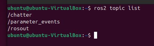
In a new terminal, run ros2 topic list to see the available topics:
ros2 topic list
You should see the /chatter topic in the list.
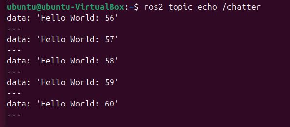
To verify that the talker node is publishing messages on the /chatter topic, run ros2 topic echo:
ros2 topic echo /chatter
You should see the messages being published by the talker node.
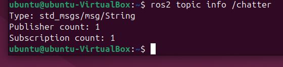
Run ros2 topic info to see the total number of publishers and subscribers for the /chatter topic:
ros2 topic info /chatter
You should see that there is one publisher and one subscriber for the /chatter topic.
Now, let’s remap the talker node to publish on a new topic called /conversation.
Stop the talker node using CTRL + C, and type this:
ros2 run demo_nodes_cpp talker --ros-args -r /chatter:=/conversation
Check the listener node terminal. You will notice that it is no longer receiving messages because it is still subscribed to the /chatter topic.
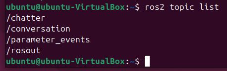
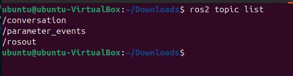
Run ros2 topic list again:
ros2 topic list
You will see the new /conversation topic in the list, but the /chatter topic is no longer present.
If you run ros2 topic echo /conversation, you will see the messages being published by the talker node on the new topic:
ros2 topic echo /conversation
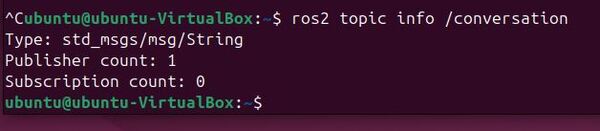
Run ros2 topic info for the /conversation topic:
ros2 topic info /conversation
You should see that there is one publisher and no subscribers for the /conversation topic.
To make the listener node receive messages from the talker node again, we need to remap its subscription from /chatter to /conversation. Stop the listener node (Ctrl+C) and run it with the remapping argument:
ros2 run demo_nodes_cpp listener --ros-args -r /chatter:=/conversation
Now, the listener node will receive messages from the talker node on the remapped /conversation topic.
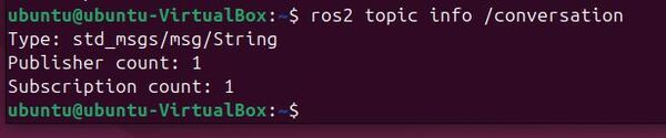
Run ros2 topic info for the /conversation topic again:
ros2 topic info /conversation
You should now see that there is one publisher and one subscriber for the /conversation topic.
In a Launch File
To remap topics using a launch file in ROS 2, you can use the <remap> tag within the <node> tag.
Create a new launch file called remap_demo.launch.py:
#!/usr/bin/env python3
"""
ROS 2 Topic Remapping Launch File.

This launch file demonstrates how to remap topics in ROS 2 by launching a talker and listener
node pair with remapped topic names. It shows how to change the default topic '/chatter'
to '/conversation' for both nodes.

Launch File Nodes:
    * talker_node (demo_nodes_cpp/talker): Publishes messages on remapped topic
    * listener_node (demo_nodes_cpp/listener): Subscribes to messages on remapped topic

Topic Remappings:
    * /chatter -> /conversation: Remaps the default topic to a new name for both nodes

Example Usage:
    $ ros2 launch your_package remap_demo.launch.py

:author: Addison Sears-Collins
:date: November 26, 2024
"""

# Import the necessary ROS 2 launch modules
from launch import LaunchDescription
from launch_ros.actions import Node


def generate_launch_description():
    """
    Generate a launch description for topic remapping demonstration.

    This function creates and returns a LaunchDescription object that specifies how
    to launch and configure the talker and listener nodes with topic remapping.

    Returns
    -------
    LaunchDescription
        A launch description object containing the configured nodes
    """
    return LaunchDescription([
        # Create and configure the talker node
        # This node will publish messages on the remapped topic '/conversation'
        Node(
            package='demo_nodes_cpp',      # The package containing the node
            executable='talker',           # The name of the executable
            name='talker_node',           # A unique name for this node instance
            remappings=[
                # Remap the default '/chatter' topic to '/conversation'
                ('/chatter', '/conversation'),
            ],
            output='screen'               # Display node output in the terminal
        ),

        # Create and configure the listener node
        # This node will subscribe to messages on the remapped topic '/conversation'
        Node(
            package='demo_nodes_cpp',      # The package containing the node
            executable='listener',         # The name of the executable
            name='listener_node',         # A unique name for this node instance
            remappings=[
                # Remap the default '/chatter' topic to '/conversation'
                # This must match the talker's remapping to receive messages
                ('/chatter', '/conversation'),
            ],
            output='screen'               # Display node output in the terminal
        ),
    ])
In this launch file, we define two nodes: talker and listener. For each node, we specify the package, executable, and name. We also use the remappings parameter to remap the /chatter topic to /conversation for both nodes.
To run the launch file, open a new terminal, source your ROS 2 installation, and navigate to the package containing the remap_demo.launch.py file. Then, run the following command:
ros2 launch remap_demo.launch.py
You should see both the talker and listener nodes running, with the talker node publishing messages on the /conversation topic and the listener node subscribing to the /conversation topic.
In a new terminal, run ros2 topic list to see the available topics:
ros2 topic list
You should see the /conversation topic in the list.
To verify that the talker node is publishing messages on the /conversation topic, run ros2 topic echo:
ros2 topic echo /conversation
You should see the messages being published by the talker node.
Run ros2 topic info for the /conversation topic:
ros2 topic info /conversation
You should see that there is one publisher and one subscriber for the /conversation topic.
Using a launch file to remap topics has several advantages:
It allows you to centralize the configuration of your nodes and their remappings in a single file.
It makes it easier to manage complex systems with multiple nodes and remappings.
It enables you to create reusable launch files that can be shared across different projects or with other users.
In this tutorial, we will learn how to run ROS 2 on different machines using the ROS_DOMAIN_ID environment variable.
We will use the built-in demo_nodes_cpp package as an example, running the talker node on one machine to broadcast “Hello World” messages over a topic called /chatter. We will run the listener node on another machine.
Prerequisites
You have ROS 2 installed on multiple computers.
Directions
First, ensure both computers are on the same network.
Connect both machines to the same WiFi network or connect them using an Ethernet cable.
We will now set the ROS_DOMAIN_ID on the first machine.
The ROS_DOMAIN_ID is like a unique channel number that allows ROS 2 nodes to communicate with each other when they are set to the same value, preventing interference from other ROS 2 systems on the same network. The default ROS_DOMAIN_ID is 0, and safe values range from 0 to 101, inclusive.
Open a terminal on the first machine.
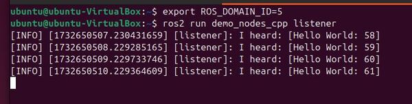
Set the ROS_DOMAIN_ID to a valid integer value, e.g., 5:
export ROS_DOMAIN_ID=5
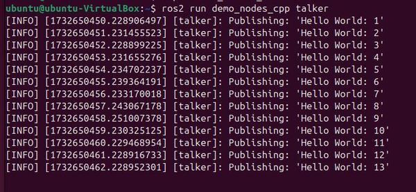
Run the talker node:
ros2 run demo_nodes_cpp talker
Set the ROS_DOMAIN_ID on the second machine (listener).
Open a terminal on the second machine.
Set the ROS_DOMAIN_ID to the same value as the first machine:
export ROS_DOMAIN_ID=5
Run the listener node:
ros2 run demo_nodes_cpp listener
Observe the communication. The listener node on the second machine should receive messages from the talker node on the first machine.
Press CTRL + C on the second machine (the one with the listener node).
Experiment with different ROS_DOMAIN_ID values.
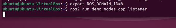
Set a different ROS_DOMAIN_ID on the second machine, e.g., 8:
export ROS_DOMAIN_ID=8
Run the listener node again:
ros2 run demo_nodes_cpp listener
Observe that the listener node no longer receives messages from the talker node because they are on different ROS domains.
Make the ROS_DOMAIN_ID change permanent
Open the .bashrc file in a text editor:
gedit ~/.bashrc
Add the following line at the end of the file:
export ROS_DOMAIN_ID=5
Save the file and exit the text editor.
Source the .bashrc file or open a new terminal for the changes to take effect:
source ~/.bashrc
You can now rerun the listener.
ros2 run demo_nodes_cpp listener
Everything is working again.
By following these steps, you can run ROS 2 nodes on different machines using the ROS_DOMAIN_ID environment variable to ensure they communicate on the same ROS domain.
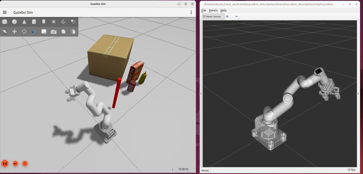
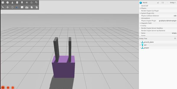
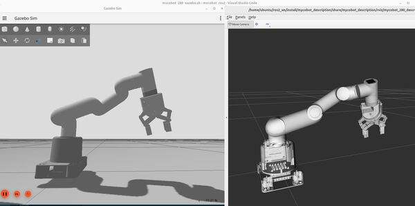
In this tutorial, we will simulate and control a robotic arm in Gazebo. I will show you how to set up and control a robotic arm using ROS 2 Control and Gazebo.
By the end of this tutorial, you will be able to build this:
If you prefer to learn by video instead of text, you can follow the complete tutorial here:
What is Gazebo?
Ever wondered how robotics engineers test their robots without risking expensive hardware?
Enter Gazebo – a simulator that lets you test robots in a virtual world before building them in real life. You can work with different types of robots and connect them with ROS 2, which means your virtual tests will translate to real robots. This makes Gazebo an important tool when you’re developing and perfecting robotics projects.
What is ROS 2 Control?
Imagine you want to control a robot – maybe move its arm or make its wheels turn. You need a way for your computer programs to talk to the robot’s physical parts (like motors and sensors). This is where ROS 2 Control comes in.
ROS 2 Control is like a universal translator between:
Your control programs (the software you write)
The robot’s physical parts (the hardware)
How It Works
Where it runs:
ROS 2 Control lives on the main computer that controls your robot
This could be a laptop, Raspberry Pi, Intel NUC, or any computer running ROS 2
Sending Commands (Software → Hardware)
You write a program to make the robot move
ROS 2 Control takes these commands
It translates them into instructions the robot’s hardware can understand
These instructions go to devices like Arduino boards that directly control the motors
Getting Feedback (Hardware → Software)
The robot’s sensors and motors send back information
For example: “Motor #1 is currently at 45 degrees”
ROS 2 Control receives this information
It shares this data with other ROS 2 programs that need it
Real-World Example: Moving a Robotic Arm
Let’s look at how ROS 2 Control works with a robotic arm that has 6 degrees of freedom (like the myCobot robotic arms) – meaning it can move in 6 different ways, just like your human arm. Each degree comes from a motor, or “joint,” that enables specific movements. Want to pick up a cup? Here’s how ROS 2 Control makes this happen:
Your Program’s Command
You want the arm to move to pick up the cup.
Your program (i.e. MoveIt 2) calculates all the positions each joint needs to move through to get the gripper from the starting location to the goal location around the cup.
Your program sends a “joint trajectory” – think of it as a list of positions for each joint- to the Joint Trajectory Controller (which is part of ROS 2 Control)
For example: “Joint 1 should move from 0° to 45°, Joint 2 from 30° to 60°, etc…”
ROS 2 Control’s Job
The Joint Trajectory Controller gets this list of joint positions
The Joint Trajectory Controller knows it needs to smoothly move through these positions and passes the appropriate angle values to the Hardware Interface.
The Hardware Interface sends these commands to the microcontroller many times per second
Arduino’s Role
Gets these commands through a USB cable
Controls the actual motors in the robot arm
Tells each motor exactly how fast and how far to turn
Also reads sensors (called encoders) on each motor
Feedback Path (This is important!)
Arduino constantly reads the sensors: “Joint 1 is at 22°, Joint 2 is at 45°…”
Sends this information back to ROS 2 Control
ROS 2 Control shares this with your program
Your program can check if the arm is moving correctly
Continuous Process
This whole cycle happens many times every second
Your program keeps checking the arm’s position
ROS 2 Control keeps sending updated commands
Arduino keeps moving motors and reading sensors
Until the arm reaches all the positions needed to pick up the cup
What ROS 2 Control Does For You
ROS 2 Control provides a standard hardware interface – think of it like a universal adapter between your software and robot hardware. With ROS 2 Control:
You only need to think about where you want the arm to move
Don’t need to worry about how to control individual motors
Can focus on the task (picking up the cup) instead of the details
Works with different types of robot arms – just change the settings
Write your robot program once
Want to switch from servo motors to stepper motors? Just update a configuration file
Your original program keeps working without changes
Can more easily share your code with others
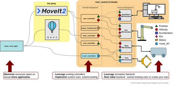
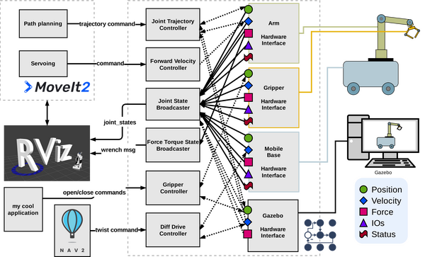
A complete block diagram showing an overview of ROS 2 Control is on this page.
Real Hardware + ROS 2 Control: Following a Single Command
Let’s take a look at a more technical example of how ROS 2 Control works for a real robotics project. We will follow a joint position command as it travels through each part of ROS 2 Control, looking at exactly at the inputs and outputs at each stage. Think of it like tracking a package through the delivery system.
1. The Starting Point: Terminal Command or MoveIt 2 Action
e.g. “p <joint1_pos> <joint2_pos> <joint3_pos> …\r”
“p 1500 1200 1800 … \r”
Here, each value represents the target position of a servo in microseconds, corresponding to each joint in the arm.
4. Arduino (The Final Handler)
INPUT: The serial message from the ROS 2 Control hardware interface
OUTPUT: Motor commands
Servo1: 50.0 degrees
Servo2: 20.0 degrees
(and so on for each servo)
Gazebo + ROS 2 Control: Following a Single Command
Now that we have taken a look at what happens in a real robotics project, let’s understand how Gazebo and ROS 2 Control interact with each other by tracking the same joint command.
1. The Starting Point: Terminal Command or MoveIt 2 Action
OUTPUT: Gazebo physics commands (internal to Gazebo)
SetPosition(“link1_to_link2”, 0.5)
SetPosition(“link2_to_link3”, 0.2)
(and so on for each joint)
4. Gazebo Physics Engine (The Virtual Robot)
INPUT: Physics commands for each joint
Position setpoints in radians
OUTPUT: Simulated motion
Updates joint positions in physics simulation
Considers inertia, gravity, joint limits
Provides visual feedback in Gazebo
Key Similarities Between Gazebo and Real Hardware
Control Flow: Both use the same ROS 2 Control architecture and message pipeline
Joint Interfaces: Same position/velocity/effort command and state interfaces are used
Update Rate: Both typically run control loops at similar frequencies (e.g., 50Hz, 100Hz)
Command Format: Joint commands from the software (e.g. MoveIt 2) use identical message types and coordinate systems
Key Differences Between Gazebo and Real Hardware
Communication Layer: Real hardware requires serial protocols and motor drivers, while Gazebo interfaces directly through its simulation system
Motion Physics: Real robots must handle physical wear, friction and imperfections. Gazebo uses idealized physics models
System Feedback: Real hardware relies on potentially noisy sensor data, while Gazebo provides perfect state information from its physics engine
Error Handling: Real systems need robust error detection and recovery. Gazebo simulation can ignore many real-world failure modes
The beauty of simulation is that the commands flow through almost the same path, but instead of dealing with real motors and encoders, everything happens in the physics engine. This makes testing and development safer and faster.
Each stage transforms the command into something the next stage can understand, like a series of translators working together to deliver your message to the robot.
Let’s put this knowledge into practice by setting up our own robot simulation. We’ll start by creating the necessary ROS 2 packages that will house our configuration files, launch scripts, and test code.
Create Packages
Navigate to your workspace and create the following packages. You can replace the maintainer-name and maintainer email with your own information.
Now add one more world. We will call it: pick_and_place_demo.world.
gedit pick_and_place_demo.world
<?xml version="1.0" ?>

<sdf version="1.7">
  <world name="default">

    <!-- Plugin for simulating physics -->
    <plugin
      filename="gz-sim-physics-system"
      name="gz::sim::systems::Physics">
      <engine>
        <filename>libgz-physics-bullet-featherstone-plugin.so</filename>
      </engine>
    </plugin>

    <!-- Plugin for handling user commands -->
    <plugin
      filename="gz-sim-user-commands-system"
      name="gz::sim::systems::UserCommands">
    </plugin>

    <!-- Plugin for broadcasting scene updates -->
    <plugin
      filename="gz-sim-scene-broadcaster-system"
      name="gz::sim::systems::SceneBroadcaster">
    </plugin>

    <!-- Plugin for sensor handling -->
    <plugin
      filename="gz-sim-sensors-system"
      name="gz::sim::systems::Sensors">
      <render_engine>ogre2</render_engine>
    </plugin>

    <!-- Plugin for IMU -->
    <plugin filename="gz-sim-imu-system"
      name="gz::sim::systems::Imu">
    </plugin>

    <!-- To add realistic gravity, do: 0.0 0.0 -9.8, otherwise do 0.0 0.0 0.0 -->
    <gravity>0.0 0.0 -9.8</gravity>

    <!-- Include a model of the Sun from an external URI -->
    <include>
      <uri>
        https://fuel.gazebosim.org/1.0/OpenRobotics/models/Sun
      </uri>
    </include>

    <!-- Local Ground Plane with modified friction -->
    <model name="ground_plane">
      <static>true</static>
      <link name="link">
        <collision name="collision">
          <geometry>
            <plane>
              <normal>0 0 1</normal>
            </plane>
          </geometry>
          <surface>
            <friction>
              <torsional>
                <coefficient>0.0</coefficient>
              </torsional>
            </friction>
          </surface>
        </collision>
        <visual name="visual">
          <geometry>
            <plane>
              <normal>0 0 1</normal>
              <size>100 100</size>
            </plane>
          </geometry>
          <material>
            <ambient>0.8 0.8 0.8 1</ambient>
            <diffuse>0.8 0.8 0.8 1</diffuse>
            <specular>0.8 0.8 0.8 1</specular>
          </material>
        </visual>
      </link>
    </model>

    <!-- Include the cylinder model -->
    <include>
      <uri>model://red_cylinder</uri>
      <name>red_cylinder</name>
      <pose>0.22 0.12 0.175 0 0 0</pose>
    </include>

    <!-- Include the other objects -->

    <include>
      <uri>model://mustard</uri>
      <pose>0.7 0.15 0.08 0 0 0</pose>
    </include>

    <include>
      <uri>model://cheezit_big_original</uri>
      <pose>0.64 0.23 0.13 1.571 0 0</pose>
    </include>

    <include>
      <uri>model://cardboard_box</uri>
      <pose>0.65 0.60 0.15 0 0 0.5</pose>
    </include>

    <include>
      <uri>model://coke_can</uri>
      <pose>0.5 0.15 0.0 0 0 2.3</pose>
    </include>

    <!-- Define scene properties -->
    <scene>
      <shadows>false</shadows>
    </scene>

  </world>
</sdf>
Now we need to add models to our models folder. Models are physical objects that will exist inside your house and pick_and_place_demo worlds. These objects include things like boxes, lamps, chairs, and tables.
Let’s walk through one of those models. We will take a look at the refrigerator model.
The refrigerator model is defined using the Simulation Description Format (SDF) version 1.6. Here’s a breakdown of its structure:
The model is named “aws_robomaker_residential_Refrigerator_01“. It contains a single link, which represents the main body of the refrigerator.
The link has three main components:
Inertial properties: A mass of 1 unit is specified, which affects how the object behaves in physical simulations.
Collision geometry: This defines the shape used for collision detection. It uses a mesh file named “aws_Refrigerator_01_collision.DAE” located in the model’s meshes directory. This mesh is a simplified version of the refrigerator’s shape for efficient collision calculations.
Visual geometry: This defines how the refrigerator looks in the simulation. It uses a separate mesh file named “aws_Refrigerator_01_visual.DAE“. This mesh is more detailed than the collision mesh to provide a realistic appearance.
Both the collision and visual meshes are scaled to 1:1:1, meaning they use their original size.
The visual component also includes a metadata tag specifying it belongs to layer 1, which is used for rendering or interaction purposes in the simulation environment.
Finally, the model is set to static, meaning it won’t move during the simulation. This is appropriate for a large appliance like a refrigerator that typically stays in one place.
This structure allows the simulation to efficiently handle both the physical interactions and visual representation of the refrigerator in the Gazebo virtual environment.
Oh and one other thing I should mention. DAE (Digital Asset Exchange) files, also known as COLLADA (COLLAborative Design Activity) files, can be created by various 3D modeling and animation software.
The DAE format is widely used in game development, virtual reality, augmented reality, and simulation environments because it’s an open standard that can store 3D assets along with their associated metadata.
For the specific refrigerator model mentioned in the SDF file, it was likely created using a 3D modeling software as part of the AWS RoboMaker residential models set. The modelers would have created both a detailed visual mesh and a simplified collision mesh, exporting each as separate DAE files for use in the simulation environment.
The model.sdf and model.config files are typically created manually using a basic text editor.
To see your house.world file in action, move to the worlds folder in the terminal.
cd ~/ros2_ws/src/mycobot_ros2/mycobot_gazebo/worlds/
Type the following command to let Gazebo know how to find the models:
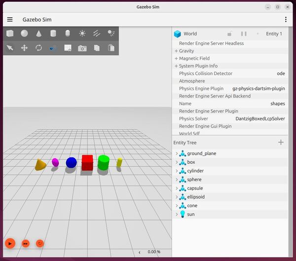
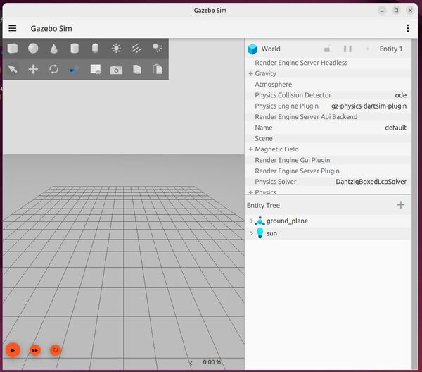
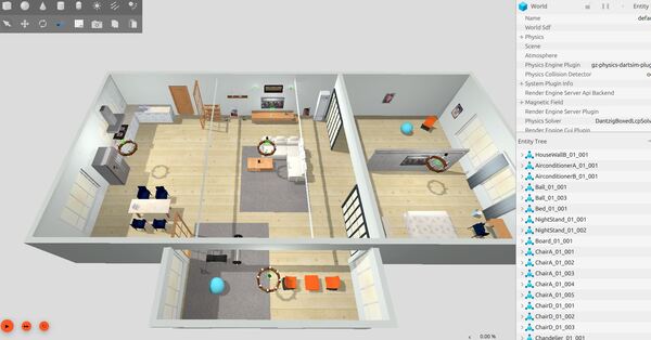
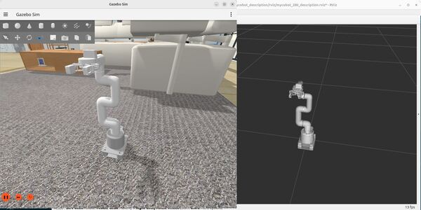
Now launch your Gazebo world. Be patient. It takes a while to load. If prompted, click “Wait”. Do not click “Force Quit.”
gz sim house.world
Now type:
gz sim pick_and_place_demo.world
Press CTRL + C to close.
Connect Gazebo to ROS 2 Control
Create a YAML Configuration File for the Controller Manager
After setting up our simulation environment in Gazebo, we need to tell ROS 2 Control how to manage our robot’s movements in this virtual world. Let’s create a configuration file that defines how our robot’s joints should be controlled.
The configuration file acts as a bridge between Gazebo and ROS 2, defining:
How often the controllers should update (100Hz)
Which joints can move
How these joints should move (position, velocity, etc.)
What kind of feedback the system should provide
Think of this file as a manual that tells Gazebo:
What parts of your robot can move
How they’re allowed to move
How to report back the robot’s current state
This configuration is essential because it ensures your simulated robot behaves similarly to how a real robot would respond to commands.
Open a terminal window, and type:
cd ~/ros2_ws/src/mycobot_ros2/mycobot_moveit_config/
mkdir -p config/mycobot_280
Create a new file inside the config/mycobot_280 directory called:
ros2_controllers.yaml
Add this code:
# controller_manager provides the necessary infrastructure to manage multiple controllers
# efficiently and robustly using ROS 2 Control.
controller_manager:
  ros__parameters:
    update_rate: 100 # update_rate specifies how often (in Hz) the controllers should be updated.

    # The JointTrajectoryController allows you to send joint trajectory commands to a group
    # of joints on a robot. These commands specify the desired positions for each joint.
    arm_controller:
      type: joint_trajectory_controller/JointTrajectoryController

    # Controls the gripper
    gripper_action_controller:
      type: position_controllers/GripperActionController

    # Responsible for publishing the current state of the robot's
    # joints to the /joint_states ROS 2 topic
    joint_state_broadcaster:
      type: joint_state_broadcaster/JointStateBroadcaster

# Define the parameters for each controller
arm_controller:
  ros__parameters:
    joints:
      - link1_to_link2
      - link2_to_link3
      - link3_to_link4
      - link4_to_link5
      - link5_to_link6
      - link6_to_link6_flange

    # The controller will expect position commands as input for each of these joints.
    command_interfaces:
      - position

    # Tells the controller that it should expect to receive position data as the state
    # feedback from the hardware interface.
    state_interfaces:
      - position

    # If true, When set to true, the controller will not use any feedback from the system
    # (e.g., joint positions, velocities, efforts) to compute the control commands.
    open_loop_control: false

    # When set to true, it allows the controller to integrate the trajectory goals it receives.
    # This means that if the goal trajectory only specifies positions, the controller will
    # numerically integrate the positions to compute the velocities and accelerations required
    # to follow the trajectory.
    allow_integration_in_goal_trajectories: true

    # Allow non-zero velocity at the end of the trajectory
    allow_nonzero_velocity_at_trajectory_end: true

gripper_action_controller:
  ros__parameters:
    joint: gripper_controller
    action_monitor_rate: 20.0
    goal_tolerance: 0.01
    max_effort: 100.0
    allow_stalling: false
    stall_velocity_threshold: 0.001
    stall_timeout: 1.0
Save the file, and close it.
Create a new file inside the config/mycobot_280 directory called:
ros2_controllers_template.yaml
# controller_manager provides the necessary infrastructure to manage multiple controllers
# efficiently and robustly using ROS 2 Control.
controller_manager:
  ros__parameters:
    update_rate: 100 # update_rate specifies how often (in Hz) the controllers should be updated.

    # The JointTrajectoryController allows you to send joint trajectory commands to a group
    # of joints on a robot. These commands specify the desired positions for each joint.
    arm_controller:
      type: joint_trajectory_controller/JointTrajectoryController

    # Controls the gripper
    gripper_action_controller:
      type: position_controllers/GripperActionController

    # Responsible for publishing the current state of the robot's
    # joints to the /joint_states ROS 2 topic
    joint_state_broadcaster:
      type: joint_state_broadcaster/JointStateBroadcaster

# Define the parameters for each controller
arm_controller:
  ros__parameters:
    joints:
      - ${prefix}link1_to_${prefix}link2
      - ${prefix}link2_to_${prefix}link3
      - ${prefix}link3_to_${prefix}link4
      - ${prefix}link4_to_${prefix}link5
      - ${prefix}link5_to_${prefix}link6
      - ${prefix}link6_to_${prefix}${flange_link}

    # The controller will expect position commands as input for each of these joints.
    command_interfaces:
      - position

    # Tells the controller that it should expect to receive position data as the state
    # feedback from the hardware interface.
    state_interfaces:
      - position

    # If true, When set to true, the controller will not use any feedback from the system
    # (e.g., joint positions, velocities, efforts) to compute the control commands.
    open_loop_control: false

    # When set to true, it allows the controller to integrate the trajectory goals it receives.
    # This means that if the goal trajectory only specifies positions, the controller will
    # numerically integrate the positions to compute the velocities and accelerations required
    # to follow the trajectory.
    allow_integration_in_goal_trajectories: true

    # Allow non-zero velocity at the end of the trajectory
    allow_nonzero_velocity_at_trajectory_end: true

gripper_action_controller:
  ros__parameters:
    joint: ${prefix}gripper_controller
    action_monitor_rate: 20.0
    goal_tolerance: 0.01
    max_effort: 100.0
    allow_stalling: false
    stall_velocity_threshold: 0.001
    stall_timeout: 1.0
This file will help us substitute a prefix (e.g. “left” or “right”) should we desire, for example.
Update CMakeLists.txt with the new config folder. Here is CMakeLists.txt for the mycobot_moveit_config package.
cmake_minimum_required(VERSION 3.8)
project(mycobot_moveit_config)

if(CMAKE_COMPILER_IS_GNUCXX OR CMAKE_CXX_COMPILER_ID MATCHES "Clang")
  add_compile_options(-Wall -Wextra -Wpedantic)
endif()

# find dependencies
find_package(ament_cmake REQUIRED)
# uncomment the following section in order to fill in
# further dependencies manually.
# find_package(<dependency> REQUIRED)

# Copy necessary files to designated locations in the project
install (
  DIRECTORY config launch
  DESTINATION share/${PROJECT_NAME}
)

if(BUILD_TESTING)
  find_package(ament_lint_auto REQUIRED)
  # the following line skips the linter which checks for copyrights
  # comment the line when a copyright and license is added to all source files
  set(ament_cmake_copyright_FOUND TRUE)
  # the following line skips cpplint (only works in a git repo)
  # comment the line when this package is in a git repo and when
  # a copyright and license is added to all source files
  set(ament_cmake_cpplint_FOUND TRUE)
  ament_lint_auto_find_test_dependencies()
endif()

ament_package()
#!/usr/bin/env python3
"""
Launch RViz visualization for the mycobot robot.

This launch file sets up the complete visualization environment for the mycobot robot,
including robot state publisher, joint state publisher, and RViz2. It handles loading
and processing of URDF/XACRO files and controller configurations.

:author: Addison Sears-Collins
:date: November 15, 2024
"""
import os
from pathlib import Path
from launch import LaunchDescription
from launch.actions import DeclareLaunchArgument, OpaqueFunction
from launch.conditions import IfCondition, UnlessCondition
from launch.substitutions import Command, LaunchConfiguration, PathJoinSubstitution
from launch_ros.actions import Node
from launch_ros.parameter_descriptions import ParameterValue
from launch_ros.substitutions import FindPackageShare


def process_ros2_controllers_config(context):
    """Process the ROS 2 controller configuration yaml file before loading the URDF.

    This function reads a template configuration file, replaces placeholder values
    with actual configuration, and writes the processed file to both source and
    install directories.

    Args:
        context: Launch context containing configuration values

    Returns:
        list: Empty list as required by OpaqueFunction
    """

    # Get the configuration values
    prefix = LaunchConfiguration('prefix').perform(context)
    flange_link = LaunchConfiguration('flange_link').perform(context)
    robot_name = LaunchConfiguration('robot_name').perform(context)

    home = str(Path.home())

    # Define both source and install paths
    src_config_path = os.path.join(
        home,
        'ros2_ws/src/mycobot_ros2/mycobot_moveit_config/config',
        robot_name
    )
    install_config_path = os.path.join(
        home,
        'ros2_ws/install/mycobot_moveit_config/share/mycobot_moveit_config/config',
        robot_name
    )

    # Read from source template
    template_path = os.path.join(src_config_path, 'ros2_controllers_template.yaml')
    with open(template_path, 'r', encoding='utf-8') as file:
        template_content = file.read()

    # Create processed content (leaving template untouched)
    processed_content = template_content.replace('${prefix}', prefix)
    processed_content = processed_content.replace('${flange_link}', flange_link)

    # Write processed content to both source and install directories
    for config_path in [src_config_path, install_config_path]:
        os.makedirs(config_path, exist_ok=True)
        output_path = os.path.join(config_path, 'ros2_controllers.yaml')
        with open(output_path, 'w', encoding='utf-8') as file:
            file.write(processed_content)

    return []


# Define the arguments for the XACRO file
ARGUMENTS = [
    DeclareLaunchArgument('robot_name', default_value='mycobot_280',
                          description='Name of the robot'),
    DeclareLaunchArgument('prefix', default_value='',
                          description='Prefix for robot joints and links'),
    DeclareLaunchArgument('add_world', default_value='true',
                          choices=['true', 'false'],
                          description='Whether to add world link'),
    DeclareLaunchArgument('base_link', default_value='base_link',
                          description='Name of the base link'),
    DeclareLaunchArgument('base_type', default_value='g_shape',
                          description='Type of the base'),
    DeclareLaunchArgument('flange_link', default_value='link6_flange',
                          description='Name of the flange link'),
    DeclareLaunchArgument('gripper_type', default_value='adaptive_gripper',
                          description='Type of the gripper'),
    DeclareLaunchArgument('use_gazebo', default_value='false',
                          choices=['true', 'false'],
                          description='Whether to use Gazebo simulation'),
    DeclareLaunchArgument('use_gripper', default_value='true',
                          choices=['true', 'false'],
                          description='Whether to attach a gripper')
]


def generate_launch_description():
    """Generate the launch description for the mycobot robot visualization.

    This function sets up all necessary nodes and parameters for visualizing
    the mycobot robot in RViz, including:
    - Robot state publisher for broadcasting transforms
    - Joint state publisher for simulating joint movements
    - RViz for visualization

    Returns:
        LaunchDescription: Complete launch description for the visualization setup
    """
    # Define filenames
    urdf_package = 'mycobot_description'
    urdf_filename = 'mycobot_280.urdf.xacro'
    rviz_config_filename = 'mycobot_280_description.rviz'

    # Set paths to important files
    pkg_share_description = FindPackageShare(urdf_package)
    default_urdf_model_path = PathJoinSubstitution(
        [pkg_share_description, 'urdf', 'robots', urdf_filename])
    default_rviz_config_path = PathJoinSubstitution(
        [pkg_share_description, 'rviz', rviz_config_filename])

    # Launch configuration variables
    jsp_gui = LaunchConfiguration('jsp_gui')
    rviz_config_file = LaunchConfiguration('rviz_config_file')
    urdf_model = LaunchConfiguration('urdf_model')
    use_rviz = LaunchConfiguration('use_rviz')
    use_sim_time = LaunchConfiguration('use_sim_time')

    # Declare the launch arguments
    declare_jsp_gui_cmd = DeclareLaunchArgument(
        name='jsp_gui',
        default_value='true',
        choices=['true', 'false'],
        description='Flag to enable joint_state_publisher_gui')

    declare_rviz_config_file_cmd = DeclareLaunchArgument(
        name='rviz_config_file',
        default_value=default_rviz_config_path,
        description='Full path to the RVIZ config file to use')

    declare_urdf_model_path_cmd = DeclareLaunchArgument(
        name='urdf_model',
        default_value=default_urdf_model_path,
        description='Absolute path to robot urdf file')

    declare_use_rviz_cmd = DeclareLaunchArgument(
        name='use_rviz',
        default_value='true',
        description='Whether to start RVIZ')

    declare_use_sim_time_cmd = DeclareLaunchArgument(
        name='use_sim_time',
        default_value='false',
        description='Use simulation (Gazebo) clock if true')

    robot_description_content = ParameterValue(Command([
        'xacro', ' ', urdf_model, ' ',
        'robot_name:=', LaunchConfiguration('robot_name'), ' ',
        'prefix:=', LaunchConfiguration('prefix'), ' ',
        'add_world:=', LaunchConfiguration('add_world'), ' ',
        'base_link:=', LaunchConfiguration('base_link'), ' ',
        'base_type:=', LaunchConfiguration('base_type'), ' ',
        'flange_link:=', LaunchConfiguration('flange_link'), ' ',
        'gripper_type:=', LaunchConfiguration('gripper_type'), ' ',
        'use_gazebo:=', LaunchConfiguration('use_gazebo'), ' ',
        'use_gripper:=', LaunchConfiguration('use_gripper')
    ]), value_type=str)

    # Subscribe to the joint states of the robot, and publish the 3D pose of each link.
    start_robot_state_publisher_cmd = Node(
        package='robot_state_publisher',
        executable='robot_state_publisher',
        name='robot_state_publisher',
        output='screen',
        parameters=[{
            'use_sim_time': use_sim_time,
            'robot_description': robot_description_content}])

    # Publish the joint state values for the non-fixed joints in the URDF file.
    start_joint_state_publisher_cmd = Node(
        package='joint_state_publisher',
        executable='joint_state_publisher',
        name='joint_state_publisher',
        parameters=[{'use_sim_time': use_sim_time}],
        condition=UnlessCondition(jsp_gui))

    # Depending on gui parameter, either launch joint_state_publisher or joint_state_publisher_gui
    start_joint_state_publisher_gui_cmd = Node(
        package='joint_state_publisher_gui',
        executable='joint_state_publisher_gui',
        name='joint_state_publisher_gui',
        parameters=[{'use_sim_time': use_sim_time}],
        condition=IfCondition(jsp_gui))

    # Launch RViz
    start_rviz_cmd = Node(
        condition=IfCondition(use_rviz),
        package='rviz2',
        executable='rviz2',
        name='rviz2',
        output='screen',
        arguments=['-d', rviz_config_file],
        parameters=[{'use_sim_time': use_sim_time}])

    # Create the launch description and populate
    ld = LaunchDescription(ARGUMENTS)

    # Process the controller configuration before starting nodes
    ld.add_action(OpaqueFunction(function=process_ros2_controllers_config))

    # Declare the launch options
    ld.add_action(declare_jsp_gui_cmd)
    ld.add_action(declare_rviz_config_file_cmd)
    ld.add_action(declare_urdf_model_path_cmd)
    ld.add_action(declare_use_rviz_cmd)
    ld.add_action(declare_use_sim_time_cmd)

    # Add any actions
    ld.add_action(start_joint_state_publisher_cmd)
    ld.add_action(start_joint_state_publisher_gui_cmd)
    ld.add_action(start_robot_state_publisher_cmd)
    ld.add_action(start_rviz_cmd)

    return ld
Let’s discuss the key components of the configuration files.
Controller Manager
The controller manager acts as the central orchestrator, running at 100Hz to manage multiple controllers simultaneously. This high update rate ensures smooth motion control and responsive behavior of the robot.
Arm Controller (JointTrajectoryController)
This controller handles the coordinated motion of the robot’s six-axis arm. It uses a joint trajectory controller implementation, which means it can process complex movement paths while maintaining synchronization between joints. The controller operates in closed-loop mode (open_loop_control: false), utilizing position feedback to ensure accurate movement.
The arm configuration shows six joints, connecting from link1 through to the flange link. Each joint accepts position commands and reports back its current position state. The controller supports trajectory integration, meaning it can calculate required velocities and accelerations from position-only commands, and allows for trajectories that end with non-zero velocities.
Gripper Controller
The gripper uses a position-based action controller, monitoring its state at 20Hz. It includes practical safety features like:
A goal tolerance of 0.01 units
Maximum effort limit of 100 units
Stall detection (if movement falls below 0.001 units/s for more than 1 second)
Joint State Broadcaster
This component publishes the real-time state of all joints to ROS 2’s joint_states topic, enabling other nodes in the system to monitor the robot’s current configuration. This is important for tasks like collision checking, visualization, and coordinated motion planning.
The configuration uses parameter substitution (indicated by ${prefix}) to allow for flexible naming schemes, which is particularly useful when deploying the same configuration across different robot instances or configurations.
Each controller is defined with specific interfaces for commands and state feedback, establishing a clear contract for how the controller interacts with the hardware layer of the robot.
Create the XACRO/URDF Files
Next, we need to add two essential XACRO/URDF files that bridge Gazebo simulation with ROS 2 Control. These files work alongside your controller configuration YAML file to create a complete control system.
The first file creates a connection between Gazebo and ROS 2 control:
gazebo_sim_ros2_control.urdf.xacro
The second file is the instruction manual for using that connection:
mycobot_280_ros2_control.urdf.xacro
Without the first file, Gazebo wouldn’t know to use ROS 2 Control. Without the second file, ROS 2 Control wouldn’t know how to control the robot’s joints.
gazebo_sim_ros2_control.urdf.xacro
Loads the Gazebo ROS 2 Control plugin
Points Gazebo to your controller settings file (ros2_controllers.yaml)
Makes sure ROS 2 and Gazebo can communicate properly
Think of this as the “middle man” between Gazebo and ROS 2 Control
Without this file, Gazebo wouldn’t know to accept ROS 2 commands
Open a terminal window.
Type the following command:
cd ~/ros2_ws/src/mycobot_ros2/mycobot_description/urdf/
cd ~/ros2_ws/src/mycobot_ros2/mycobot_moveit_config/
mkdir launch
cd launch
Add this code called load_ros2_controllers.launch.py:
#!/usr/bin/env python3
"""
Launch ROS 2 controllers for the robot.

This script creates a launch description that starts the necessary controllers
for operating the robotic arm and gripper in a specific sequence.

Launched Controllers:
    1. Joint State Broadcaster: Publishes joint states to /joint_states
    2. Arm Controller: Controls the robot arm movements via /follow_joint_trajectory
    3. Gripper Action Controller: Controls gripper actions via /gripper_action

Launch Sequence:
    1. Joint State Broadcaster
    2. Arm Controller (starts after Joint State Broadcaster)
    3. Gripper Action Controller (starts after Arm Controller)

:author: Addison Sears-Collins
:date: November 15, 2024
"""

from launch import LaunchDescription
from launch.actions import ExecuteProcess, RegisterEventHandler
from launch.event_handlers import OnProcessExit


def generate_launch_description():
    """Generate a launch description for sequentially starting robot controllers.

    Returns:
        LaunchDescription: Launch description containing sequenced controller starts
    """
    # Start arm controller
    start_arm_controller_cmd = ExecuteProcess(
        cmd=['ros2', 'control', 'load_controller', '--set-state', 'active',
             'arm_controller'],
        output='screen')

    # Start gripper action controller
    start_gripper_action_controller_cmd = ExecuteProcess(
        cmd=['ros2', 'control', 'load_controller', '--set-state', 'active',
             'gripper_action_controller'],
        output='screen')

    # Launch joint state broadcaster
    start_joint_state_broadcaster_cmd = ExecuteProcess(
        cmd=['ros2', 'control', 'load_controller', '--set-state', 'active',
             'joint_state_broadcaster'],
        output='screen')

    # Register event handlers for sequencing
    # Launch the joint state broadcaster after spawning the robot
    load_joint_state_broadcaster_cmd = RegisterEventHandler(
        event_handler=OnProcessExit(
            target_action=start_joint_state_broadcaster_cmd,
            on_exit=[start_arm_controller_cmd]))

    # Launch the arm controller after launching the joint state broadcaster
    load_arm_controller_cmd = RegisterEventHandler(
        event_handler=OnProcessExit(
            target_action=start_arm_controller_cmd,
            on_exit=[start_gripper_action_controller_cmd]))

    # Create the launch description and populate
    ld = LaunchDescription()

    # Add the actions to the launch description in sequence
    ld.add_action(start_joint_state_broadcaster_cmd)
    ld.add_action(load_joint_state_broadcaster_cmd)
    ld.add_action(load_arm_controller_cmd)

    return ld
Update CMakeLists.txt for the mycobot_moveit_config package to include the new launch folder. Make sure the block below, looks like this:
# Copy necessary files to designated locations in the project
install (
  DIRECTORY config launch
  DESTINATION share/${PROJECT_NAME}
)
mycobot.gazebo.launch.py
cd ~/ros2_ws/src/mycobot_ros2/mycobot_gazebo/launch
Create a new file called mycobot.gazebo.launch.py.
Let’s create a ROS 2 node that can loop through a list of trajectories to simulate the arm moving from the home position to a goal location and then back to home.
Python
Let’s start by creating a script using Python.
cd ~/ros2_ws/src/mycobot_ros2/mycobot_system_tests/
mkdir scripts
Create a new file called: arm_gripper_loop_controller.py
#!/usr/bin/env python3
"""
Control robot arm and gripper to perform repetitive movements between positions.

This script creates a ROS 2 node that moves a robot arm between target and home positions,
coordinating with gripper actions (open/close) at each position. The movement happens
in a continuous loop.

Action Clients:
    /arm_controller/follow_joint_trajectory (control_msgs/FollowJointTrajectory):
        Commands for controlling arm joint positions
    /gripper_action_controller/gripper_cmd (control_msgs/GripperCommand):
        Commands for opening and closing the gripper

:author: Addison Sears-Collins
:date: November 15, 2024
"""

import time
import rclpy
from rclpy.node import Node
from rclpy.action import ActionClient
from control_msgs.action import FollowJointTrajectory, GripperCommand
from trajectory_msgs.msg import JointTrajectoryPoint
from builtin_interfaces.msg import Duration


class ArmGripperLoopController(Node):
    """
    A ROS 2 node for controlling robot arm movements and gripper actions.

    This class creates a simple control loop that:
    1. Moves the arm to a target position
    2. Closes the gripper
    3. Returns the arm to home position
    4. Opens the gripper
    """

    def __init__(self):
        """
        Initialize the node and set up action clients for arm and gripper control.

        Sets up two action clients:
        - One for controlling arm movements
        - One for controlling gripper open/close actions
        Also defines the positions for movement and starts a timer for the control loop.
        """
        super().__init__('arm_gripper_loop_controller')

        # Set up arm trajectory action client for arm movement control
        self.arm_client = ActionClient(
            self,
            FollowJointTrajectory,
            '/arm_controller/follow_joint_trajectory'
        )

        # Set up gripper action client for gripper control
        self.gripper_client = ActionClient(
            self,
            GripperCommand,
            '/gripper_action_controller/gripper_cmd'
        )

        # Wait for both action servers to be available
        self.get_logger().info('Waiting for action servers...')
        self.arm_client.wait_for_server()
        self.gripper_client.wait_for_server()
        self.get_logger().info('Action servers connected!')

        # List of joint names for the robot arm
        self.joint_names = [
            'link1_to_link2', 'link2_to_link3', 'link3_to_link4',
            'link4_to_link5', 'link5_to_link6', 'link6_to_link6_flange'
        ]

        # Define target and home positions for the arm
        self.target_pos = [1.345, -1.23, 0.264, -0.296, 0.389, -1.5]
        self.home_pos = [0.0, 0.0, 0.0, 0.0, 0.0, 0.0]

        # Create timer that triggers the control loop quickly after start (0.1 seconds)
        self.create_timer(0.1, self.control_loop_callback)

    def send_arm_command(self, positions: list) -> None:
        """
        Send a command to move the robot arm to specified joint positions.

        Args:
            positions (list): List of 6 joint angles in radians
        """
        # Create a trajectory point with the target positions
        point = JointTrajectoryPoint()
        point.positions = positions
        point.time_from_start = Duration(sec=2)  # Allow 2 seconds for movement

        # Create and send the goal message
        goal_msg = FollowJointTrajectory.Goal()
        goal_msg.trajectory.joint_names = self.joint_names
        goal_msg.trajectory.points = [point]

        self.arm_client.send_goal_async(goal_msg)

    def send_gripper_command(self, position: float) -> None:
        """
        Send a command to the gripper to open or close.

        Args:
            position (float): Position value for gripper (0.0 for open, -0.7 for closed)
        """
        # Create and send the gripper command
        goal_msg = GripperCommand.Goal()
        goal_msg.command.position = position
        goal_msg.command.max_effort = 5.0

        self.gripper_client.send_goal_async(goal_msg)

    def control_loop_callback(self) -> None:
        """
        Execute one cycle of the control loop.

        This method performs the following sequence:
        1. Move arm to target position
        2. Pause at target
        3. Close gripper
        4. Move arm to home position
        5. Pause at home
        6. Open gripper
        7. Pause before next cycle
        """
        # Move to target position
        self.get_logger().info('Moving to target position')
        self.send_arm_command(self.target_pos)
        time.sleep(2.5)  # Wait for arm to reach target (2.5s)

        # Pause at target position
        self.get_logger().info('Reached target position - Pausing')
        time.sleep(1.0)  # Pause for 1 second at target

        # Close gripper
        self.get_logger().info('Closing gripper')
        self.send_gripper_command(-0.7)  # Close gripper
        time.sleep(0.5)  # Wait for gripper to close

        # Move to home position
        self.get_logger().info('Moving to home position')
        self.send_arm_command(self.home_pos)
        time.sleep(2.5)  # Wait for arm to reach home (2.5s)

        # Pause at home position
        self.get_logger().info('Reached home position - Pausing')
        time.sleep(1.0)  # Pause for 1 second at home

        # Open gripper
        self.get_logger().info('Opening gripper')
        self.send_gripper_command(0.0)  # Open gripper
        time.sleep(0.5)  # Wait for gripper to open

        # Final pause before next cycle
        time.sleep(1.0)


def main(args=None):
    """
    Initialize and run the arm gripper control node.

    Args:
        args: Command-line arguments (default: None)
    """
    rclpy.init(args=args)
    controller = ArmGripperLoopController()

    try:
        rclpy.spin(controller)
    except KeyboardInterrupt:
        controller.get_logger().info('Shutting down arm gripper controller...')
    finally:
        controller.destroy_node()
        rclpy.shutdown()


if __name__ == '__main__':
    main()