
In this tutorial, we will review the fundamentals of Denavit-Hartenberg parameters, which are a convention for assigning coordinate frames to robotic arms. We assign coordinate frames to robotic arms so that we can get them to do useful work in the real world.
Prerequisites
It is helpful if you’ve already gone through the following tutorials.
- How to Assign Denavit-Hartenberg Frames to Robotic Arms
- How to Find Denavit-Hartenberg Parameter Tables
- Homogeneous Transformation Matrices Using Denavit-Hartenberg
- Coding Denavit-Hartenberg Tables Using Python
Guidelines for Drawing Denavit-Hartenberg Frames
1. If J is the number of joints and F is the number of coordinate frames on a robotic manipulator, the following relation must hold:
- F > J
2. One coordinate frame must be on the end effector.
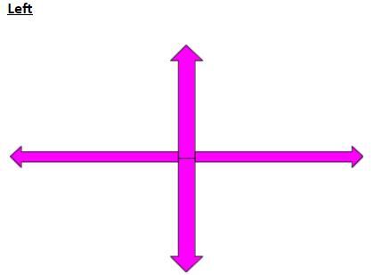
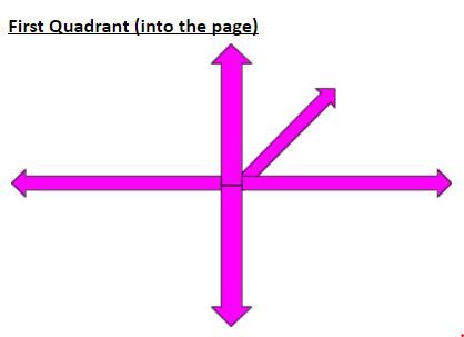
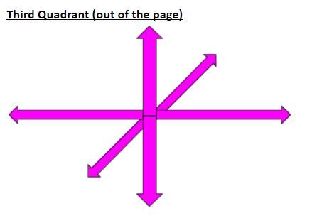
3. There are six ways to draw an axis of a coordinate frame.
Rules for Assigning Denavit-Hartenberg Frames
Here are the four rules that guide the drawing of the D-H coordinate frames:
- The z-axis is the axis of rotation for a revolute joint and the direction of motion for a prismatic joint.
- The x-axis must be perpendicular to both the current z-axis and the previous z-axis.
- The x-axis must intersect the previous z-axis (rule does not apply to frame 0).
- The y-axis is determined from the x-axis and z-axis by using the right-hand coordinate system.
For step-by-step examples of assigning Denavit-Hartenberg Frames, check out my tutorial here.
Examples
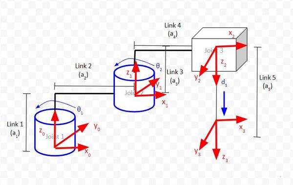
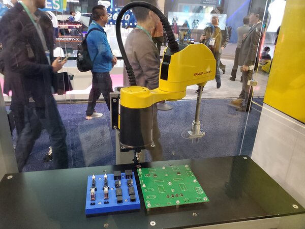
Here are D-H frames for a Scara robotic arm.
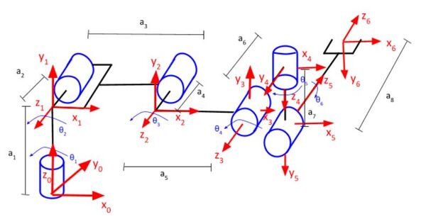
Here are the D-H frames for a six degree of freedom robot like the Universal Robots UR5.
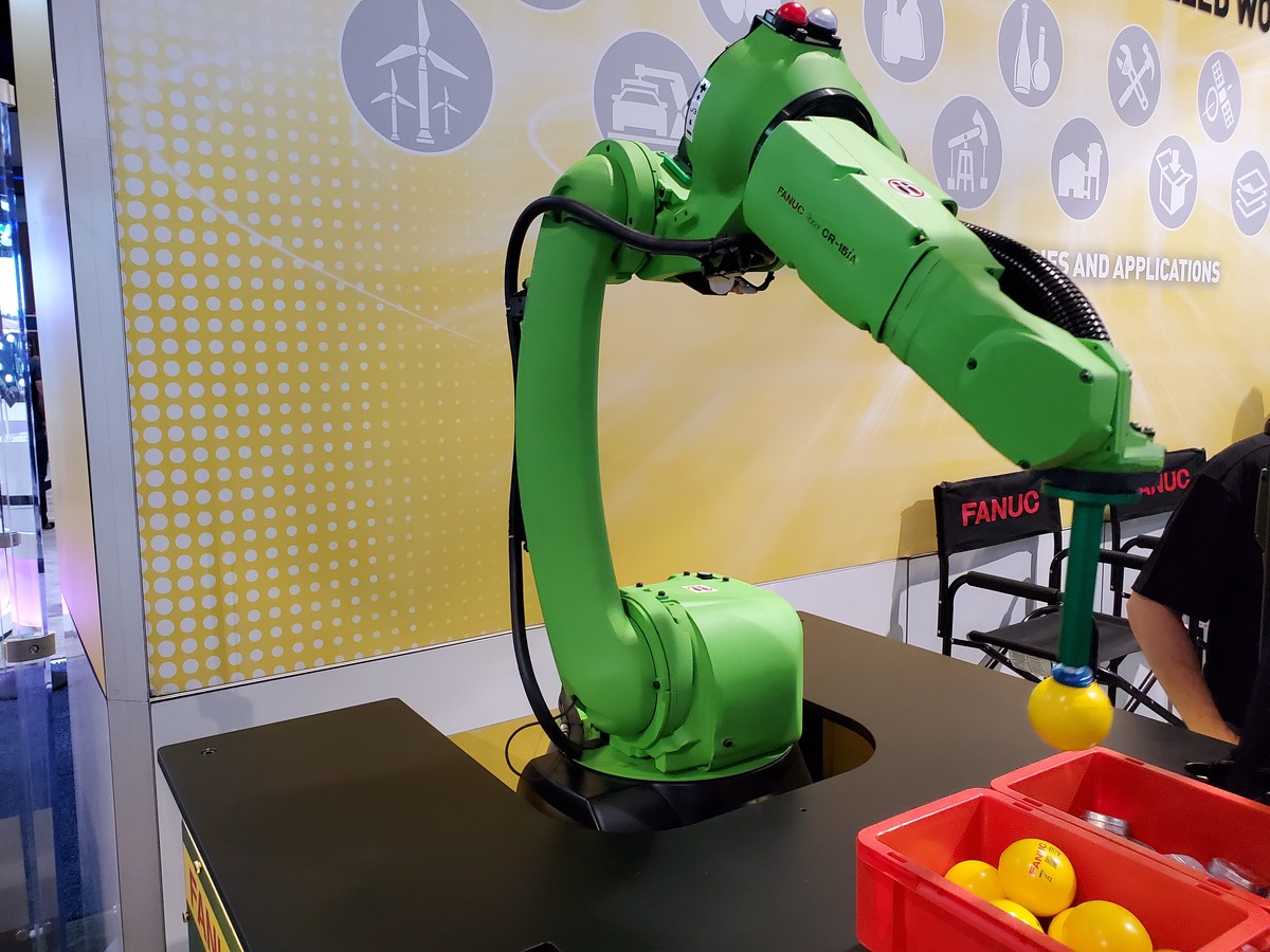
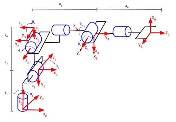
Here are the D-H frames for a six degree of freedom industrial robot like the FANUC LRMate 200iD.
Guidelines for Creating the Denavit-Hartenberg Parameter Table
Once you’ve finished drawing the Denavit-Hartenberg frames for a robotic arm, you then create the Denavit-Hartenberg parameter table. This table takes the following form:
- Number of Rows = Number of Frames – 1
- Number of Columns = 4: Two columns for rotation and two columns for displacement
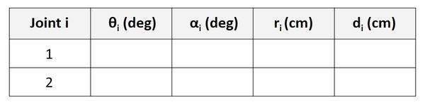
The Denavit-Hartenberg parameter tables consist of four variables:
- The two variables used for rotation are θ and α.
- The two variables used for displacement are r and d.
Consider two coordinate frames: Frame 1 and Frame 2. Let Frame 0 = Frame n-1 and Frame 1 = Frame n.
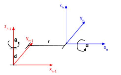
- θ is the angle from xn-1 to xn around zn-1.
- α is the angle from zn-1 to zn around xn.
- r (sometimes you’ll see the letter ‘a’ instead of ‘r’) is the distance between the origin of the n-1 frame and the origin of the n frame along the xn direction.
- d is the distance from xn-1 to xn along the zn-1 direction.
See step-by-step examples of how to create Denavit-Hartenberg Parameter tables.
Guidelines for Creating Homogeneous Transformation Matrices Using the Denavit-Hartenberg Parameter Table
Once we have filled in the Denavit-Hartenberg (D-H) parameter table for a robotic arm, we find the homogeneous transformation matrices (also known as the Denavit-Hartenberg matrix) by plugging the values into the matrix of the following form, which is the homogeneous transformation matrix for joint n (i.e. the transformation from frame n-1 to frame n).
homgen_n-1_n =
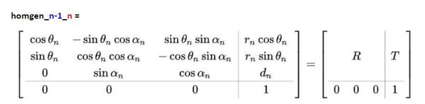
where R is the 3×3 submatrix in the upper left that represents the rotation from frame n-1 (e.g. frame 0) to frame n (e.g. frame 1), and T is the 3×1 submatrix in the upper right that represents the translation (or displacement) from frame n-1 to frame n.
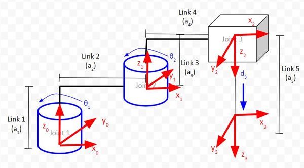
For example, suppose we have a SCARA robotic arm.
We draw the kinematic diagram for this arm.
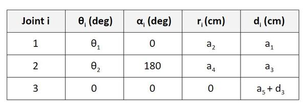
We then use that diagram to find the Denavit-Hartenberg parameters:
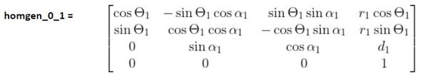
We now want to find the homogeneous transformation matrix from frame 0 to frame 1, so we look at the first row of the Denavit-Hartenberg parameter table labeled ‘Joint 1’ (remember that a joint in our case is either a servo motor that produces rotational motion or a linear actuator that produces linear motion).
In this case, n=1, and we would look at the first row of the D-H table (Joint 1) and plug in the appropriate values into the following matrix:
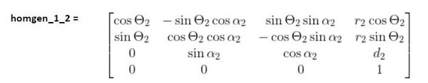
For the homogeneous transformation matrix from frame 1 to 2, we would look at the second row of the D-H table (Joint 2) and plug in the corresponding values into the following matrix.
For the homogeneous transformation matrix from frame 2 to 3, we would look at the third row of the table (Joint 3) and plug in the corresponding values into the following matrix.
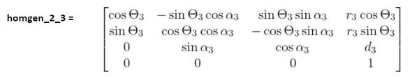
Then, to find the homogeneous transformation matrix from the base frame (frame 0) to the end-effector frame (frame 3), we would multiply all the transformation matrices together.
homgen_0_3 = (homgen_0_1)(homgen_1_2)(homgen_2_3)
See step-by-step examples of how to create Homogeneous Transformation Matrices Using Denavit-Hartenberg.
References
Sodemann, Dr. Angela 2020, RoboGrok, accessed 5 October 2020, <http://robogrok.com/>