
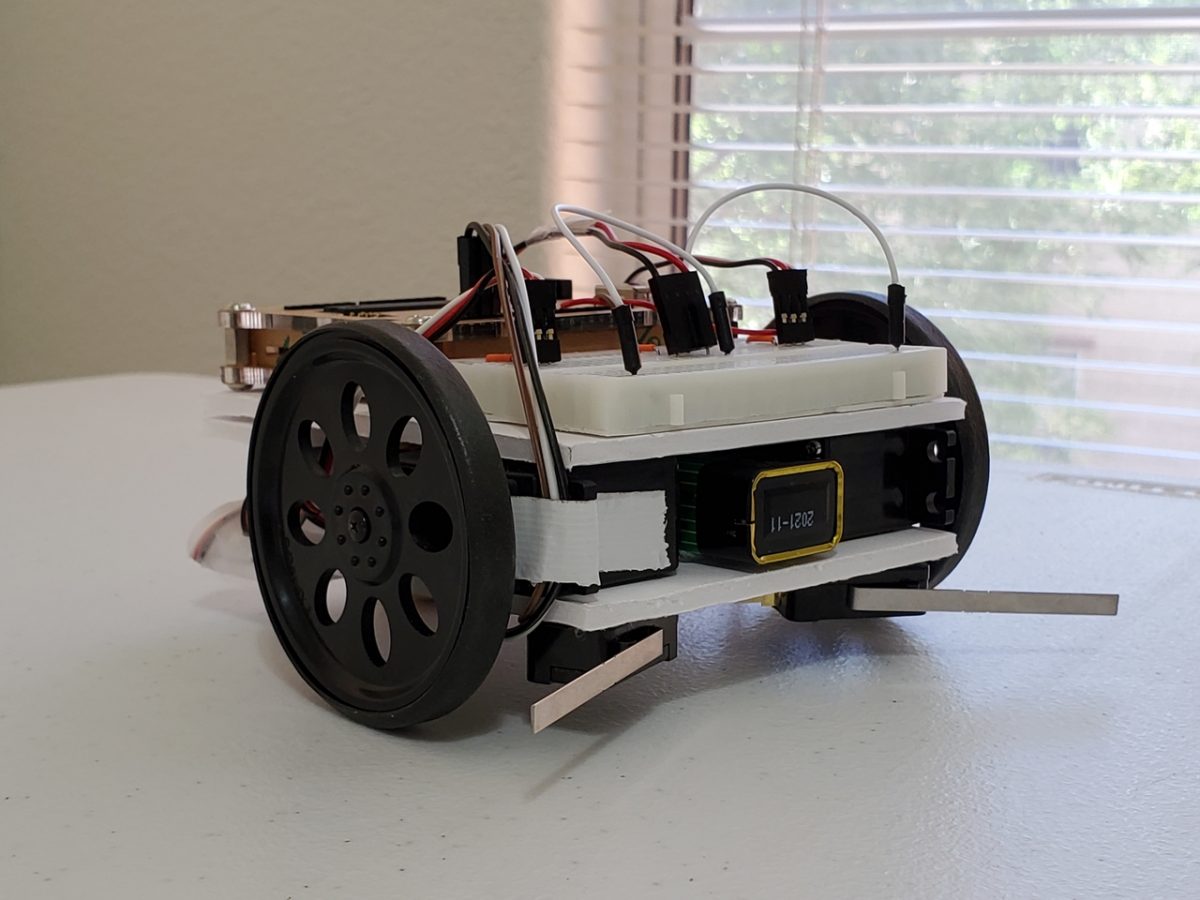
In this post, I’ll show you how to make an object detection robot using Arduino. This robot will move around a room and when it bumps into an object, it will turn around and go in another direction. Reminds me of the iRobot vacuum cleaner!
Shout out to the late Gordon McComb for this project idea. He is the author of an excellent book that I recommend buying if you’re getting started with robotics: How to Make a Robot.

Requirements
Here are the requirements:
- Make a robot that can turn around and go in a different direction after bumping into an object.
You Will Need
The following components are used in this project. You will need:
Directions
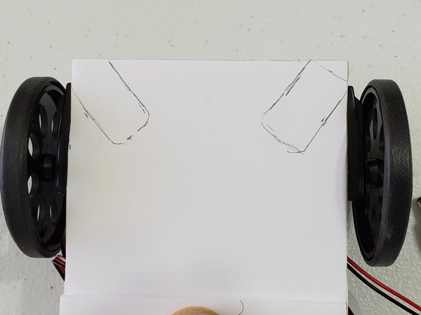
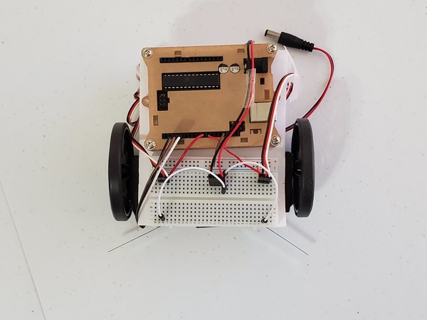
First, I position the snap action switches so that the corners are aligned with the side and front of the lower base of the robot. I will make a mark with a pencil to indicate where I should glue (we’ll glue them down later).
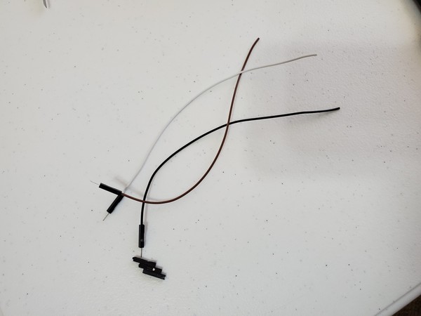
Grab three pieces of 6-inch male-to-female jumper wire.
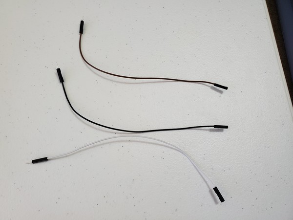
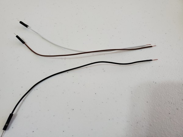
Cut off the female end of the jumper wire.
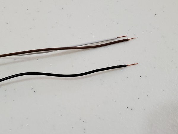
Remove 0.25 inches of insulation from the end of the wire that you just cut.
Twist the loose ends of each wire.
Before you solder, it is helpful to first stick the wire strands through the pinhole of the terminal.
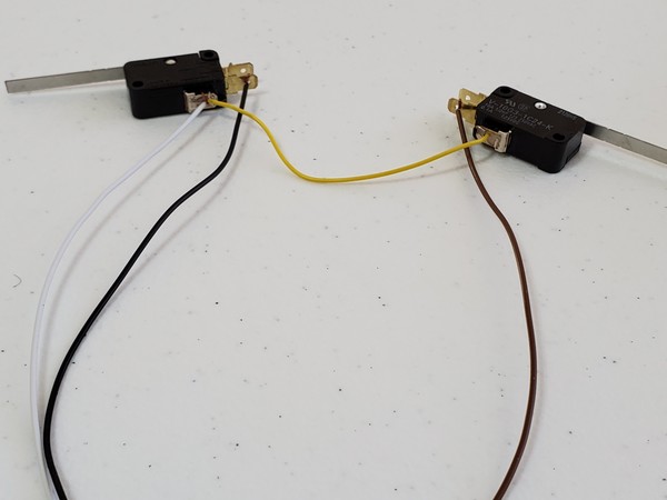
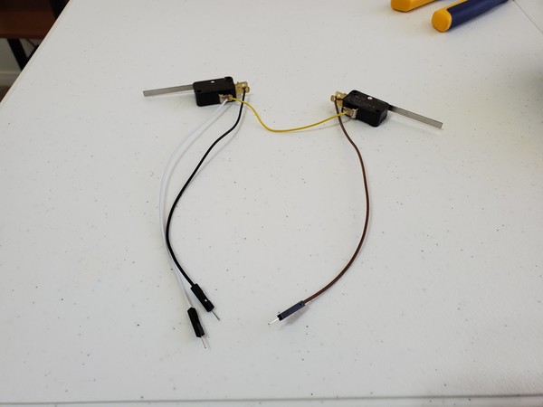
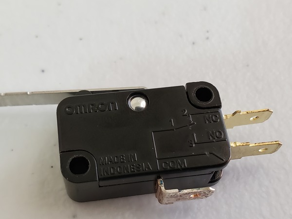
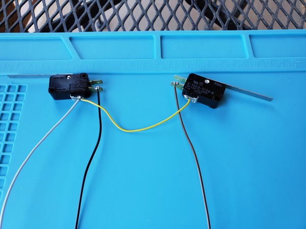
Solder one wire to the NO metal terminal of a switch (black wire).
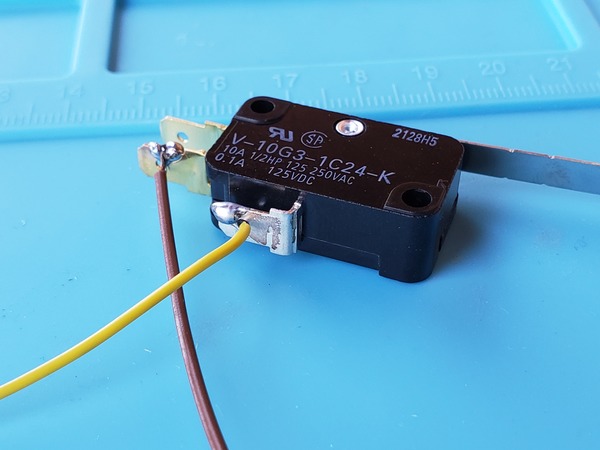
Solder one wire to the NO metal terminal of the other switch (brown wire).
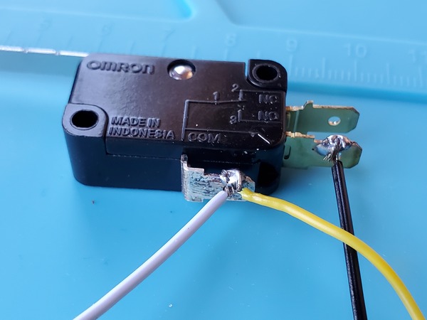
Solder one wire to the COM terminal of the switch that will go on the right side of the robot (white wire).
Get 3 inches of solder wire and connect the COM terminals of both switches (yellow wire).
If you don’t know how to solder, check out this video (skip to the soldering part):
Now we need to test the switches.
Plug the jumper connected to the Right switch COM into Digital Pin 4 on the Arduino.
Plug the jumper connected to the Right switch NO into Digital Pin 2 on the Arduino.
Plug the jumper connected to the Left switch NO into Digital Pin 3 on the Arduino.
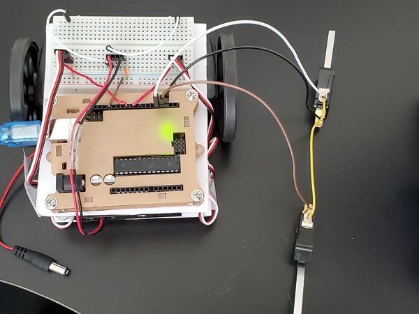
Now, upload the following code to the Arduino. When you press down one of the switches, the built-in LED on the Arduino should light up.
/**
 * This program is to test the snap action switches
 *
 * @author Addison Sears-Collins
 * @version 1.0 2019-05-12
 */

/*
 *  This setup code is run only once, when Arudino is
 *  supplied with power.
 */
void setup() {

  // Pin 13 is LED output
  pinMode(LED_BUILTIN, OUTPUT);

  pinMode(2, INPUT);  // Right Switch
  pinMode(3, INPUT);  // Left Switch
  pinMode(4, OUTPUT); // Ground for Switches

  digitalWrite(2, HIGH); // Enable pullup resistors
  digitalWrite(3, HIGH); // Enable pullup resistors
  digitalWrite(4, LOW);  // Set ground to 0 volts
}


/*
 * Light LED pin13 if pin 2 or 3 goes LOW (i.e. pressed)
 */
void loop() {
  if ((digitalRead(2) == LOW) || (digitalRead(3) == LOW))
    digitalWrite(LED_BUILTIN, HIGH);
  else
    digitalWrite(LED_BUILTIN, LOW);
  delay (100);
}
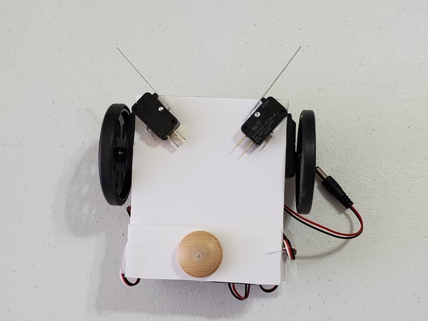
If everything is working OK, go ahead and glue the switches to the lower base of the board.

Now, upload the following sketch to the Arduino, and then place the Arduino on the floor.
#include <Servo.h>

/**
 *  This robot will move around a room and when it
 *  bumps into an object, it will turn around and
 *  go in another direction.
 *
 * @author Addison Sears-Collins
 * @version 1.0 2019-05-12
 */

// Create two servo objects, one for each wheel
Servo right_servo;
Servo left_servo;

// Volatile keyword is used because these variables
// can change at any time without any action having been
// taken by the compiled code.

volatile int left_switch = LOW;   // Left switch flag
volatile int right_switch = LOW;  // Right switch flag
boolean already_started = false;

/*
 *  This setup code is run only once, when Arudino is
 *  supplied with power.
 */
void setup() {
  // Set the pin modes for the switches
  pinMode(2, INPUT); // Right switch is input
  pinMode(3, INPUT); // Left switch is input
  pinMode(4, OUTPUT); // Pin 4 is ground

  // Turn on the internal pull up resistors for the switches
  // Keeps input from floating when the switches are not
  // pressed
  digitalWrite(2, HIGH);   // Right switch default to high
  digitalWrite(3, HIGH);   // Left switch default to high
  digitalWrite(4, LOW);    // Pin 4 default is ground

  right_servo.attach(9);    // Right servo is pin 9
  left_servo.attach(10);    // Left servo is pin 10

  // Declare the interrupts
  // attachInterrupt(digitalPinToInterrupt(pin), ISR, mode)
  // Interrupt when go from high to low
attachInterrupt(digitalPinToInterrupt(2), hit_right, FALLING);
attachInterrupt(digitalPinToInterrupt(3), hit_left, FALLING);

  already_started = true;  // Bot can now move
}

void loop() {
  if (left_switch == HIGH) {   // If the left switch is hit
    go_backwards();            // Go backwards for 1 sec
    delay(1000);
    go_right();             // Turn to the right for 1 sec
    delay(1000);
    go_forward();              // Move forward
    left_switch = LOW;         // Reset the flag
  }

  if (right_switch == HIGH) {  // If the right switch is hit
    go_backwards();           // Go backwards for one second
    delay(1000);
    go_left();                // Turn left for one second
    delay(1000);
    go_forward();             // Move forward
    right_switch = LOW;       // Reset the flag
  }
}

// Interrupt routine for left switch bumping into an object
void hit_left() {
  if (already_started)     // Valid if the program has begun
    left_switch = HIGH;    // Set flag high to get serviced
}

// Interrupt routine for right switch bumping into an object
void hit_right() {
  if (already_started)    // Valid if the program has begun
    right_switch = HIGH;  // Set flag high to get serviced
}

/*
 *  Forwards, backwards, right, left, stop.
 */
void go_forward() {
  right_servo.write(0);
  left_servo.write(180);
}
void go_backwards() {
  right_servo.write(180);
  left_servo.write(0);
}
void go_right() {
  right_servo.write(180);
  left_servo.write(180);
}
void go_left() {
  right_servo.write(0);
  left_servo.write(0);
}
/*
void stop_all() {
  right_servo.write(90); // Tweak the 90
  left_servo.write(90);  // Tweak the 90
}
*/
Power it up by turning on the servos:
- a13 to e3 = left servo ON
- e13 to e28 = right servo ON
Then plug in the Arduino’s power.
In order to actually start the program, you need to depress one of the switches. Make sure the Arduino is on the floor before you start the program.
Watch the Object Detection Robot move!
Video