
In this tutorial, I’ll show you how to convert camera pixels to real-world coordinates (in centimeters). A common use case for this is in robotics (e.g. along a conveyor belt in a factory) where you want to pick up an object from one location and place it in another location using nothing but a robotic arm and an overhead camera.
Prerequisites
To complete this tutorial, it is helpful if you have completed the following prerequisites. If you haven’t that is fine. You can still follow the process I will explain below.
- You have set up Raspberry Pi with the Raspbian Operating System.
- You have OpenCV and a Raspberry Camera Module Installed.
- You know how to determine the pixel location of an object in a real-time video stream.
- You completed this tutorial to build a two degree of freedom robotic arm (Optional). My eventual goal is to be able to move this robotic arm to the location of an object that is placed somewhere in its workspace. The location of the object will be determined by the overhead Raspberry Pi camera.
You Will Need
Here are some extra components you’ll need if you want to follow along with the physical setup we put together in the prerequisites (above).
- 1 x VELCRO Brand Thin Clear Mounting Squares 12-pack | 7/8 Inch (you can also use Scotch tape).
- 1 x Overhead Video Stand Phone Holder
- 10 x 1cm Grid Write N Wipe Boards (check eBay….also search Amazon for ‘Centimeter Grid Dry Erase Board’)
- 1 x Ruler that can measure in centimeters (or measuring tape)
Mount the Camera Module on the Overhead Video Stand Phone Holder (Optional)
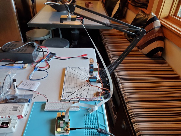
Grab the Overhead Video Stand Phone Holder and place it above the grid like this.
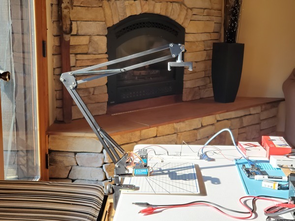
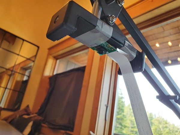
Using some Velcro adhesives or some tape, attach the camera to the holder’s end effector so that it is pointing downward towards the center of the grid.
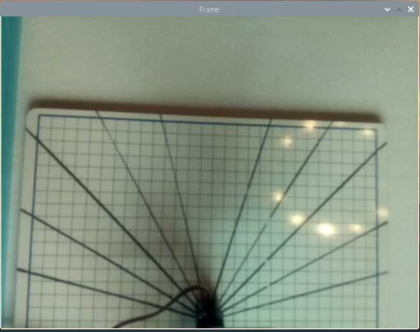
Here is how my video feed looks.
I am running the program on this page (test_video_capture.py). I’ll retype the code here:
# Credit: Adrian Rosebrock
# https://www.pyimagesearch.com/2015/03/30/accessing-the-raspberry-pi-camera-with-opencv-and-python/

# import the necessary packages
from picamera.array import PiRGBArray # Generates a 3D RGB array
from picamera import PiCamera # Provides a Python interface for the RPi Camera Module
import time # Provides time-related functions
import cv2 # OpenCV library

# Initialize the camera
camera = PiCamera()

# Set the camera resolution
camera.resolution = (640, 480)

# Set the number of frames per second
camera.framerate = 32

# Generates a 3D RGB array and stores it in rawCapture
raw_capture = PiRGBArray(camera, size=(640, 480))

# Wait a certain number of seconds to allow the camera time to warmup
time.sleep(0.1)

# Capture frames continuously from the camera
for frame in camera.capture_continuous(raw_capture, format="bgr", use_video_port=True):

    # Grab the raw NumPy array representing the image
    image = frame.array

    # Display the frame using OpenCV
    cv2.imshow("Frame", image)

    # Wait for keyPress for 1 millisecond
    key = cv2.waitKey(1) & 0xFF

    # Clear the stream in preparation for the next frame
    raw_capture.truncate(0)

    # If the `q` key was pressed, break from the loop
    if key == ord("q"):
        break
What is Our Goal?
Assuming you’ve completed the prerequisites, you know how to find the location of an object in the field of view of a camera, and you know how to express that location in terms of the pixel location along both the x-axis (width) and y-axis (height) of the video frame.
In a real use case, if we want a robotic arm to automatically pick up an object that enters its workspace, we need some way to tell the robotic arm where the object is. In order to do that, we have to convert the object’s position in the camera reference frame to a position that is relative to the robotic arm’s base frame.
Once we know the object’s position relative to the robotic arm’s base frame, all we need to do is to calculate the inverse kinematics to set the servo motors to the angles that will enable the end effector of the robotic arm to reach the object.
What is the Field of View?
Before we get started, let’s take a look at what field of view means.
The field of view for our Raspberry Pi camera is the extent of the observable world that it can see at a given point in time.
In the figure below, you can see a schematic of the setup I have with the Raspberry Pi. In this perspective, we are in front of the Raspberry Pi camera.
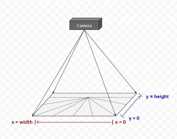
In the Python code, we set the size of the video frame to be 640 pixels in width and 480 pixels in height. Thus, the matrix that describes the field of view of our camera has 480 rows and 640 columns.
From the perspective of the camera (i.e. camera reference frame), the first pixel in an image is at (x=0, y=0), which is in the far upper-left. The last pixel (x = 640, y = 480) is in the far lower-right.
Calculate the Centimeter to Pixel Conversion Factor
The first thing you need to do is to run test_video_capture.py.
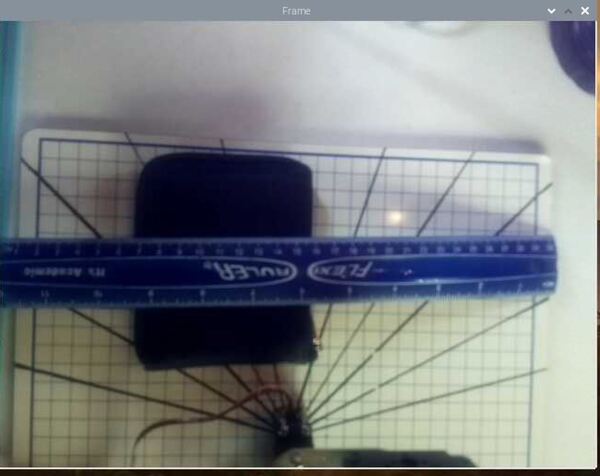
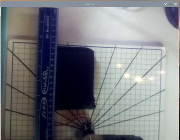
Now, grab a ruler and measure the width of the frame in centimeters. It is hard to see in the image below, but my video frame is about 32 cm in width.
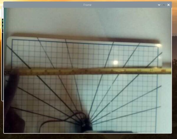
We know that in pixel units, the frame is 640 pixels in width.
Therefore, we have the following conversion factor from centimeters to pixels:
32 cm / 640 pixels = 0.05 cm / pixel
We will assume the pixels are square-shaped and the camera lens is parallel to the underlying surface so we can use the same conversion factor for both the x (width) and y (height) axes of the camera frame.
When you’re done, you can close down test_video_capture.py.
Test Your Conversion Factor
Now, let’s test this conversion factor of 0.05 cm / pixel.
Write the following code in your favorite Python IDE or text editor (I’m using Gedit).
This program is the absolute_difference_method.py code we wrote on this post with some small changes. This code detects an object and then prints its center to the video frame. I called this program absolute_difference_method_cm.py.
# Author: Addison Sears-Collins
# Description: This algorithm detects objects in a video stream
#   using the Absolute Difference Method. The idea behind this
#   algorithm is that we first take a snapshot of the background.
#   We then identify changes by taking the absolute difference
#   between the current video frame and that original
#   snapshot of the background (i.e. first frame).

# import the necessary packages
from picamera.array import PiRGBArray # Generates a 3D RGB array
from picamera import PiCamera # Provides a Python interface for the RPi Camera Module
import time # Provides time-related functions
import cv2 # OpenCV library
import numpy as np # Import NumPy library

# Initialize the camera
camera = PiCamera()

# Set the camera resolution
camera.resolution = (640, 480)

# Set the number of frames per second
camera.framerate = 30

# Generates a 3D RGB array and stores it in rawCapture
raw_capture = PiRGBArray(camera, size=(640, 480))

# Wait a certain number of seconds to allow the camera time to warmup
time.sleep(0.1)

# Initialize the first frame of the video stream
first_frame = None

# Create kernel for morphological operation. You can tweak
# the dimensions of the kernel.
# e.g. instead of 20, 20, you can try 30, 30
kernel = np.ones((20,20),np.uint8)

# Centimeter to pixel conversion factor
# I measured 32.0 cm across the width of the field of view of the camera.
CM_TO_PIXEL = 32.0 / 640

# Capture frames continuously from the camera
for frame in camera.capture_continuous(raw_capture, format="bgr", use_video_port=True):

    # Grab the raw NumPy array representing the image
    image = frame.array

    # Convert the image to grayscale
    gray = cv2.cvtColor(image, cv2.COLOR_BGR2GRAY)

    # Close gaps using closing
    gray = cv2.morphologyEx(gray,cv2.MORPH_CLOSE,kernel)

    # Remove salt and pepper noise with a median filter
    gray = cv2.medianBlur(gray,5)

    # If first frame, we need to initialize it.
    if first_frame is None:

      first_frame = gray

      # Clear the stream in preparation for the next frame
      raw_capture.truncate(0)

      # Go to top of for loop
      continue

    # Calculate the absolute difference between the current frame
    # and the first frame
    absolute_difference = cv2.absdiff(first_frame, gray)

    # If a pixel is less than ##, it is considered black (background).
    # Otherwise, it is white (foreground). 255 is upper limit.
    # Modify the number after absolute_difference as you see fit.
    _, absolute_difference = cv2.threshold(absolute_difference, 50, 255, cv2.THRESH_BINARY)

    # Find the contours of the object inside the binary image
    contours, hierarchy = cv2.findContours(absolute_difference,cv2.RETR_TREE,cv2.CHAIN_APPROX_SIMPLE)[-2:]
    areas = [cv2.contourArea(c) for c in contours]

    # If there are no countours
    if len(areas) < 1:

      # Display the resulting frame
      cv2.imshow('Frame',image)

      # Wait for keyPress for 1 millisecond
      key = cv2.waitKey(1) & 0xFF

      # Clear the stream in preparation for the next frame
      raw_capture.truncate(0)

      # If "q" is pressed on the keyboard,
      # exit this loop
      if key == ord("q"):
        break

      # Go to the top of the for loop
      continue

    else:

      # Find the largest moving object in the image
      max_index = np.argmax(areas)

    # Draw the bounding box
    cnt = contours[max_index]
    x,y,w,h = cv2.boundingRect(cnt)
    cv2.rectangle(image,(x,y),(x+w,y+h),(0,255,0),3)

    # Draw circle in the center of the bounding box
    x2 = x + int(w/2)
    y2 = y + int(h/2)
    cv2.circle(image,(x2,y2),4,(0,255,0),-1)

    # Calculate the center of the bounding box in centimeter coordinates
    # instead of pixel coordinates
    x2_cm = x2 * CM_TO_PIXEL
    y2_cm = y2 * CM_TO_PIXEL

    # Print the centroid coordinates (we'll use the center of the
    # bounding box) on the image
    text = "x: " + str(x2_cm) + ", y: " + str(y2_cm)
    cv2.putText(image, text, (x2 - 10, y2 - 10),
      cv2.FONT_HERSHEY_SIMPLEX, 0.5, (0, 255, 0), 2)

    # Display the resulting frame
    cv2.imshow("Frame",image)

    # Wait for keyPress for 1 millisecond
    key = cv2.waitKey(1) & 0xFF

    # Clear the stream in preparation for the next frame
    raw_capture.truncate(0)

    # If "q" is pressed on the keyboard,
    # exit this loop
    if key == ord("q"):
      break

# Close down windows
cv2.destroyAllWindows()
To get the object’s center in centimeter coordinates rather than pixel coordinates, we had to add the cm-to-pixel conversion factor to our code.
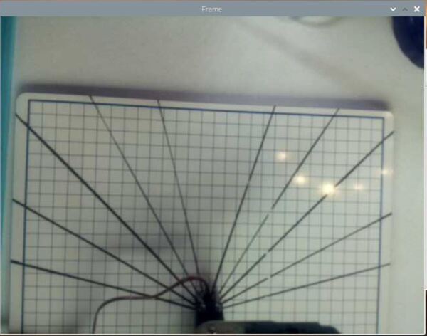
When you first launch the code, be sure there are no objects in the field of view and that the camera is not moving. Also, make sure that the level of light is fairly uniform across the board with no moving shadows (e.g. such as from the sun shining through a nearby window). Then place an object in the field of view and record the object’s x and y coordinate.
Here is the camera output when I first run the code:
Here is the output after I place my wallet in the field of view:
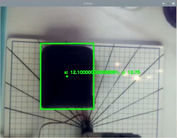
- x-coordinate of the wallet in centimeters: 12.1 cm
- y-coordinate of the wallet in centimeters: 12.75 cm
Get a ruler, and measure the object’s x coordinate (measure from the left-side of the camera frame) in centimeters, and see if that matches up with the x-value printed to the camera frame.
Get a ruler, and measure the object’s y coordinate (measure from the top of the camera frame) in centimeters, and see if that matches up with the y-value printed to the camera frame.
The measurements should match up pretty well.
That’s it. Keep building!
References
Credit to Professor Angela Sodemann for teaching me this stuff. Dr. Sodemann is an excellent teacher (She runs a course on RoboGrok.com).