In this post, I will explain the difference between the Robot State Publisher and the Joint State Publisher ROS packages.
In order to understand the difference between the packages, it is important you first understand that every robot is made up of two components:
- Joints
- Links
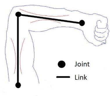
Links and Joints in Robotics
Links are the rigid pieces of a robot. They are the “bones”.
Links are connected to each other by joints. Joints are the pieces of the robot that move, enabling motion between connected links.
Consider the human arm below as an example. The shoulder, elbow, and wrist are joints. The upper arm, forearm and palm of the hand are links.
For a robotic arm, links and joints look like this.
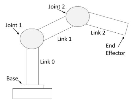
You can see that a robotic arm is made of rigid pieces (links) and non-rigid pieces (joints). Servo motors at the joints cause the links of a robotic arm to move.
For a mobile robot with LIDAR, links and joints look like this:
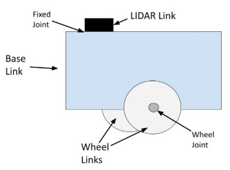
The wheel joints are revolute joints. Revolute joints cause rotational motion. The wheel joints in the photo connect the wheel link to the base link.
Fixed joints have no motion at all. You can see that the LIDAR is connected to the base of the robot via a fixed joint (i.e. this could be a simple screw that connects the LIDAR to the base of the robot).
You can also have prismatic joints. The SCARA robot in this post has a prismatic joint. Prismatic joints cause linear motion between links (as opposed to rotational motion).
Difference Between the Robot State Publisher and the Joint State Publisher
Whenever we want a robot to complete a specific task (e.g. move a certain distance in an environment, pick up an object, etc.), we have to have a way to know the position and velocity of each joint at all times. The Joint State Publisher does exactly this.
The Joint State Publisher package keeps track of the position (i.e. angle in radians for a servo motor or displacement in meters for a linear actuator) and velocity of each joint of a robot and publishes these values to the ROS system as sensor_msgs/JointState messages.
The Robot State Publisher then takes two main inputs:
- The sensor_msgs/JointState messages from the Joint State Publisher.
- A model of the robot in URDF file format.
The Robot State Publisher takes that information, outputs the position and orientation of each coordinate frame of the robot, and publishes this data to the tf2 package.
The tf2 package is responsible for keeping track of the position and orientation of all coordinate frames of a robot over time. At any given time, you can query the tf2 package to find out the position and orientation of any coordinate frame (i.e. “child frame”) relative to another coordinate frame (i.e. “parent” frame).
For example, if we are using ROS 2 and want to know the position and orientation of the LIDAR link relative to the base of the robot, we would use the following command:
ros2 run tf2_ros tf2_echo base_link lidar_link
The syntax is:
ros2 run tf2_ros tf2_echo <parent frame> <child frame>
Joint State Publisher: Simulation vs. Real World
When you are creating robots in simulation using a tool like Gazebo, you are going to want to use the joint state publisher Gazebo plugin to publish the position and orientation of the joints (i.e. publish the sensor_msgs/JointState messages).
In a real-world robotics project, you will want to write your own joint state publisher. You can find examples of how to do this here, here, and here.