

In this tutorial, I will show you how to set up the ROS Navigation Stack for a robot in simulation.
Credit to Ramkumar Gandhinathan and Lentin Joseph’s awesome book ROS Robotics Projects Second Edition (Disclosure: As an Amazon Associate I earn from qualifying purchases). I highly recommend it if you want to learn ROS 1. Many of the files in this tutorial (URDF, configuration, and STL files), come from their book’s public GitHub page.
What is the ROS Navigation Stack?
The ROS Navigation Stack is a collection of software packages that you can use to help your robot move from a starting location to a goal location safely.
The official steps for setup and configuration are at this link on the ROS website, but we will walk through everything together, step-by-step, because those instructions leave out a lot of detail.
IMPORTANT: For your reference, all our code will be located in this folder, which I named simulated_home_delivery_robot.
Real-World Applications
This project has a number of real-world applications:
- Indoor and Outdoor Delivery Robots
- Room Service Robots
- Robot Vacuums
- Order Fulfillment
- Manufacturing
- Factories
We will create a robot that will exist in a world that contains a post office and three houses. The use case for this simulated robot would be picking up packages at a post office and delivering them to houses in a neighborhood.
Let’s get started!
Prerequisites
- You have completed this tutorial where you learned how to create a simulated mobile manipulator.
Create a ROS Package
Let’s create a ROS package.
In a new terminal window, move to the src (source) folder of your workspace.
cd ~/catkin_ws/srcNow create the package.
catkin_create_pkg mobile_manipulator actionlib roscpp rospy std_msgscd ~/catkin_ws/catkin_make --only-pkg-with-deps mobile_manipulatorSet Up the World
Create a new folder called worlds inside the mobile_manipulator package.
roscd mobile_manipulatormkdir worldscd worldsOpen a new file called postoffice.world.
gedit postoffice.worldDownload, and then add this code.
Save the file and close it.
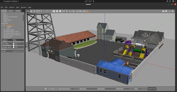
Let’s visualize this world using Gazebo.
gazebo postoffice.world
On my computer, this file took five minutes to load, so be patient.
When you want to close Gazebo, type CTRL + C in all terminal windows to close everything down.
Make a note of the location of this world file. We’ll need it later. Type:
pwdThe path on my computer is:
/home/focalfossa/catkin_ws/src/mobile_manipulator/worlds/postoffice.worldNow open a new terminal window, and type:
roscd mobile_manipulatormkdir launchNow, go get your launch file from this tutorial. The name of my launch file is mobile_manipulator_gazebo.launch. I can access this file by opening a new terminal window, and typing:
roscd mobile_manipulator_body/launch/Take that launch file and put it in the following directory:
roscd mobile_manipulator/launch/Within the ~/mobile_manipulator/launch/ directory, open the launch file.
gedit mobile_manipulator_gazebo.launchYour launch file should look like the following. You will notice that we added the post office world file.
Save the file, and close it.
Launch the Robot in the Gazebo World
Now let’s launch the robot in Gazebo.
Move to your catkin workspace.
cd ~/catkin_ws/roslaunch mobile_manipulator mobile_manipulator_gazebo.launchHere is my output:
Add a LIDAR
Create the Code
Now that we have set up the environment, let’s add a LIDAR to our robot so that it can perform SLAM (Simultaneous Localization And Mapping) within the post office world.
Open a new terminal window. Type the following command.
roscd mobile_manipulator_body/urdf/Open mobile_manipulator.urdf.
gedit mobile_manipulator.urdfMake sure your file has this code. Add the code between the ARM block and the BASE TRANSMISSIONS block.
You will see that we have added the LIDAR (i.e. laser_link), and we have also added a Gazebo plugin for it.
Save and close the file.
Test the LIDAR
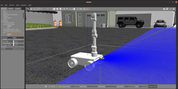
Now let’s launch the robot in Gazebo.
Open a new terminal window, and move to your catkin workspace.
cd ~/catkin_ws/roslaunch mobile_manipulator mobile_manipulator_gazebo.launchHere is my output:
To see the active coordinate frames, type the following command:
rosrun tf2_tools view_frames.pyTo open the pdf file that shows the coordinate frames, type the following command:
evince frames.pdfConfigure the ROS Navigation Stack Parameters
Now that we have set up the world and added a LIDAR to our robot, we can set up and configure the ROS Navigation Stack so that our simulated robot can move autonomously through the environment.
Open a new terminal window.
Move to your package.
roscd mobile_manipulatorCreate a new folder. We want this folder to hold the configuration parameters.
mkdir paramcd paramThe ROS Navigation Stack uses two costmaps to store information about obstacles in the world.
- Global costmap: This costmap is used to generate long term plans over the entire environment….for example, to calculate the shortest path from point A to point B on a map.
- Local costmap: This costmap is used to generate short term plans over the environment….for example, to avoid obstacles.
We have to configure these costmaps for our project. We set the configurations in .yaml files.
Common Configuration (Global and Local Costmap)
Let’s create a configuration file that will house parameters that are common to both the global and the local costmap. The name of this file will be costmap_common_params.yaml.
gedit costmap_common_params.yamlAdd the costmap_common_params.yaml code to this file.
Save and close the file.
To learn more about each of the parameters and what they mean, check out this link.
Global Configuration (Global Costmap)
Let’s create a configuration file that will house parameters for the global costmap. The name of this file will be global_costmap_params.yaml.
gedit global_costmap_params.yamlAdd the global_costmap_params.yaml code to this file.
Save and close the file.
Local Configuration (Local Costmap)
Let’s create a configuration file that will house parameters for the local costmap. The name of this file will be local_costmap_params.yaml.
gedit local_costmap_params.yamlAdd the local_costmap_params.yaml code to this file.
Save and close the file.
Base Local Planner Configuration
In addition to the costmap configurations we did in the previous section, we need to configure ROS Navigation Stack’s base local planner. The base_local_planner computes velocity commands that are sent to the robot base controller. The values that you use for your base_local_planner will depend on your robot.
gedit base_local_planner_params.yamlAdd the base_local_planner_params.yaml code to this file.
Save and close the file.
Configure RViz Settings
Add this file named mobile_manipulator.rviz to the param folder of your package.
roscd mobile_manipulator/paramInstall the ROS Navigation Stack
Open a terminal window, and type the following command:
sudo apt-get install ros-noetic-navigationTo see if it installed correctly, type:
rospack find amclYou should see the following output:
/opt/ros/noetic/share/amclTune the AMCL Parameters
Open up your AMCL node.
roscd amcl/examplesOpen the amcl_diff.launch file.
sudo gedit amcl_diff.launchHere is my amcl_diff.launch file.
Set the following parameters, save the file, and close it.
<param name="odom_model_type" value="diff-corrected"/> <param name="odom_alpha1" value="0.005"/> <param name="odom_alpha2" value="0.005"/> <param name="odom_alpha3" value="0.010"/> <param name="odom_alpha4" value="0.005"/> <param name="odom_alpha5" value="0.003"/> Press CTRL + C in all windows to close everything down.
Create a Map Using the ROS Hector-SLAM Package
Let’s create a map using the ROS Hector-SLAM package. For more information on this package, check this post.
Install Qt4
Install Qt4. Qt4 is a software that is used to generate graphical user interfaces.
sudo add-apt-repository ppa:rock-core/qt4sudo apt updatesudo apt-get install qt4-qmake qt4-dev-toolsType Y and press Enter to complete the installation. The whole process should take a while, so just be patient.
Download the Hector-SLAM Package
Move to your catkin workspace’s source folder.
cd ~/catkin_ws/srcClone the Hector-SLAM package into your workspace.
git clone https://github.com/tu-darmstadt-ros-pkg/hector_slam.gitSet the Coordinate Frame Parameters
We need to set the frame names and options correctly.
Go to the launch file for Hector-SLAM. All of this below is a single command, so you can just copy and paste.
sudo gedit ~/catkin_ws/src/hector_slam/hector_mapping/launch/mapping_default.launchSearch for these lines (lines 5 and 6 in my code).
<arg name="base_frame" default="base_footprint"/> <arg name="odom_frame" default="nav"/> Change those lines to this:
<arg name="base_frame" default="base_link"/> <arg name="odom_frame" default="odom"/> Now go to the end of this file, and find these lines (line 54 in my code).
<node pkg="tf" type="static_transform_publisher" name="base_to_laser_broadcaster" args="0 0 0 0 0 0 base_link laser_link 100"/> Save the file, and return to the terminal window.
Open a new terminal window, and type this command:
cd ~/catkin_ws/Build the packages.
catkin_make --only-pkg-with-deps hector_slamIf you see this error message…
Project ‘cv_bridge’ specifies ‘/usr/include/opencv’ as an include dir, which is not found. It does neither exist as an absolute directory nor in…Type:
cd /usr/includesudo ln -s opencv4/ opencvBuild the packages again.
catkin_make --only-pkg-with-deps hector_slamWait a minute or two while the Hector-SLAM package builds.
Launch Mapping
Open a new terminal, and type the following command:
roslaunch mobile_manipulator mobile_manipulator_gazebo.launchNow launch the mapping process.
roslaunch hector_slam_launch tutorial.launchYou can steer the robot by opening a new window and typing:
rosrun rqt_robot_steering rqt_robot_steeringMove the robot around the environment slowly. Map-making works best at slow (EXTREMELY slow) speeds.
I recommend the following sequence of actions:
- Move the robot backwards at 0.03 meters per second (i.e. -0.03 m/s).
- Turn the robot 90 degrees in-place at a rate of -0.24 radians per second.
- Move the robot forward at a rate of 0.03 meters per second.
- Move the robot backwards at 0.03 meters per second.
Let’s save the map using a package called map_server. This package will save map data to a yaml and pgm formatted file.
Install map_server.
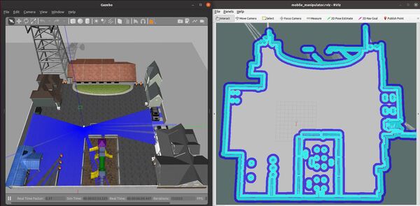
roscd mobile_manipulator/mapssudo apt-get install ros-noetic-map-serverWhen you are happy with the map that you see in rviz, you can save the map as test.yaml and test.pgm. Open a new terminal, and type:
roscd mobile_manipulator/mapsrosrun map_server map_saver -f testMaps will save to the ~…mobile_manipulator/maps directory.
Press CTRL + C on all terminal windows to shut everything down.
Load a Saved Map
To view the map, you can run the following command in a new terminal window to get the ROS Master started.
roscd mobile_manipulator/mapsroscoreNow load the map. In a new terminal window, type:
rosrun map_server map_server test.yamlOpen rviz in another terminal.
rvizClick Add in the bottom left, and add the Map display.
Under Topic under the Map section, select /map.
You should see the saved map on your screen.
Create a Preliminary Launch File
At this stage, we want to create a preliminary ROS launch file. This file will enable us to launch our mobile manipulator with the necessary mapping software as well as the move base and Adaptive Monte Carlo Localization (AMCL) nodes. You can learn more about the move base and AMCL nodes in this tutorial.
Type the following command.
roscd mobile_manipulator/launch
Create the following launch file.
gedit mobile_manipulator_move_base.launch
Add this code to the file.
Save the file, and close it.
Add an Inertial Measurement Unit (IMU) to the Robot
Let’s add an IMU sensor to our robot. IMUs can help us get more accurate localization.
Open a new terminal window. Type the following command.
roscd mobile_manipulator_body/urdf/
Open mobile_manipulator.urdf.
gedit mobile_manipulator.urdf
Make sure your file has the IMU code inside the SENSORS block right after the code for the laser_link.
Save and close the file.
Test the IMU
Now let’s launch the robot in Gazebo.
Open a new terminal window, and move to your catkin workspace.
cd ~/catkin_ws/
roslaunch mobile_manipulator mobile_manipulator_gazebo.launch
Open a new terminal, and type:
rostopic list
You should see a topic named /imu_data.
Set Up the robot_pose_ekf Package
Now we will install the robot_pose_ekf package. This package uses an extended Kalman filter to help us estimate the position and orientation of the robot from sensor data.
Getting Started
Open a new terminal window, and type:
sudo apt-get install ros-noetic-robot-pose-ekf
Now move to your workspace.
cd ~/catkin_ws
Build the package.
catkin_make
Add the the robot_pose_ekf node to a ROS Launch File
To launch the robot_pose_ekf node, you will need to add it to a launch file. Before we do that, let’s talk about the robot_pose_ekf node.
About the robot_pose_ekf Node
The robot_pose_ekf node will subscribe to the following topics (ROS message types are in parentheses):
- /odom : Position and velocity estimate based on the information from the wheel encoder tick counts. The orientation is in quaternion format. (nav_msgs/Odometry)
- /imu_data : Data from the Inertial Measurement Unit (IMU) sensor (sensor_msgs/Imu.msg)
This node will publish data to the following topics:
- /robot_pose_ekf/odom_combined : The output of the filter…the estimated 3D robot pose (geometry_msgs/PoseWithCovarianceStamped)
You might now be asking, how do we give the robot_ekf_pose node the data it needs?
The data for /odom will come from the /base_truth_odom topic which is declared inside the URDF file for the robot.
The data for /imu_data will come from the /imu_data topic which is also declared inside the URDF file for the robot. However, in this simulation, I will not use the IMU data since we are using Gazebo ground truth for the odometry. If you want to use the IMU data, you will set that parameter to true inside the launch file section for the robot_pose_ekf code.
In the launch file, we need to remap the data coming from the /base_truth_odom topic since the robot_pose_ekf node needs the topic name to be /odom.
Update the Launch File
Here is my full launch file. You will see that I have added static transform publishers at the top to get the data from base_footprint to base_link.
Launch the Autonomous Mobile Robot!
Let’s test to see if autonomous navigation is working.
Now, open a new terminal window, and type:
roslaunch mobile_manipulator mobile_manipulator_gazebo.launch
Then in another terminal window, type:
roslaunch mobile_manipulator mobile_manipulator_move_base.launch
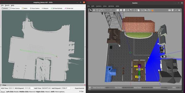
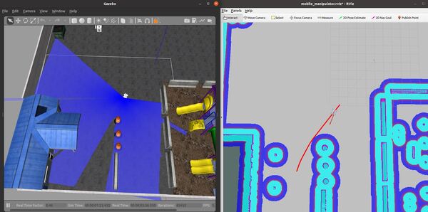
You set a pose estimate inside the map by clicking the 2D Pose Estimate button in Rviz and placing the estimate somewhere in line with where the robot currently is on the map.
Then you set the goal by clicking the Nav Goal button in Rviz and placing the goal in an empty space on the map.
The path will be drawn as a red line, and the robot will attempt to move to the goal location due to the velocity commands published by the move_base node.
To see the active coordinate frames, type the following command:
rosrun tf2_tools view_frames.py
To open the pdf file that shows the coordinate frames, type the following command:
evince frames.pdf
If you have difficulties, check out the differential drive control parameters in your control.yaml file. You can tweak the wheel_separation, wheel_radius, and velocity parameters inside this file by typing the following command:
roscd mobile_manipulator_body/config
gedit control.yaml
You can also tweak the velocity settings in your base_local_planner_params.yaml file and the footprint in the costmap_common_params.yaml file.
That’s it. Keep building!