
One of the most confusing concepts creating a robot for simulation using ROS 2 and Gazebo is how to set up the coordinate frames for links and joints for your robot using URDF and SDF.
In this tutorial, I will compare and contrast how poses of links and joints are defined inside a typical URDF file vs. an SDF file.
Prerequisites
You understand coordinate frames for mobile robots.
What is a URDF File?
URDF (Unified Robotic Description Format) is an XML file format used in ROS to describe all elements (links and joints) of a robot.
You can find my instructions for setting up a URDF file in this tutorial.
What is an SDF File?
SDF (Simulation Description Format) is an XML file format used in Gazebo to describe all elements (links and joints) of a robot.
You can find my instructions for setting up an SDF file in this tutorial.
Links and Joints: URDF
Let’s look at an example to make this easier to undestand.
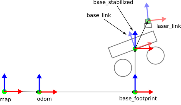
We will create a base for a basic mobile robot (like the one in the cover image of this tutorial) using URDF format. We will assume that the base_link coordinate frame is located 0.2 meters above the base_footprint coordinate frame. A sample schematic of the architecture is below.
Below is sample URDF code. We define the base_footprint link and the base_link.
<?xml version="1.0" ?>
<robot name="my_robot" xmlns:xacro="http://ros.org/wiki/xacro">
<!-- ****************** ROBOT BASE FOOTPRINT ***************************  -->
  <!-- Define the center of the main robot chassis projected on the ground -->
  <link name="base_footprint">
  </link>

  <!-- ********************** ROBOT BASE *********************************  -->
  <link name="base_link">
    <visual>
      <origin xyz="-0.10 0 0" rpy="${pi/2} 0 ${pi/2}"/>
      <geometry>
        <mesh filename="file://$(find my_robot)/meshes/my_robot/robot_base.stl" />
      </geometry>
      <material name="White">
        <color rgba="${255/255} ${255/255} ${255/255} 1.0"/>
      </material>
    </visual>

    <collision>
      <origin xyz="0 0 -0.15" rpy="0 0 0"/>
      <geometry>
        <box size="0.70 0.30 0.01"/>
      </geometry>
    </collision>

  </link>

  <gazebo reference="base_link">
    <material>Gazebo/White</material>
  </gazebo>

  <!-- The base footprint of the robot is located underneath the chassis -->
  <joint name="base_joint" type="fixed">
    <parent link="base_footprint"/>
    <child link="base_link" />
    <origin xyz="0 0 0.2" rpy="0 0 0"/>
  </joint>
</robot>
Looking at the joint definition in the URDF file above, you can see that the pose of the base_link inside the base_footprint coordinate frame is:
- (x=0, y=0, z=0.2, roll = 0 radians, pitch = 0 radians, yaw = 0 radians)
This information must be contained within the <origin></origin> tag of the joint.
In other words, the base_link and base_footprint have the exact same orientation…the x, y, and z axes are all pointed in the same direction. However, the base_link is translated 0.2 meters in the positive z-direction (i.e. above).
Now, if you take a look inside the link definition for the base_link, you can see we defined the visual and collision properties of the link.
The visual properties define what the robot should look like in simulation.
The collision properties define the physical properties that govern the robot’s collisions with other objects in a Gazebo simulation environment.
Often the visual and collision properties are the same. However, if we want simulation engines like Gazebo to run faster, we might decide to represent the robot’s base_link as a cube rather than a more complex shape or mesh.
You can learn all about visual and collision properties in this tutorial.
The visual and collision properties may have their own pose defined inside separate <origin></origin> tags. The pose defined inside these tags is with respect to the link’s pose (i.e. x=0, y=0, z=0.2, roll = 0 radians, pitch = 0 radians, yaw = 0 radians). You can think of the pose inside the visual, collision, and inertial <origin></origin> tags as an offset from that specific link’s coordinate frame.
For example, take a look at the collision geometry again:
    <collision>
      <origin xyz="0 0 -0.15" rpy="0 0 0"/>
      <geometry>
        <box size="0.70 0.30 0.01"/>
      </geometry>
    </collision>
What this code above means is that the robot’s base collision geometry is a cube 0.1 meters in thickness. The center of mass of the cube is located 0.15 meters below the base_link pose. And since the base_link is located 0.2 meters above the base_footprint, the center of mass of the collision geometry is located 0.05 meters (i.e. 0.20 – 0.15) above the base footprint.
As you can see in this section below, the visual geometry is located 0.10 meters behind the origin of the base_link. It is also rotated 90 degrees (i.e. pi/2) around the x and z axes, with respect to the base_link coordinate frame.
    <visual>
      <origin xyz="-0.10 0 0" rpy="${pi/2} 0 ${pi/2}"/>
      <geometry>
        <mesh filename="file://$(find my_robot)/meshes/my_robot/robot_base.stl" />
      </geometry>
      <material name="White">
        <color rgba="${255/255} ${255/255} ${255/255} 1.0"/>
      </material>
    </visual>
So, in summary, in a URDF file, the main work horse for defining the coordinate frames is the <joint>…<origin></origin></joint> tag. The <origin></origin> tab inside the link definitions is used solely to make minor adjustments/offsets to the visual, collision, and inertial geometry.
Links and Joints: SDF
Now let’s look at the exact same robot base defined in SDF format. Here is the code:
<?xml version="1.0" ?>
<sdf version="1.6">
  <model name="my_robot">
  <static>false</static>

  <!-- ****************** ROBOT BASE FOOTPRINT ***************************  -->
  <link name="base_footprint"/>

  <!-- ********************** ROBOT BASE *********************************  -->
  <link name="base_link">
    <!-- The pose below is always the global pose with respect to the
    origin (i.e. base_footprint) of the robot model -->
    <pose>0 0 0.2 0 0 0</pose>
    <collision name="base_link_collision">
      <!-- The pose below is the local pose with respect to this link -->
      <pose>0 0 -0.15 0 0 0</pose>
      <geometry>
        <box>
          <size>0.7 0.3 0.1</size>
        </box>
      </geometry>
    </collision>

    <visual name="base_link_visual">
      <pose>-0.10 0 0 1.5708 0 1.5708</pose>
      <geometry>
        <mesh>
          <uri>model://my_robot/meshes/robot_base.stl</uri>
          <scale>1.0 1.0 1.0</scale>
        </mesh>
      </geometry>
      <material>
        <ambient>1.0 1.0 1.0 1.0</ambient>
        <diffuse>1.0 1.0 1.0 1.0</diffuse>
        <specular>0.0 0.0 0.0 1.0</specular>
        <emissive>0.0 0.0 0.0 1.0</emissive>
      </material>
    </visual>
  </link>
  <!-- ************************ JOINTS ***********************************  -->
  <!-- Pose of the joint is the same as the child link frame -->
  <joint name="base_joint" type="fixed">
    <parent>base_footprint</parent>
    <child>base_link</child>
    <pose>0 0 0 0 0 0</pose>
  </joint>
  </model>
</sdf>
You can see that the base_link’s pose is set just inside the <link><pose></pose>…</link> tag. No matter what link this is inside a robot, this pose is always a global pose, relative to the origin (i.e. often the base_footprint in the case of a mobile robot) of the model.
The pose inside the collision and visual geometry tags work exactly the same as the <origin></origin> tags inside the collision and visual geometry definition in URDF file. These poses are offsets with respect to that specific link’s pose.
The pose inside the <joint></joint> tags in an offset from the child link’s pose. I almost always set this to all zeros for every joint in a robot model since the child link’s pose is set inside the link definition (i.e. inside the initial <pose></pose> tag) like below:
 <link name="base_link">
    <!-- The pose below is always the global pose with respect to the
    origin (i.e. base_footprint) of the robot model -->
    <pose>0 0 0.2 0 0 0</pose>
So, in summary, in an SDF file, the main work horse for defining the coordinate frames is the <link><pose></pose>…</link> tag rather than the <joint>…<origin></origin></joint> tag.
The link-specific visual, collision, and inertial pose adjustments for an SDF file are defined inside the <pose></pose> tag rather than the <origin></origin> tag.
That’s it! I hope this information will help you out when you are trying to convert a URDF file to an SDF file.
Keep building!