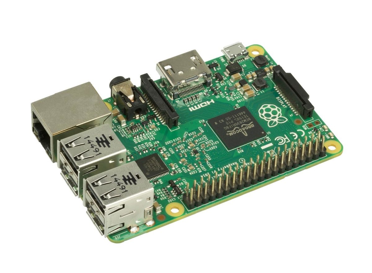
In this post, I’ll show you how to blink an LED on Raspberry Pi 3 Model B+. This project shows you how to use the Raspberry Pi’s GPIO (General Purpose Input Output) pins as an output to manipulate an external device (in this case the LED).
Requirements
Here are the requirements:
- Make an LED blink on Raspberry Pi 3 Model B+.
You Will Need
The following components are used in this project. You will need:
- Canakit Raspberry Pi 3 B+ (Pre-loaded with NOOBS)
- Solderless breadboard
- 5mm Red LED
- Assortment of 1/4 Watt Resistors
- Male to female jumper wire
Directions
Set up the Raspberry Pi
Set up the Raspberry Pi as explained in this video:
Explore the Raspberry Pi (Optional)
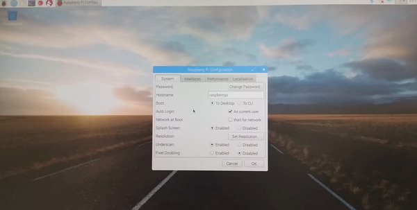
From the Raspberry Pi desktop, click the Pi logo, and go to Preferences -> Raspberry Pi Configuration. Make sure your settings look like the image below and reboot (we’ll make use of these settings in future posts):
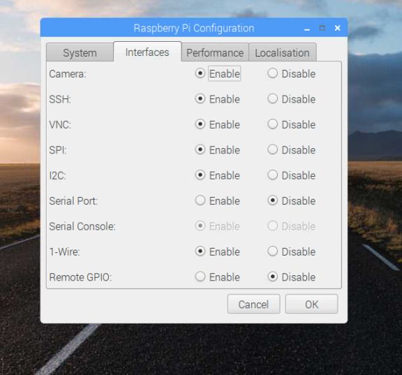
- Camera: Enables us to use the official Raspberry Pi camera module
- SSH (Secure Shell): A “cryptographic network protocol for operating network services securely over an unsecured network.” Enabling this enables us to access the Raspberry Pi remotely.
- VNC (Virtual Network Computing): “A graphical desktop-sharing system that uses the Remote Frame Buffer protocol (RFB) to remotely control another computer.” Also enables us to access the Raspberry Pi remotely from another computer.
- SPI (Serial Peripheral Interface): Serial communication interface good for communication over short distances. SPI pertains to functions on the GPIO pins of the Raspberry Pi.
- I2C (Inter-Integrated Circuit): A master-slave communication protocol. Also pertains to functions on the GPIO pins of the Raspberry Pi.
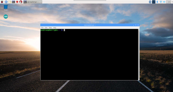
Before we dive into the LED project, let’s have a look at the Raspberry Pi terminal.
The terminal is a way to communicate with your computer. Back in the 1980s and early 1990s when I first started using computers, the command-line interface of the terminal was the main way to send commands to your computer.
Back in those days computers did not have the processing power they have now. If you were born in the 1990s or later, you probably have only interacted with your computer via a graphical user interface. I like to use the command-line interface for robotics projects because it is more efficient, and you can tell the computer exactly what to do.
To open the terminal, click the Raspberry Pi logo in the upper left of the Raspberry Pi desktop and go to Accessories -> Terminal.
That black window you are looking at is the terminal. Typing ls will display all the files and folder in that directory. Blue items are directories. Green text shows our username (i.e “pi”).
To change to a directory, you use the cd Directory Name command. For example cd Documents, gets you to the Documents directory.
Determine What Resistor to Use
Find out what the forward voltage is of your 5mm LED. Forward voltage is the minimum voltage required in order for the LED to light up. The forward voltage for my red LED is 1.8-2.2V.
Raspberry Pi is powered by 5V micro USB (2.5A). Each GPIO (General Purpose Input Output) pin supplies 3.3V (our source voltage) and can provide 16mA of current. Since 3.3V > 2.2V, we know that Raspberry Pi has enough voltage to power the LED.
Forward voltage is also the amount of voltage lost when a current runs through the LED. Consider it the “voltage drop” across the LED. To understand the basics of this concept, check out this 3D animation.
Find out what the maximum forward current of the 5mm LED is. Maximum forward current is the maximum current the LED can handle before it is at risk of getting damaged. The maximum forward current of my LED is 20mA (0.02A), which I obtained from the LED’s datasheet.
Now, we calculate the value of the resistor we need using Ohm’s Law (V = I * R):
- Source voltage in volts = 3.3V
- Forward voltage of LED = 1.8V
- Maximum current of LED = 20mA = 0.02A
Resistor in ohms = ((Source voltage in volts) - (Forward voltage of LED in volts)) / (Maximum current in amps) = (Voltage leftover after the LED drops some of it) / (Maximum current)
Resistor in ohms = (3.3 - 1.8) / 0.02 = 75 ohms
So, we need at least a 75 ohm resistor. I’ll chose 330 ohms. The higher the resistor value you use, the dimmer the LED.
What is the current (represented as the capital letter ‘I’) in this case?
(3.3V - 1.8V) = I * 330
I = 4.5mA (which is well under the 20mA max current)
Now, we need to calculate how much power the resistor the LED can dissipate before it fails. We use this equation (P = VI):
Power in watts = Voltage in volts * Current in amps
Power in watts = (3.3 - 1.8) * 0.02A = 0.03 watts
Our resistor is rated at 0.25 watts, so we have more than enough cushion. We are good to go!
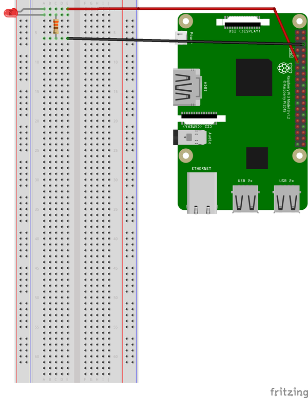
Wire the LED to the Breadboard
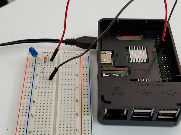
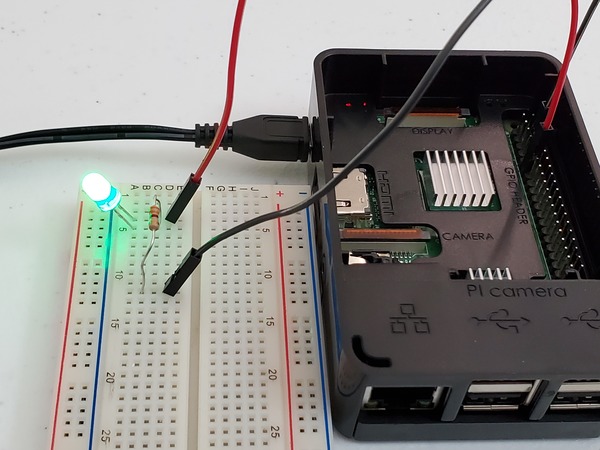
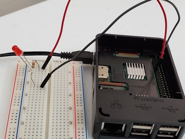
Here is the diagram to use to wire (using male to female jumper wire) the 330 ohm resistor and 5mm LED to the Raspberry Pi. That kink in one of the LEDs represents the long leg of the LED:
Blink the LED
Now we need to write a program in Python to blink the LED.
I have a folder in my Home Directory named robot. I get to this directory by opening up a terminal window in Raspberry Pi and typing:
cd robot
Now, we open up the Nano text editor to enable us to write the Python program. We name it led_blink.py. Here is the terminal command:
nano led_blink.py
We type in this python code:
import gpiozero  # The GPIO library for Raspberry Pi
import time  # Enables Python to manage timing

led = gpiozero.LED(17) # Reference GPIO17

while True:
  led.on() # Turn the LED on
  time.sleep(1)
  led.off() # Turn the LED off
  time.sleep(1)  # Pause for 1 second
We then press CTRL-X, then Y, then press Enter to save the program and return to the terminal.
To run the program, we type:
python3 led_blink.py
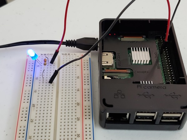
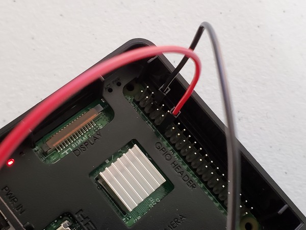
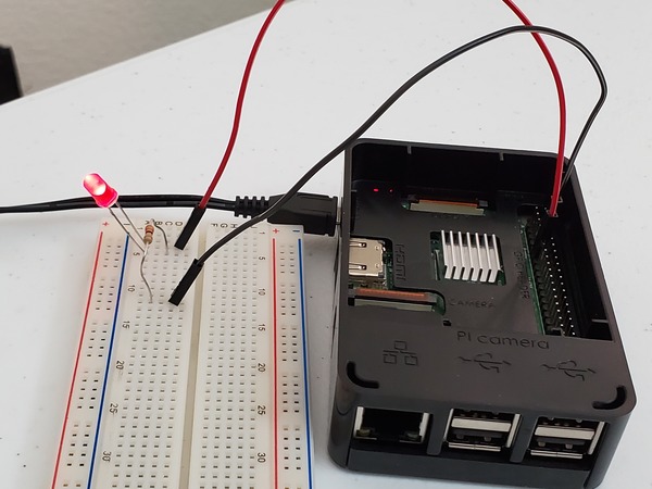
Your LED should be blinking. If it doesn’t blink, try connecting the red positive lead to another GPIO pin on the Raspberry Pi.
To stop the program, you press CTRL-C.
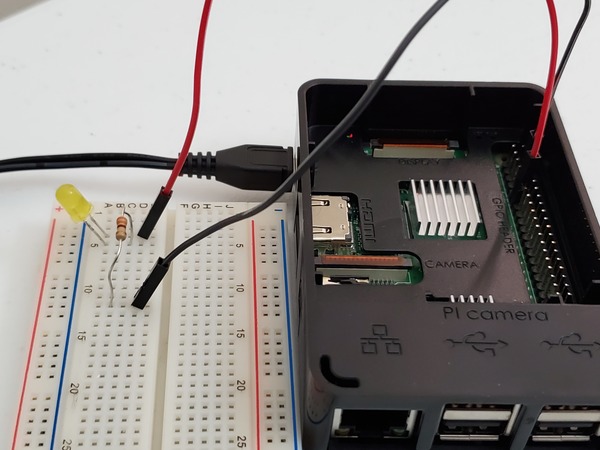
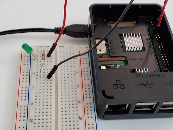
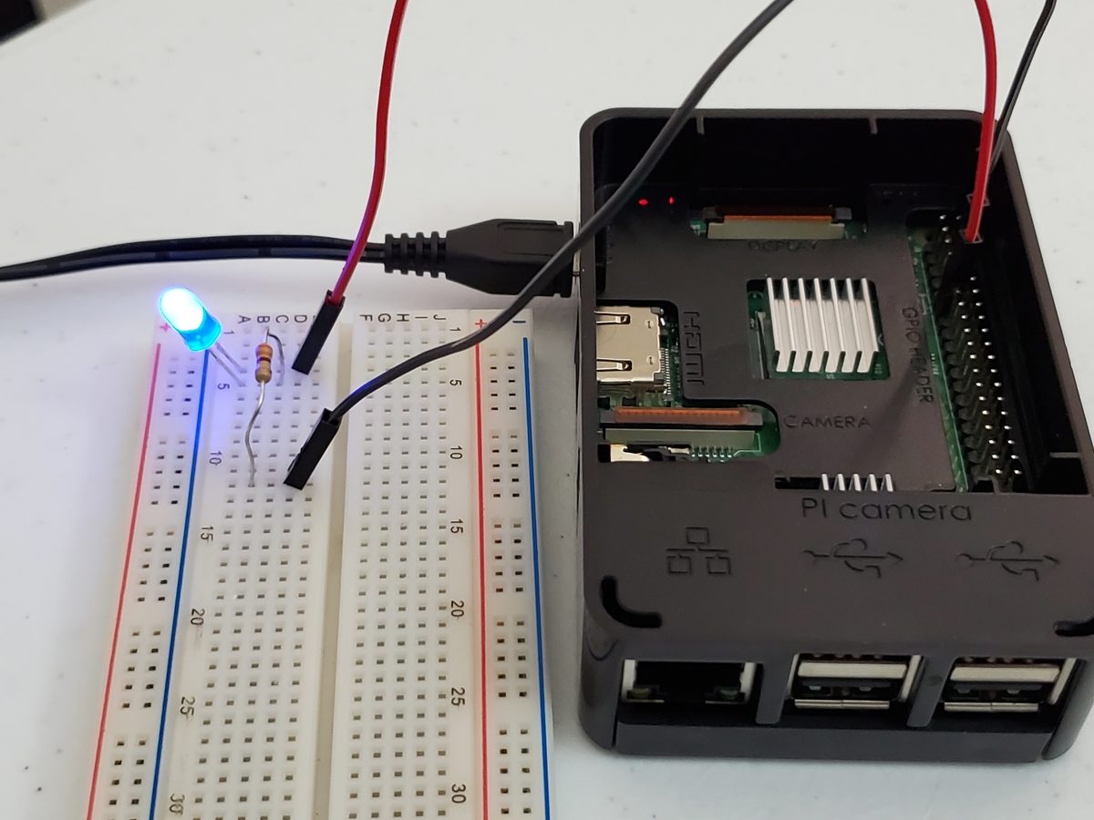
You can also try different color LEDs, as shown below.