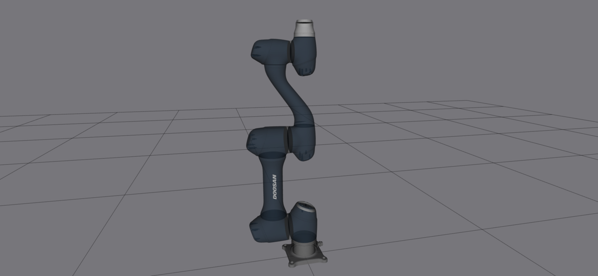
In this tutorial, I will guide you through the process of creating a launch file for a robotic arm URDF file.
Launch files in ROS 2 are powerful tools that allow you to start multiple nodes and set parameters with a single command, simplifying the process of managing your robot’s complex systems.
Prerequisites
- You understand what a joint and link are.
- You have created a ROS 2 workspace.
- You know what a ROS 2 package is.
- You have a simulated robotic arm that you want to launch with a single command.
All my code for this project is located here on GitHub.
Directions
Open a terminal window.
Move to your robotic arm directory (e.g. mycobot_ros2).
cd ~/ros2_ws/src/mycobot_ros2/mycobot_description/mkdir launchcd launchgedit mycobot_280_arduino_view_description.launch.pyAdd this code.
# Author: Addison Sears-Collins
# Date: March 26, 2024
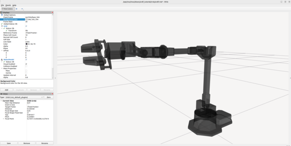
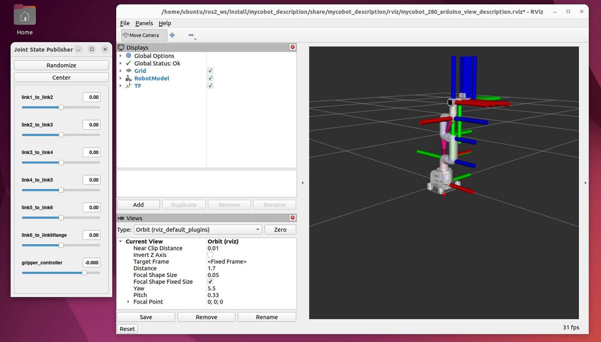
# Description: Display the robotic arm with RViz
from launch import LaunchDescription
from launch.actions import DeclareLaunchArgument
from launch.conditions import IfCondition, UnlessCondition
from launch.substitutions import Command, LaunchConfiguration, PathJoinSubstitution
from launch_ros.actions import Node
from launch_ros.parameter_descriptions import ParameterValue
from launch_ros.substitutions import FindPackageShare
def generate_launch_description():
# Define filenames
urdf_package = 'mycobot_description'
urdf_filename = 'mycobot_280_urdf.xacro'
rviz_config_filename = 'mycobot_280_arduino_view_description.rviz'
# Set paths to important files
pkg_share_description = FindPackageShare(urdf_package)
default_urdf_model_path = PathJoinSubstitution([pkg_share_description, 'urdf', urdf_filename])
default_rviz_config_path = PathJoinSubstitution([pkg_share_description, 'rviz', rviz_config_filename])
# Launch configuration variables specific to simulation
jsp_gui = LaunchConfiguration('jsp_gui')
rviz_config_file = LaunchConfiguration('rviz_config_file')
urdf_model = LaunchConfiguration('urdf_model')
use_rviz = LaunchConfiguration('use_rviz')
use_sim_time = LaunchConfiguration('use_sim_time')
# Declare the launch arguments
declare_jsp_gui_cmd = DeclareLaunchArgument(
name='jsp_gui',
default_value='true',
choices=['true', 'false'],
description='Flag to enable joint_state_publisher_gui')
declare_rviz_config_file_cmd = DeclareLaunchArgument(
name='rviz_config_file',
default_value=default_rviz_config_path,
description='Full path to the RVIZ config file to use')
declare_urdf_model_path_cmd = DeclareLaunchArgument(
name='urdf_model',
default_value=default_urdf_model_path,
description='Absolute path to robot urdf file')
declare_use_rviz_cmd = DeclareLaunchArgument(
name='use_rviz',
default_value='true',
description='Whether to start RVIZ')
declare_use_sim_time_cmd = DeclareLaunchArgument(
name='use_sim_time',
default_value='false',
description='Use simulation (Gazebo) clock if true')
# Specify the actions
# Publish the joint state values for the non-fixed joints in the URDF file.
start_joint_state_publisher_cmd = Node(
package='joint_state_publisher',
executable='joint_state_publisher',
name='joint_state_publisher',
condition=UnlessCondition(jsp_gui))
# Depending on gui parameter, either launch joint_state_publisher or joint_state_publisher_gui
start_joint_state_publisher_gui_cmd = Node(
package='joint_state_publisher_gui',
executable='joint_state_publisher_gui',
name='joint_state_publisher_gui',
condition=IfCondition(jsp_gui))
# Subscribe to the joint states of the robot, and publish the 3D pose of each link.
robot_description_content = ParameterValue(Command(['xacro ', urdf_model]), value_type=str)
start_robot_state_publisher_cmd = Node(
package='robot_state_publisher',
executable='robot_state_publisher',
name='robot_state_publisher',
output='screen',
parameters=[{
'use_sim_time': use_sim_time,
'robot_description': robot_description_content}])
# Launch RViz
start_rviz_cmd = Node(
condition=IfCondition(use_rviz),
package='rviz2',
executable='rviz2',
name='rviz2',
output='screen',
arguments=['-d', rviz_config_file],
parameters=[{
'use_sim_time': use_sim_time}])
# Create the launch description and populate
ld = LaunchDescription()
# Declare the launch options
ld.add_action(declare_jsp_gui_cmd)
ld.add_action(declare_rviz_config_file_cmd)
ld.add_action(declare_urdf_model_path_cmd)
ld.add_action(declare_use_rviz_cmd)
ld.add_action(declare_use_sim_time_cmd)
# Add any actions
ld.add_action(start_joint_state_publisher_cmd)
ld.add_action(start_joint_state_publisher_gui_cmd)
ld.add_action(start_robot_state_publisher_cmd)
ld.add_action(start_rviz_cmd)
return ld
Now add the RViz configuration file.
cd ..
mkdir rviz
cd rviz
gedit mycobot_280_arduino_view_description.rviz
Add this code.
Panels:
  - Class: rviz_common/Displays
    Name: Displays
  - Class: rviz_common/Views
    Name: Views
Visualization Manager:
  Displays:
    - Class: rviz_default_plugins/Grid
      Name: Grid
      Value: true
    - Alpha: 0.8
      Class: rviz_default_plugins/RobotModel
      Description Topic:
        Value: /robot_description
      Name: RobotModel
      Value: true
    - Class: rviz_default_plugins/TF
      Name: TF
      Value: true
  Global Options:
    Fixed Frame: base_link
  Tools:
    - Class: rviz_default_plugins/MoveCamera
  Value: true
  Views:
    Current:
      Class: rviz_default_plugins/Orbit
      Distance: 1.7
      Name: Current View
      Pitch: 0.33
      Value: Orbit (rviz)
      Yaw: 5.5
Window Geometry:
  Height: 800
  Width: 1200
Edit CMakeLists.txt.
cd ..
gedit CMakeLists.txt
cmake_minimum_required(VERSION 3.8)
project(mycobot_description)

# Check if the compiler being used is GNU's C++ compiler (g++) or Clang.
# Add compiler flags for all targets that will be defined later in the
# CMakeLists file. These flags enable extra warnings to help catch
# potential issues in the code.
# Add options to the compilation process
if(CMAKE_COMPILER_IS_GNUCXX OR CMAKE_CXX_COMPILER_ID MATCHES "Clang")
  add_compile_options(-Wall -Wextra -Wpedantic)
endif()

# Locate and configure packages required by the project.
find_package(ament_cmake REQUIRED)

# Copy necessary files to designated locations in the project
install (
  DIRECTORY launch meshes rviz urdf
  DESTINATION share/${PROJECT_NAME}
)

# Automates the process of setting up linting for the package, which
# is the process of running tools that analyze the code for potential
# errors, style issues, and other discrepancies that do not adhere to
# specified coding standards or best practices.
if(BUILD_TESTING)
  find_package(ament_lint_auto REQUIRED)
  # the following line skips the linter which checks for copyrights
  # comment the line when a copyright and license is added to all source files
  set(ament_cmake_copyright_FOUND TRUE)
  # the following line skips cpplint (only works in a git repo)
  # comment the line when this package is in a git repo and when
  # a copyright and license is added to all source files
  set(ament_cmake_cpplint_FOUND TRUE)
  ament_lint_auto_find_test_dependencies()
endif()

ament_package()
Build your workspace.
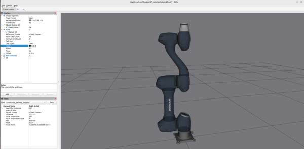
cd ~/ros2_ws/colcon buildsource ~/.bashrcNow launch your launch file:
ros2 launch mycobot_description mycobot_280_arduino_view_description.launch.py