In this tutorial, we will build a self-balancing robot from scratch, step-by-step. The “brain” of the robot will be based on Arduino, a popular microcontroller (i.e. mini computer) used for robotics projects.
Real-World Applications
Perhaps the most famous real-world example of a self-balancing robot is the Segway, a two-wheeled motorized personal vehicle.
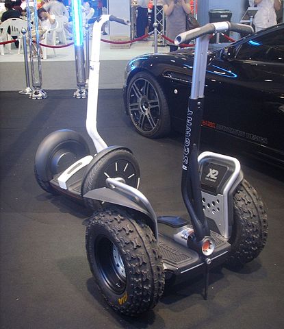
We will build an early prototype of the product you see above. Let’s get started!
Table of Contents
- Real-World Applications
- Prerequisites
- Requirements
- You Will Need
- -DC Motor With Encoder
- -Microcontroller Board
- -Motor Driver Chip
- -Inertial Measurement Unit (IMU)
- -Power Supply
- -Bluetooth Interface (Optional)
- Assembly Directions
- Test the Motors
- Test the Built-in Hall Encoder
- Test the Built-in Internal Timer
- Test the MPU6050 Sensor
- Calculate the Tilt Angle and Angular Velocity
- Calculate the Tilt Angle and Angular Velocity Using a Kalman Filter
- Use Control Theory to Keep the Robot Upright
- -How a PID Controller Works
- -Write a Controller to Keep Your Robot Upright
- Challenge Exercise: Connect the Arduino (via the pins in the Balance Shield) to a Bluetooth Receiver
Prerequisites
- You have the Arduino IDE (Integrated Development Environment) installed on your PC (Windows, MacOS, or Linux) and know how to upload a new program to an Arduino.
Requirements
Here are the requirements:
- Build a two-wheeled robot that is able to self-balance.
- Use control theory and sensor fusion techniques (Feedback control system, PID, Kalman Filters, etc.) to keep the robot upright.
You Will Need
This section is the complete list of components you will need for this project.
- Self-balancing Robot Car Kit (I’m using the one made by keyestudio, but if that kit isn’t available, there are a number of self-balancing robot car kits on places like Amazon and eBay). A couple of other good brands are Osoyoo and Elegoo.
- Electrical Components
- 1 UNO R3 Board and 50 cm Cable
- 2 GM37-520 DC Gear Motor 12V
- 1 Keyestudio Balance Shield V3
- 1 Bluetooth XBee HC-06
- 1 18650 3-Cell AA Battery Case
- Mechanical Components
- 2 Motor Iron Holder
- 1 Acrylic Plate Pack of 2 Pieces
- 2 6pin 30cm Connector Wire
- 2 Wheels
- 1 Phillips Screwdriver 3*40mm
- 1 L Type M2 Nickel Plating Inner Hex Wrench
- 1 Black Winding Tube 60cm
- 4 Copper Pillar M3*10mm
- 2 Copper Hex Couplers
- 4 Copper Pillar M3*45mm
- 2 Flat Head Screw M3*12mm
- 12 Nickel Plating Nut M3
- 2 Black M4*6 Screws
- 4 Flat Head Screw M3*8mm
- 6 Round Head Screw M3*6mm
- 10 Round Head Screw M3*8mm
- 10 Round Head Screw M3*12mm
- Electrical Components
The self-balancing car kits come and go. So while the keyestudio kit I’m using is available right now (on both eBay and Amazon), it might not always be available. If that is the case, you can buy another similar-looking kit or buy all the parts separately.
Here are the key electrical components you want to make sure to have:
DC Motor With Encoder
I’m using GM37-520 DC gear motors (with built-in encoder) that have the following specifications:
- Operating voltage: DC12V
- Reduction ratio: 1:30
- No-load current <= 100mA
- No-load speed: 247rpm
- Rated torque: 1.4 Kg.cm
- Rated torque: 137.4mN.m
- Rated speed: 160 rpm
- Rated current <= 0.45A
- Stalled torque: 5.5 Kg.cm
- Stop current: 2.4A
- Reducer length: 22mm
You want to make sure your motors have encoders to help you measure motor speed.
Another motor that works well is the JGB37-520B 12V DC Geared Motor 12rpm with Encoder Disk.
Microcontroller Board
I’m using the Arduino Uno Rev3. At present, it is the most used microcontroller board in the whole Arduino family. Without it, you will be unable to program the robot.
Motor Driver Chip
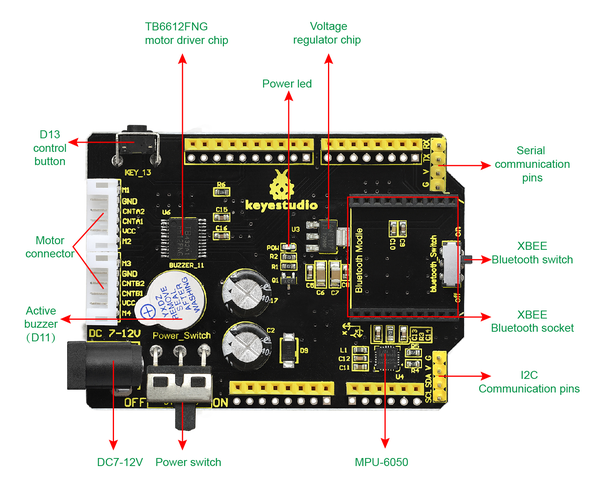
You want a dual H-bridge motor driver chip like the TB6612FNG. This electronic component receives signals from the Arduino microcontroller board and then relays those signals to each motor.
In the kit that I bought, the TB6612FNG is already built-in to the Keyestudio Balance Shield V3.
Inertial Measurement Unit (IMU)
You need to have an IMU to measure position and orientation of the car. Without the IMU, the robot will not be able to self-balance.
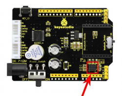
The IMU that I’m using is the MPU-6050 sensor. Just like the TB6612FNG motor driver chip, the MPU-6050 is already built-in to the Keyestudio Balance Shield V3. This balance shield has an operating voltage of 7-12V.
Power Supply
Your 12V DC motors need power. I’m using three 18650 3.7V (5000mAh) Lithium-ion rechargeable batteries (i.e. 11.1V in total).
You will put these batteries inside an 18650 3-cell AA battery case with 15cm lead + plug.
In my setup, I will plug the 3-cell battery case into the DC 7-12V port of the Keyestudio Balance Shield V3.
Bluetooth Interface (Optional)
I’m not using Bluetooth in this tutorial. However, if you want to tinker around with Bluetooth so that you can control the robot with your smartphone, I recommend buying a Bluetooth module like the HC-05 or HC-06.
Assembly Directions
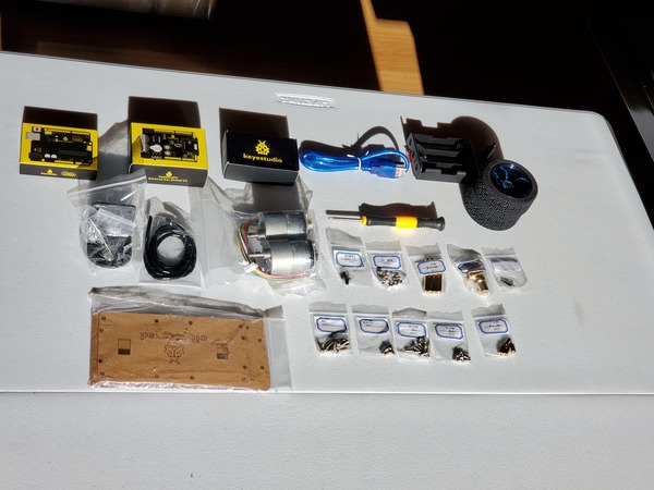
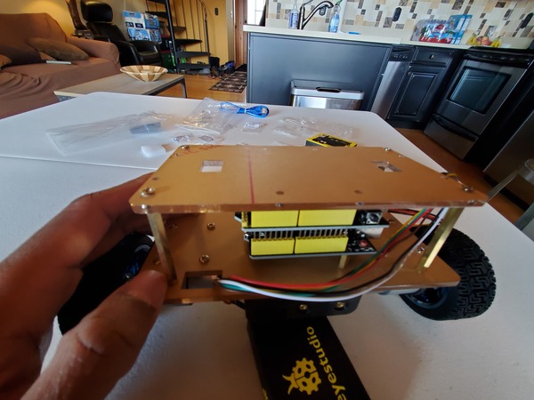
Lay out all the project components on a table, and make sure you have everything I listed in the parts list above.
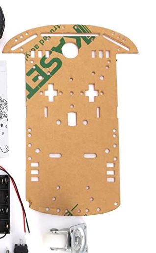
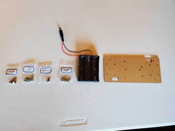
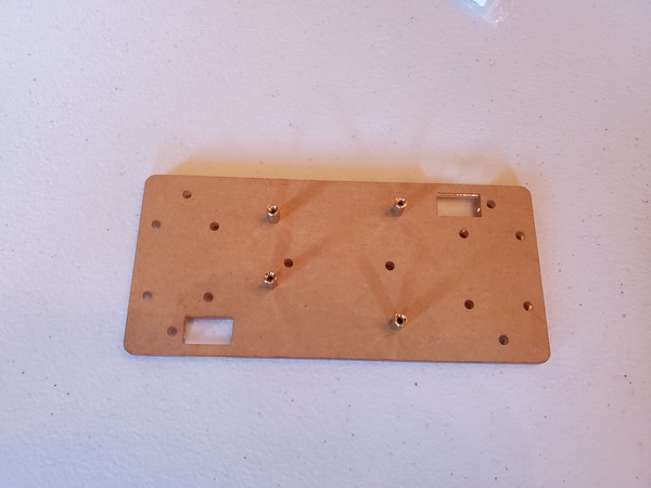
Grab the Bottom Acrylic Plate, the 4 Copper Pillars M3*10mm, battery holder, and the 4 M3*8mm Screws.
Screw the copper pillars into the bottom acrylic plate.
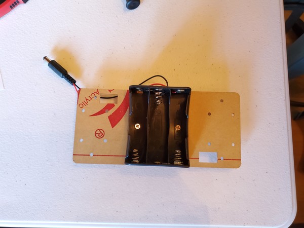
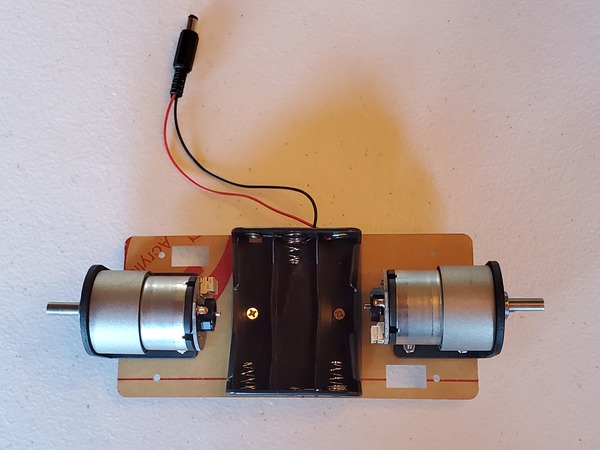
Grab 2 M3*12mm Flat Head Screws and 2 Nickel Plating Nuts M3. Mount the battery holder.
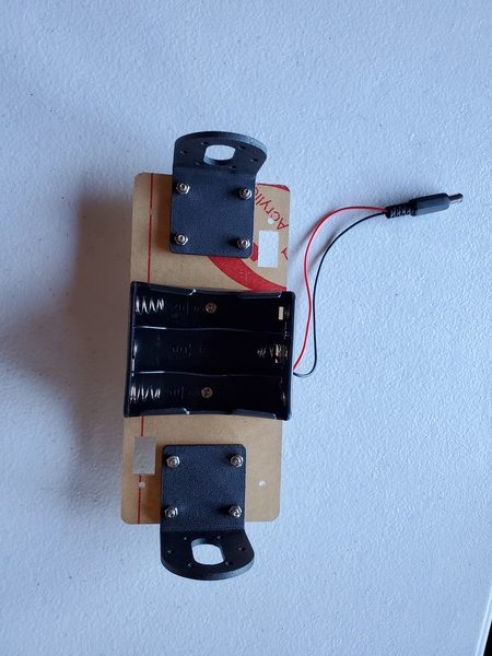
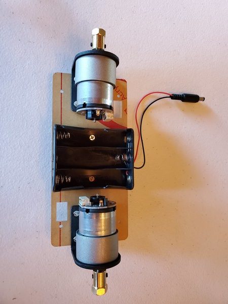
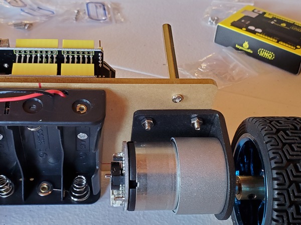
Grab the 2 Motor Iron Holders, 8 M3*12mm Round Head Screws, and 8 Nickel Plating Nuts M3.
Secure the 2 Motor Iron Holders to the Bottom Acrylic Plate.
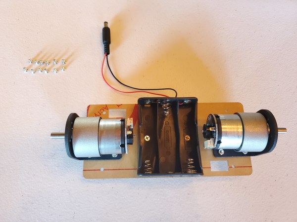
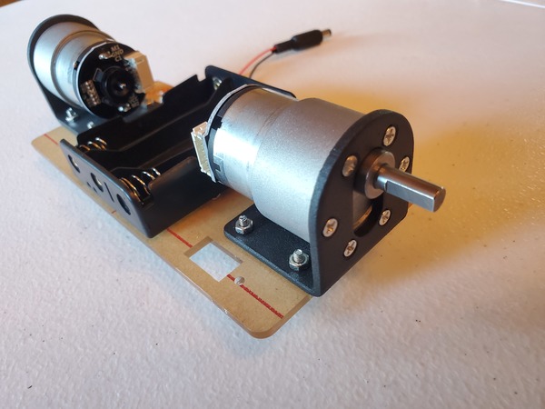
Grab both motors and mount them into the Motor Iron Holders.
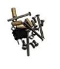
You have a bag with 12 small screws. Take those screws and secure the motor into the Motor Iron Holder.
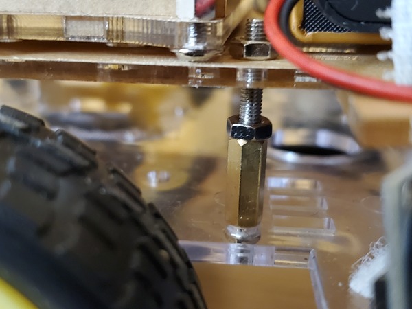
Grab both of the Copper Hex Couplers.
Grab the Hex Wrench.
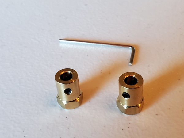
Loosen the screws on both sides of each Hex Wrench. Don’t pull them all the way out though.
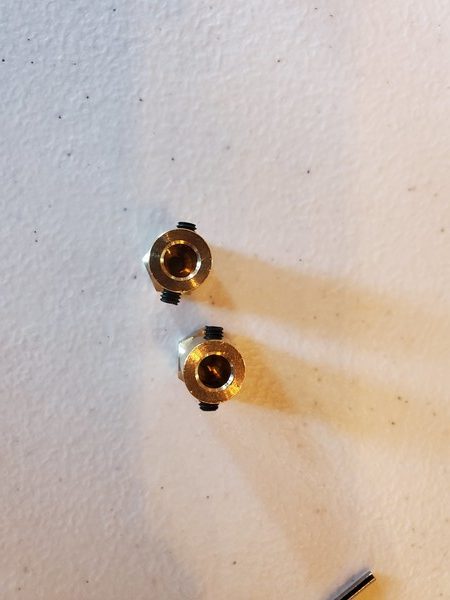
Snap the Copper Hex Couplers over the motors. Then tighten the screws using the wrench to secure the Hex Couplers on to the motors.
Grab the two wheels.
Grab 2 Black M4*6 Screws.
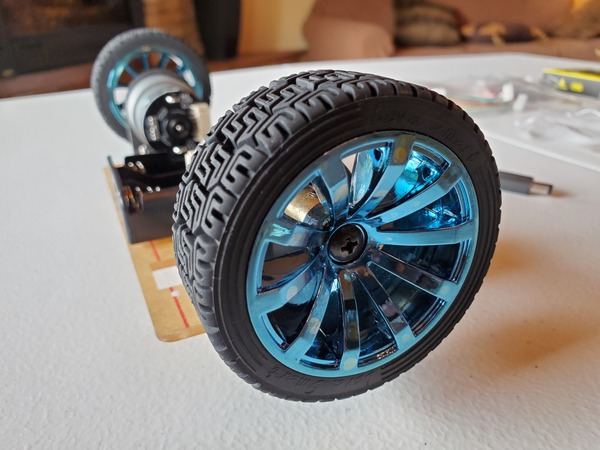
Put the wheels over the Hex Couplers, and use the 2 Black M4*6 Screws to secure the wheels into place.
Grab the UNO R3 Board and 3 Round Head Screw M3*6mm (yes 3, not 4, even though there are four holes).
Secure the UNO to the copper pillars using the screws. I like to use needle-nose pliers to hold the pillar in place while I tighten the screw.
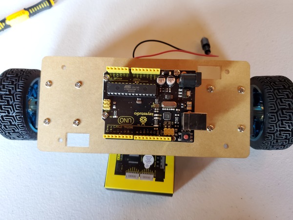
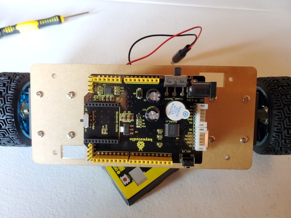
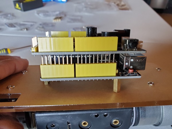
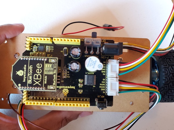
Grab the Balance Shield.
Stack it on top of the UNO. The spikes underneath the Balance Shield need to sink into the holes of the UNO.
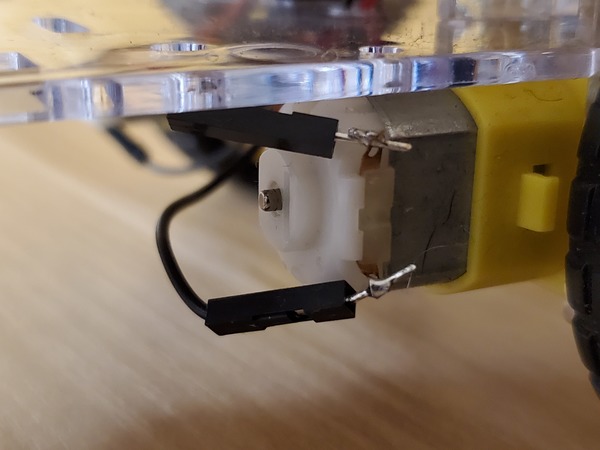
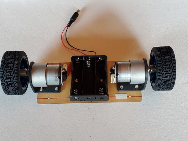
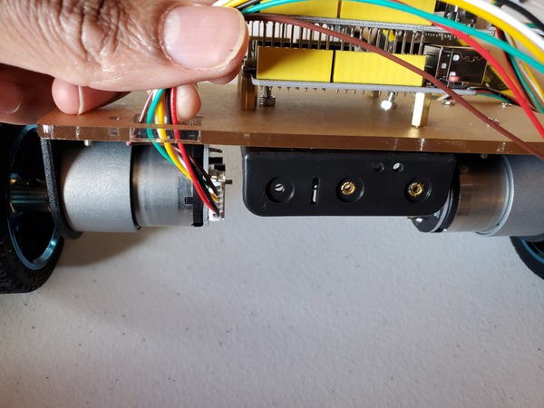
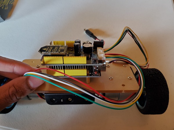
Grab both 6pin 30cm Connector Wires.
Use the Connector Wires to connect the motors to the closest slot on the Balance Shield. Guide the Connector Wires through the holes of the Acrylic Board then plug them in.
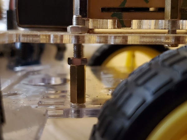
Grab 4 M3*45mm copper pillars and 4 M3*8mm round head screws. Screw these in.
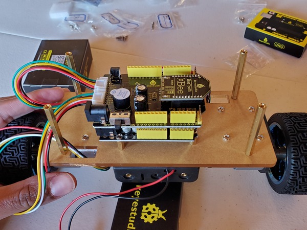
Grab the Acrylic Top Plate and 4 M3*8MM flat-head screws. Screw in the plate.
Grab the 2 black winding tubes and use them to wrap the Wire Connectors.
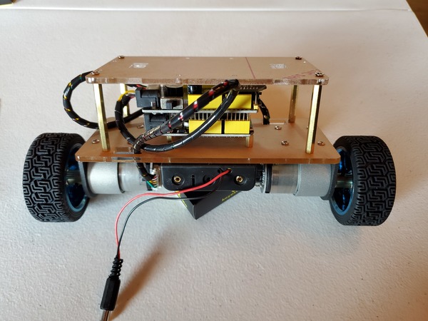
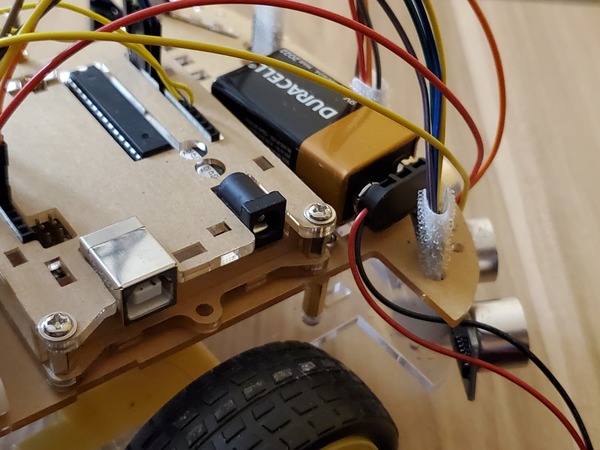
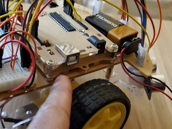
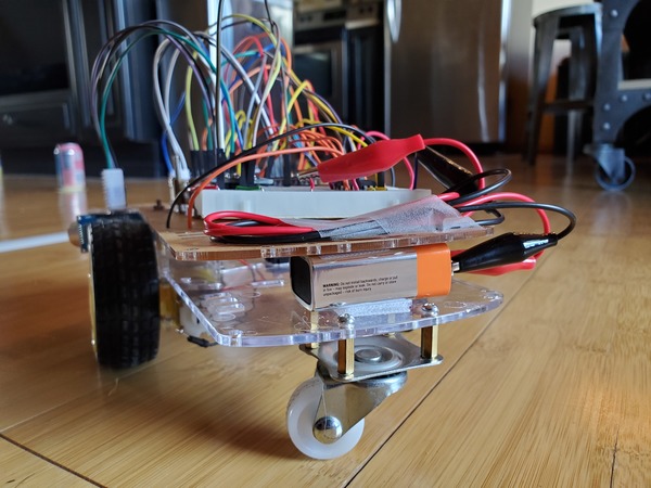
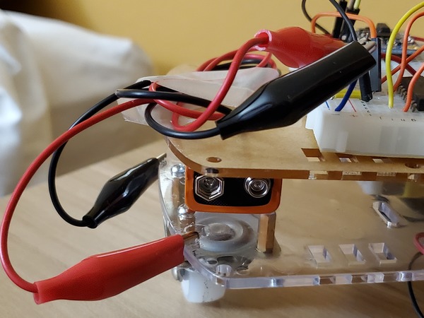
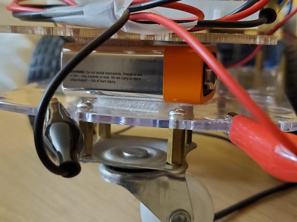
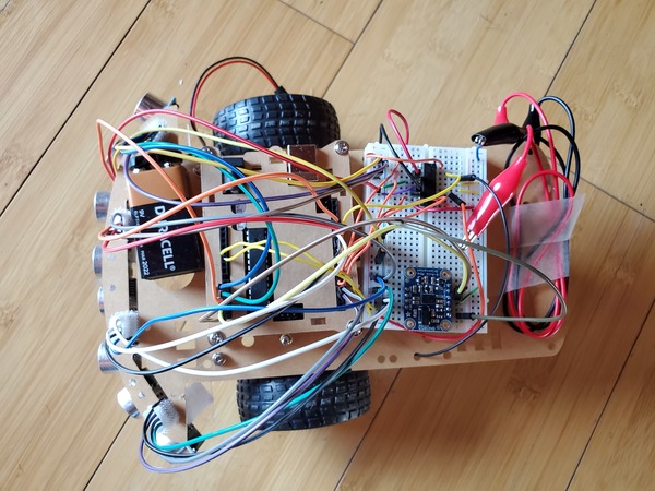
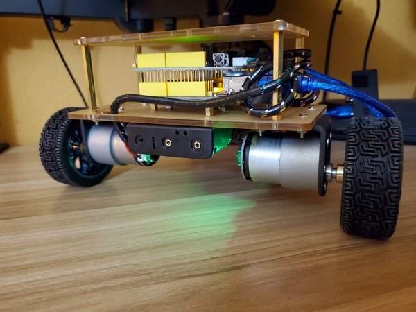
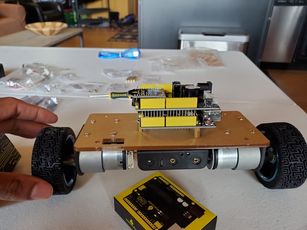
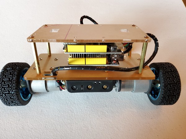
That’s it for the assembly. You should have a lot of extra screws and a couple nuts. That’s fine.
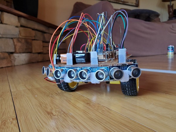
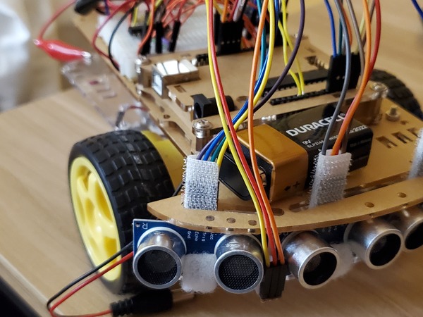
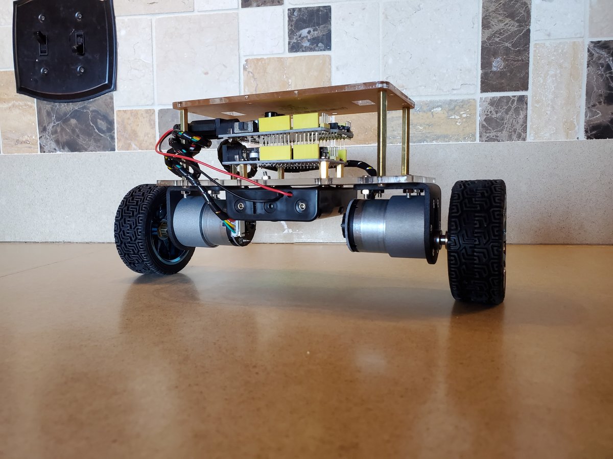
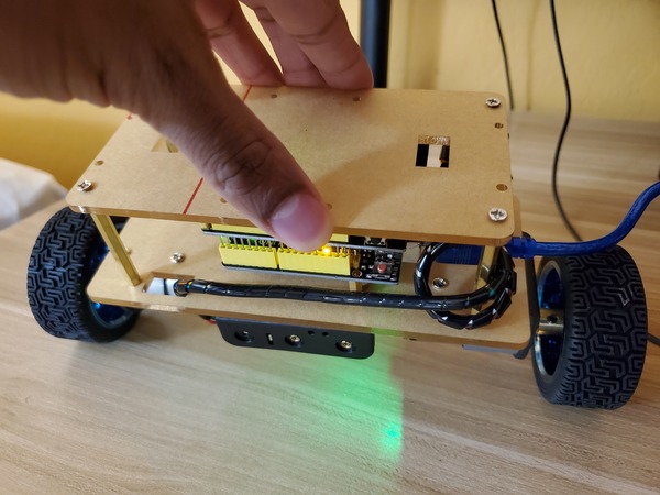
Here is how the robot should look:
Now, at this stage, you should install the Arduino IDE on your Windows, Linux, or Mac computer.
Test the Motors
Let’s test the motors to make sure they work.
Plug the Arduino into the USB port of your computer using the USB cord.
Make sure your robot is upside down with the Acrylic plate on the bottom and the wheels facing upwards.
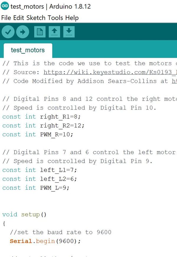
Copy and paste the code below into a new Arduino sketch.
// This is the code we use to test the motors of the keyesstudio Self-balancing car kit.
// Source: https://wiki.keyestudio.com/Ks0193_keyestudio_Self-balancing_Car
// Code Modified by Addison Sears-Collins at https://automaticaddison.com

// Digital Pins 8 and 12 control the right motor's direction.
// Speed is controlled by Digital Pin 10.
const int right_R1=8;
const int right_R2=12;
const int PWM_R=10;

// Digital Pins 7 and 6 control the left motor's direction.
// Speed is controlled by Digital Pin 9.
const int left_L1=7;
const int left_L2=6;
const int PWM_L=9;


void setup()
{
  //set the baud rate to 9600
  Serial.begin(9600);

  // Set all the pins to OUTPUT
  // The motors' speed and direction is controlled by
  // the output of these pins
  pinMode(right_R1,OUTPUT);
  pinMode(right_R2,OUTPUT);
  pinMode(PWM_R,OUTPUT);
  pinMode(left_L1,OUTPUT);
  pinMode(left_L2,OUTPUT);
  pinMode(PWM_L,OUTPUT);
}

void loop()
{
  // Go forward for 3 seconds
  digitalWrite(right_R1,HIGH);
  digitalWrite(right_R2,LOW);
  digitalWrite(left_L1,LOW);
  digitalWrite(left_L2,HIGH);
  analogWrite(PWM_R,100);   // write into PWM value 0~255(speed)
  analogWrite(PWM_L,100);

  delay(3000);

   // Stop for 3 seconds
  digitalWrite(right_R1,HIGH);
  digitalWrite(right_R2,HIGH);
  digitalWrite(left_L1,HIGH);
  digitalWrite(left_L2,HIGH);
  analogWrite(PWM_R,100);   // write into PWM value 0~255(speed)
  analogWrite(PWM_L,100);

  delay(3000);

   // Reverse for 3 seconds
  digitalWrite(right_R1,LOW);
  digitalWrite(right_R2,HIGH);
  digitalWrite(left_L1,HIGH);
  digitalWrite(left_L2,LOW);
  analogWrite(PWM_R,100);   // write into PWM value 0~255(speed)
  analogWrite(PWM_L,100);   // The higher the PWM value, the faster the speed

  delay(3000);

  // Stop for 3 seconds
  // Notice that we can do all LOW or all HIGH to stop the robot.
  digitalWrite(right_R1,LOW);
  digitalWrite(right_R2,LOW);
  digitalWrite(left_L1,LOW);
  digitalWrite(left_L2,LOW);
  analogWrite(PWM_R,100);   // write into PWM value 0~255(speed)
  analogWrite(PWM_L,100);

  delay(3000);

}
Upload the sketch below into your Arduino. This sketch makes the motors go forward for three seconds, stop for three seconds, reverse for three seconds, and stop for three seconds. This code repeats over and over again.
To stop the sketch at any time, you can upload a blank sketch to the Arduino.
Test the Built-in Hall Encoder
In the previous section, we learned how to set the speed and direction of each motor of our robot. Now, let’s see how we can measure the actual speed of each motor. To do that, we will use the built-in hall encoder.
A motor uses magnets to convert incoming electricity into motion. A hall encoder is able to measure the motion of the motor by detecting variations in the magnetic field as the motor (and its magnets) spins around and around. The output from a hall encoder is a voltage, which is directly proportional to the strength of the magnetic field. The Arduino, in turn, measures the output voltage of the hall encoder.
We will define the speed of each motor as the number of pulses measured by the Hall encoder within 100ms. A pulse in this context is defined when the voltage read by the digital pin on the Arduino goes from HIGH (i.e. high voltage) to LOW (i.e. low voltage) or from LOW to HIGH.
Let’s open a new sketch in the Arduino IDE.
Go to File -> Save As, and save the new sketch as hall_encoder_test.
Upload the code to your board:
// This is the code we use to test the hall encoder on the Keyesstudio self-balancing car
// Speed is based on the number of pulses generated by the Hall encoder within 100ms
// Source: https://wiki.keyestudio.com/Ks0193_keyestudio_Self-balancing_Car
// Code Modified by Addison Sears-Collins at https://automaticaddison.com

// Digital Pins 8 and 12 control the right motor.
// Speed is controlled by Digital Pin 10.
const int right_R1=8;
const int right_R2=12;
const int PWM_R=10;

// Digital Pins 7 and 6 control the left motor's direction.
// Speed is controlled by Digital Pin 9.
const int left_L1=7;
const int left_L2=6;
const int PWM_L=9;

const int PinA_left = 1;    // set the left motor’s pulse pin to Digital Pin 1
const int PinA_right = 4;   // set the right motor’s pulse pin to Digital Pin 4

int times = 0;    // Time
int newtime = 0;  // New Time
int d_time = 100; // Time Interval set to 100ms

int valA = 0; // Number of pulses for left motor
int flagA = 0;

int valB = 0; // Number of pulses for right motor
int flagB = 0;

void setup() {

  //set the baud rate to 9600
  Serial.begin(9600);

  // Set all the pins to OUTPUT
  // The motors' speed and direction is controlled by
  // the output of these pins
  pinMode(right_R1,OUTPUT);
  pinMode(right_R2,OUTPUT);
  pinMode(PWM_R,OUTPUT);
  pinMode(left_L1,OUTPUT);
  pinMode(left_L2,OUTPUT);
  pinMode(PWM_L,OUTPUT);

  // The pulse pins are set to INPUT
  pinMode(PinA_right,INPUT);
  pinMode(PinA_left,INPUT);

}

void loop() {

  // Go forward
  digitalWrite(right_R1,HIGH);
  digitalWrite(right_R2,LOW);
  digitalWrite(left_L1,LOW);
  digitalWrite(left_L2,HIGH);

  // write into PWM value 0~255(speed)
  analogWrite(PWM_R,100);  // Right wheel
  analogWrite(PWM_L,200);  // Set Left wheel to be faster than the right wheel

  // Set newtime and times to Returns the number of
  // milliseconds passed since the Arduino board began
  // running the current program
  newtime = times = millis();

  while ((newtime-times) < d_time) {   // If we are less than 100ms, keep looping
    if(digitalRead(PinA_left) == HIGH && flagA == 0) { // If HIGH is detected
      valA++;      // valA plus 1
      flagA = 1;
    }
    if(digitalRead(PinA_left) == LOW && flagA == 1) {  // if LOW is detected
      valA++;     // valA plus 1
      flagA = 0;
    }
    if(digitalRead(PinA_right) == HIGH && flagB == 0) { // if HIGH is detected
      valB++;     // valB plus 1
      flagB = 1;
    }
    if(digitalRead(PinA_right) == LOW && flagB == 1) {  // if LOW is detected
      valB++;
      flagB = 0;
    }

    newtime = millis();        // Update the new time
  }

  // Print out the number of pulses in 100ms for the left motor
  Serial.println(String("Left Motor: ") + valA);

  // Print out the number of pulses in 100ms for the right motor
  // valA (left motor) should be greater than valB (right motor)
  Serial.println(String("Right Motor: ") + valB);

  valA = valB = 0; // Reset the values to 0

}
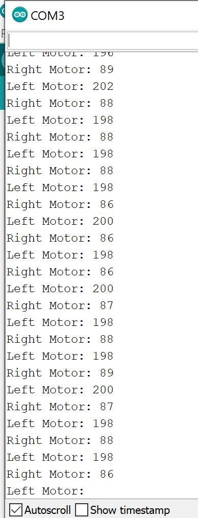
Click the magnifying glass in the upper right portion of the IDE.

Here is what you should see for your output. You see the number of pulses measured by the Hall encoder of each motor within 100ms.
When you’re ready, you can upload a blank sketch to your board to stop the wheels from turning.
Test the Built-in Internal Timer
In the previous code, to calculate the time elapsed between intervals of the loop, we based the calculation on the millis() Arduino function which measures the number of milliseconds elapsed since the program started.
The disadvantage of this method is that each loop is not precisely 100 milliseconds. We can get more precise timing by using our Arduino’s built-in timer, so let’s do that now.
Open up the Arduino IDE. If you have trouble opening it up, and you’re using Windows, go to C:\Users\<username>\AppData\Local\Arduino15 and delete everything other than the preferences.txt file.
Now install the MsTimer2 library by going to Sketch -> Include Library -> Manage Libraries.
Then type MsTimer2 in the search box and press Enter.
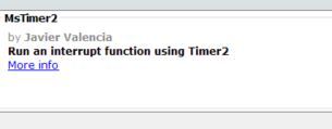
Click Install.
Then click OK once it has installed.
Now open up a new sketch in the Arduino IDE, and type the following code:
// This is the code to test the built-in internal timer in the Arduino
// Speed is based on the number of pulses generated by the Hall encoder within 100ms
// Source: https://wiki.keyestudio.com/Ks0193_keyestudio_Self-balancing_Car
// Code Modified by Addison Sears-Collins at https://automaticaddison.com

#include <MsTimer2.h>

// Digital Pins 8 and 12 control the right motor.
// Speed is controlled by Digital Pin 10.
const int right_R1=8;
const int right_R2=12;
const int PWM_R=10;

// Digital Pins 7 and 6 control the left motor's direction.
// Speed is controlled by Digital Pin 9.
const int left_L1=7;
const int left_L2=6;
const int PWM_L=9;

const int PinA_left = 1;    // set the left motor’s pulse pin to Digital Pin 1
const int PinA_right = 4;   // set the right motor’s pulse pin to Digital Pin 4

int times = 0;    // Time
int newtime = 0;  // New Time
int d_time = 100; // Time Interval set to 100ms

int valA = 0; // Number of pulses for left motor
int flagA = 0;

int valB = 0; // Number of pulses for right motor
int flagB = 0;

void setup() {

  //set the baud rate to 9600
  Serial.begin(9600);

  // Set all the pins to OUTPUT
  // The motors' speed and direction is controlled by
  // the output of these pins
  pinMode(right_R1,OUTPUT);
  pinMode(right_R2,OUTPUT);
  pinMode(PWM_R,OUTPUT);
  pinMode(left_L1,OUTPUT);
  pinMode(left_L2,OUTPUT);
  pinMode(PWM_L,OUTPUT);

  // The pulse pins are set to INPUT
  pinMode(PinA_right,INPUT);
  pinMode(PinA_left,INPUT);

  MsTimer2::set(100, inter); // trigger an interrupt every 100ms
  MsTimer2::start();    // start interrupt

}

void loop() {

  // Go forward
  digitalWrite(right_R1,HIGH);
  digitalWrite(right_R2,LOW);
  digitalWrite(left_L1,LOW);
  digitalWrite(left_L2,HIGH);

  // write into PWM value 0~255(speed)
  analogWrite(PWM_R,100);  // Right wheel
  analogWrite(PWM_L,200);  // Set Left wheel to be faster than the right wheel

  if(digitalRead(PinA_left) == HIGH && flagA == 0) { // If HIGH is detected
    valA++;      // valA plus 1
    flagA = 1;
  }
  if(digitalRead(PinA_left) == LOW && flagA == 1) {  // if LOW is detected
    valA++;     // valA plus 1
    flagA = 0;
  }
  if(digitalRead(PinA_right) == HIGH && flagB == 0) { // if HIGH is detected
    valB++;     // valB plus 1
    flagB = 1;
  }
  if(digitalRead(PinA_right) == LOW && flagB == 1) {  // if LOW is detected
    valB++;
    flagB = 0;
  }
}

//interrupt function
void inter() {
    sei();    //allow whole interrupts
    Serial.print("Left Motor = ");   //print out the pulse value on serial monitor
    Serial.println(valA);
    Serial.print("Right Motor: = ");
    Serial.println(valB);
    valA = valB = 0;
}
Save the file as internal_timer_test.ino.
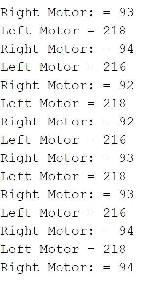
Upload the code to your board, and then click the magnifying glass in the upper right portion of the IDE.
Here is what you should see for your output:
Test the MPU6050 Sensor
We will now test the onboard MPU6050 sensor.
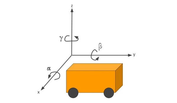
This sensor has a gyroscope to measure the angular velocity of the robot (relative to three different axes, x, y, and z) and an accelerometer to measure the linear acceleration of the robot (along three different axes, x, y, and z).
Our MPU6050’s gyroscope reports angular velocity in degrees/second. The range is +-250°/second.
Acceleration is reported in terms of G-forces (g). A single G-force (i.e. 1g) here on Earth is 9.8 m/s2.. The acceleration range is +-2g.
Open up a new sketch (test_mpu6050.ino) in Arduino, and type the following code. I recommend you type it one line at a time so that you read the comments slowly and understand what is going on:
Upload the code to your Arduino board, and save it as test_mpu6050.
/**
* Addison Sears-Collins
* June 11, 2020
* This code is used to test the MPU6050 IMU sensor chip that is built-in
* to the Keyestudio Balance Shield V3.
* This 3-axis gyroscope and the 3-axis accelerometer enable
* us to measure the angular velocity (in degrees/second)
* and the linear acceleration (in G-forces, g) of the
* self-balancing robot car.
*
**/
// Arduino's standard library for I2C communication
#include <Wire.h>
// Used to store accelerometer data
long accelX, accelY, accelZ;
float gForceX, gForceY, gForceZ;
// Used to store the gyroscope data
long gyroX, gyroY, gyroZ;
float rotX, rotY, rotZ; // Angular velocity around those axes
void setup() {
// Baud rate
Serial.begin(9600);
// Initialize I2C communication
Wire.begin();
setupMPU();
}
void loop() {
recordAccelRegisters();
recordGyroRegisters();
printData();
delay(100); // Delay of 100ms
}
/**
* Establish communication between Arduino and the MPU6050.
* Set up all registers we'll be using to read MPU6050 data
*/
void setupMPU(){
// REGISTER 0x6B/REGISTER 107:Power Management 1
// This is the I2C address of the MPU
//(b1101000/b1101001 for AC0 low/high datasheet Sec. 9.2)
// You can do a Google search to find the MPU6050 datasheet.
Wire.beginTransmission(0b1101000);
//Accessing the register 6B/107 - Power Management (Sec. 4.28)
Wire.write(0x6B);
//Setting SLEEP register to 0, using the internal 8 Mhz oscillator
Wire.write(0b00000000);
Wire.endTransmission();
// REGISTER 0x1b/REGISTER 27:Gyroscope Configuration
//I2C address of the MPU
Wire.beginTransmission(0b1101000);
//Accessing the register 1B - Gyroscope Configuration (Sec. 4.4)
Wire.write(0x1B);
// Setting the gyro to full scale +/- 250deg./s
// (250/360 * 60 = 41.67rpm)
// The highest can be converted to 2000deg./s (333.3 rpm), but
// gyro sensitivity will be reduced.
Wire.write(0x00000000);
Wire.endTransmission();
// REGISTER 0x1C/REGISTER 28:ACCELEROMETER CONFIGURATION
//I2C address of the MPU
Wire.beginTransmission(0b1101000);
// Accessing the register 1C - Acccelerometer Configuration (Sec. 4.5)
Wire.write(0x1C);
// Setting the accel to +/- 2g(if choose +/- 16g,
// the value would be 0b00011000)
Wire.write(0b00000000);
Wire.endTransmission();
}
void recordAccelRegisters() {
// REGISTER 0x3B~0x40/REGISTER 59~64
Wire.beginTransmission(0b1101000); //I2C address of the MPU
Wire.write(0x3B); //Starting register for Accelerometer Readings (see datasheet)
Wire.endTransmission();
Wire.requestFrom(0b1101000,6); //Request Accel Registers (3B - 40)
// Use left shift << and bit operations | Wire.read() read once 1bytes,and automatically read the data of the next address on the next call.
while(Wire.available() < 6); // Waiting for all the 6 bytes data to be sent from the slave machine (Must wait for all data to be stored in the buffer before reading)
accelX = Wire.read()<<8|Wire.read(); //Store first two bytes into accelX (Automatically stored as a defined long value)
accelY = Wire.read()<<8|Wire.read(); //Store middle two bytes into accelY
accelZ = Wire.read()<<8|Wire.read(); //Store last two bytes into accelZ
processAccelData();
}
// Divide the raw register reading to get a value that is meaningful for us
void processAccelData(){
gForceX = accelX / 16384.0; //float = long / float
gForceY = accelY / 16384.0;
gForceZ = accelZ / 16384.0;
}
void recordGyroRegisters() {
// REGISTER 0x43~0x48/REGISTER 67~72
Wire.beginTransmission(0b1101000); //I2C address of the MPU
Wire.write(0x43); //Starting register for Gyro Readings
Wire.endTransmission();
Wire.requestFrom(0b1101000,6); //Request Gyro Registers (43 ~ 48)
while(Wire.available() < 6);
gyroX = Wire.read()<<8|Wire.read(); //Store first two bytes into accelX
gyroY = Wire.read()<<8|Wire.read(); //Store middle two bytes into accelY
gyroZ = Wire.read()<<8|Wire.read(); //Store last two bytes into accelZ
processGyroData();
}
// The 131.0 comes from the MPU6050 datasheet. It helps us convert
// the raw data into a meaningful value.
void processGyroData() {
rotX = gyroX / 131.0;
rotY = gyroY / 131.0;
rotZ = gyroZ / 131.0;
}
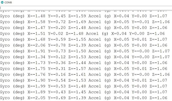
// Print out 3-axis gyroscope data and 3-axis accelerometer data
void printData() {
Serial.print("Gyro (deg)");
Serial.print(" X=");
Serial.print(rotX);
Serial.print(" Y=");
Serial.print(rotY);
Serial.print(" Z=");
Serial.print(rotZ);
Serial.print(" Accel (g)");
Serial.print(" X=");
Serial.print(gForceX);
Serial.print(" Y=");
Serial.print(gForceY);
Serial.print(" Z=");
Serial.println(gForceZ);
}
Now open the Serial Monitor by clicking on the magnifying glass in the upper-right part of the Integrated Development Environment (IDE).
Here is what you should see:
The gyroscope readings show the speed at which you rotate about a certain axis. For example, imagine your robot is on a table with the wheels touching the table. The z-axis goes straight into the table.
If you rotate the robot clockwise, the Gyro reading (i.e. angular velocity) for Z will decrease until you stop rotating it.
Likewise, if you rotate the robot counterclockwise, the Gyro reading for Z will increase until you stop rotating the board.
The accelerometer readings are a measure of the forces acting on it. So, for example, when the robot is stationary with wheels on the table, the only force acting on it is the force in the z-direction (through the table) due to gravity. The reading in this case is ~1g due to the force of gravity long the z direction.
If you were to move the robot along the x-direction (i.e. forward), the accelerometer would measure the acceleration along the x-direction in terms of Earth’s gravity (i.e. 1g).
Calculate the Tilt Angle and Angular Velocity
We now know how to use the gyroscope and accelerometer of the MPU6050, and we’ve verified the MPU6050 is working properly. Now, let’s use the MPU6050 to calculate the angle that the vehicle is tilting. I’ll call it the tilt angle. We will also measure the angular velocity of the self-balancing robot.
The first thing we need to do is install the MPU6050 library by Electronic Cats.
Go to Sketch -> Include Library -> Manage Libraries.
Then type “mpu6050” in the search box and press Enter.
Find the MPU6050 library by Electronic Cats.
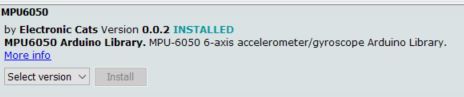
Click Install.
Then click OK once it has installed.
Now open up a new sketch in the Arduino IDE, and type the following code:
Save the file as calc_tilt_angle.
Upload the code to your board, and then click the magnifying glass in the upper right portion of the IDE.
/**
* Addison Sears-Collins
* June 13, 2020
* This code is uses the MPU6050 IMU sensor chip that
* is built-in to the Keyestudio Balance Shield V3 to
* calculate the angle that the vehicle is tilting.
**/

// MPU6050 library
#include <MPU6050.h>

// Arduino's standard library for I2C communication
#include <Wire.h>

// Create an MPU6050 object named mpu6050
MPU6050 mpu6050;

// Define three-axis acceleration and
// three-axis gyroscope variables
// 16-bit signed integer is the data type
int16_t ax, ay, az, gx, gy, gz;

// Variable that will hold the tilt angle
float Angle;

// Variable that will hold the angle velocity
int16_t Gyro_x;

void setup() {
  // Initialize I2C communication
  Wire.begin();

  // Set the baud rate
  Serial.begin(9600);

  // Don't do anything for 1500 milliseconds (1.5 seconds)
  delay(1500);

  // Initialize the MPU6050
  mpu6050.initialize();

  // Do nothing for 2 milliseconds
  delay(2);
}

void loop() {

  // I2C to get MPU6050 six-axis data  ax ay az gx gy gz
  mpu6050.getMotion6(&ax, &ay, &az, &gx, &gy, &gz);

  // Radial rotation angle calculation formula;
  // The negative sign indicates the direction.
  // Convert radians to degrees.
  Angle = -atan2(ay , az) * (180/ PI);

  // The x-axis angular velocity calculated by the gyroscope;
  // The negative sign indicates the direction. The 131 value comes
  // from the MPU6050 datasheet.
  Gyro_x = -gx / 131;

  // Print the tilt angle in degrees
  Serial.print("Angle = ");
  Serial.print(Angle);

  // Print the angular velocity in degrees per second
  Serial.print("   Gyro_x = ");
  Serial.println(Gyro_x);
}
Here is what you should see for your output:
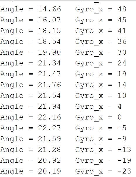
Notice that as you tilt the robot back and forth, the value for the tilt angle and angular velocity change accordingly.
Calculate the Tilt Angle and Angular Velocity Using a Kalman Filter
In the previous sketch, we calculated the tilt angle and angular velocity of the robot directly from the MPU6050. However, sensor measurements contain error and noise, so we can never be 100% certain if the tilt angle and angular velocity values are precisely what we see printed out to the Serial Monitor.
So how can we minimize this measurement error so that we can calculate readings of the tilt angle and angular velocity that are as accurate as possible? A time-tested technique is to use what is known as a Kalman Filter.
A Kalman Filter is an algorithm that uses a series of sensor measurements over time (rather than just a single estimate) to estimate the true state (i.e. the true tilt angle and angular velocity) of an object (i.e. the self-balancing robot). By taking into account both past and current measurements, a Kalman Filter can be used to help “filter” out the noise and jitter involved in noisy and error-prone sensor (i.e. MPU6050) data. The result is increased accuracy and more stable readings.
Another thing the Kalman filter enables us to do is to average the data from the accelerometer and the gyroscope to get a more robust estimate of the title angle than if we were to just use data from the accelerometer (i.e. sensor fusion).
For a full rundown of the math behind Kalman Filters, you can check out this link at Wikipedia. This YouTube video here shows a minimalist example of implementing a Kalman Filter using Arduino.
Let’s write a sketch in Arduino which will use a Kalman Filter to calculate the tilt angle and angular velocity of the robot.
Open up a new sketch in the Arduino IDE, and type the following code:
Save the file as kalman_filter_self_balancing_robot.
Upload the code to your board, and then click the magnifying glass in the upper right portion of the IDE.
/**
* Addison Sears-Collins
* June 14, 2020
* This code uses a Kalman Filter on data from the MPU6050
* IMU sensor chip (built-in to the Keyestudio Balance Shield V3)
* to calculate the tilt angle and the angular velocity.
* Reference: https://wiki.keyestudio.com/Ks0193_keyestudio_Self-balancing_Car
**/

// MPU6050 library
#include <MPU6050.h>

// I2C communication library
#include <Wire.h>

// Create an MPU6050 object named mpu60500
MPU6050 mpu6050;

//Define three-axis acceleration, three-axis gyroscope variables
int16_t ax, ay, az, gx, gy, gz;

// The tilt angle
float Angle;

// Angular velocity along each axis as measured by the gyroscope
// The units are degrees per second.
float Gyro_x,Gyro_y,Gyro_z;

///////////////////////Kalman_Filter////////////////////////////
// Covariance of gyroscope noise
float Q_angle = 0.001;

// Covariance of gyroscope drift noise
float Q_gyro = 0.003;

// Covariance of accelerometer
float R_angle = 0.5;
char C_0 = 1;

// The filter sampling time.
float dt = 0.005;

// a function containing the Kalman gain is used to
// calculate the deviation of the optimal estimate.
float K1 = 0.05;
float K_0,K_1,t_0,t_1;
float angle_err;

// Gyroscope drift
float q_bias;

float accelz = 0;
float angle;
float angle_speed;

float Pdot[4] = { 0, 0, 0, 0};
float P[2][2] = {{ 1, 0 }, { 0, 1 }};
float  PCt_0, PCt_1, E;
//////////////////////Kalman_Filter/////////////////////////

void setup()
{
  // Join the I2C bus
  Wire.begin();

  // Set the baud rate
  Serial.begin(9600);

  // 1.5 second delay
  delay(1500);

  // Initialize the MPU6050 sensor
  mpu6050.initialize();

  // Delay 2 milliseconds
  delay(2);
}

void loop()
{
  Serial.print("Angle = ");
  Serial.print(Angle);
  Serial.print("  K_angle = ");
  Serial.println(angle);
  Serial.print("Gyro_x = ");
  Serial.print(Gyro_x);
  Serial.print("  K_Gyro_x = ");
  Serial.println(angle_speed);

  // I2C to get MPU6050 six-axis ax ay az gx gy gz
  mpu6050.getMotion6(&ax, &ay, &az, &gx, &gy, &gz);

  // Obtain angle and Kalman Filter
  angle_calculate(ax, ay, az, gx, gy, gz, dt, Q_angle, Q_gyro, R_angle, C_0, K1);
}

/////////////////////////////angle calculate///////////////////////
void angle_calculate(int16_t ax,int16_t ay,int16_t az,int16_t gx,int16_t gy,int16_t gz,float dt,float Q_angle,float Q_gyro,float R_angle,float C_0,float K1)
{
  // Radial rotation angle calculation formula; negative sign is direction processing
  Angle = -atan2(ay , az) * (180/ PI);

  // The X-axis angular velocity calculated by the gyroscope; the negative sign is the direction processing
  Gyro_x = -gx / 131;

  // KalmanFilter
  Kalman_Filter(Angle, Gyro_x);
}
////////////////////////////////////////////////////////////////

///////////////////////////////KalmanFilter/////////////////////
void Kalman_Filter(double angle_m, double gyro_m)
{
  // Prior estimate
  angle += (gyro_m - q_bias) * dt;
  angle_err = angle_m - angle;

  // Differential of azimuth error covariance
  Pdot[0] = Q_angle - P[0][1] - P[1][0];
  Pdot[1] = - P[1][1];
  Pdot[2] = - P[1][1];
  Pdot[3] = Q_gyro;

  // The integral of the covariance differential of the prior estimate error
  P[0][0] += Pdot[0] * dt;
  P[0][1] += Pdot[1] * dt;
  P[1][0] += Pdot[2] * dt;
  P[1][1] += Pdot[3] * dt;

  // Intermediate variable of matrix multiplication
  PCt_0 = C_0 * P[0][0];
  PCt_1 = C_0 * P[1][0];

  // Denominator
  E = R_angle + C_0 * PCt_0;

  // Gain value
  K_0 = PCt_0 / E;
  K_1 = PCt_1 / E;

  // Intermediate variable of matrix multiplication
  t_0 = PCt_0;
  t_1 = C_0 * P[0][1];

  // Posterior estimation error covariance
  P[0][0] -= K_0 * t_0;
  P[0][1] -= K_0 * t_1;
  P[1][0] -= K_1 * t_0;
  P[1][1] -= K_1 * t_1;

  // Posterior estimation
  q_bias += K_1 * angle_err;

  // The differential value of the output value; work out the optimal angular velocity
  angle_speed = gyro_m - q_bias;

  ////Posterior estimation; work out the optimal angle
  angle += K_0 * angle_err;
}
Here is what you should see for your output:
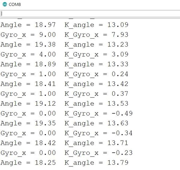
Notice that as you tilt the robot back and forth, the value for the tilt angle and angular velocity change accordingly.
Use Control Theory to Keep the Robot Upright
Up until now, you have seen how to calculate the tilt angle of the robot. In this section, we’ll use that information along with some control theory to write a program that will enable our self-balancing robot to stand upright on its wheels.
Before we open up the Arduino IDE, let’s take a brief look at some control theory.
How a PID Controller Works
A PID controller (proportional–integral–derivative controller) is one of the most common control systems used in robotics. It is an algorithm that can help you keep a variable (e.g. temperature in an oven, speed for a car, angle for an airplane, etc.) at a certain setpoint.
It works by continuously calculating the error between a desired value (i.e. setpoint) and the measured value. It then applies calculus to determine the correction that is needed to reduce the difference between the measured value and the desired value.
A common PID controller is the one in your cruise control system on your car. Imagine you had your cruise control set to a certain speed, like 60 miles per hour. If you tried to go up a hill, your car would slow down.
The PID controller algorithm in your cruise control calculates the difference between your measured speed and your desired speed (i.e. setpoint) of 60 miles per hour. It then uses some mathematics (three terms: the Proportional Term, Integral Term, and Derivative Term) to restore your speed to the desired speed by applying more engine power (and thereby, causing the wheels to turn faster). The cool thing about the PID controller is it offers smoother adjustments than if you were to code up a brute force control system like the following:
If (current speed > desired speed):
  Apply less engine power
Else
  Apply more engine power
That algorithm above would cause your car to jerk up and down in speed and wouldn’t be a smooth way to control your speed around 60 mph. If you are going slower than your desired speed, the car would accelerate upwards and might even overshoot to like 70 mph. If you are going too fast, the car might slow down too quickly and overshoot on the low end to some value (e.g. 45 mph). The driver in the car behind you would certainly think you’ve gone mad!
By using calculus, a PID controller (i.e. algorithm) helps the engine make smooth adjustments to keep your car moving at your desired speed. That’s PID in a nutshell.
You don’t need to master all the math behind a PID controller, but if you have some spare time one day, the best explanation of PID control is in Rick Anderson’s book Pro Arduino. In that book, he implements a basic PID controller step-by-step.
Just remember that a PID controller is like a thermostat in your house or cruise control in your car. When you want some measured variable to remain constant, a PID controller is a valuable algorithmic tool.
Write a Controller to Keep Your Robot Upright
We know how to measure the tilt angle and the angular velocity of our robot. In order to keep our robot self-balanced, we need to write a controller so the robot knows how to move the wheels to keep it from falling over due to gravity.
Here, we will write a controller using the theory we learned in the last section to keep our robot balanced on a flat surface.
Open up the Arduino IDE.
Add the PinChangeInt library. Go to this page on GitHub.
Click the green button that says “Clone or Download.”
Click the button that says “Download Zip”.
Go back to your Arduino IDE, and go to:
Sketch -> Include Library -> Add .Zip Library
Find the PinChangeInt library, and click Open in order to add it to your IDE.
Open a new sketch and save it as pi_controlled_self_balancing_robot.ino.
Type the following code:
#include <MsTimer2.h>        //internal timer 2
#include <PinChangeInt.h>    //This library file can make all pins on the REV4 board as external interrupts.
#include <MPU6050.h>      //MPU6050 library
#include <Wire.h>        //IIC library

MPU6050 mpu6050;     //Instantiate an MPU6050 object; name mpu6050
int16_t ax, ay, az, gx, gy, gz;     // Define three-axis acceleration, three-axis gyroscope variables

//TB6612 pins
const int right_R1=8;
const int right_R2=12;
const int PWM_R=10;
const int left_L1=7;
const int left_L2=6;
const int PWM_L=9;

///////////////////////angle parameters//////////////////////////////
float angle_X; //Calculate the tilt angle variable about the X axis from the acceleration
float angle_Y; //Calculate the tilt angle variable about the Y axis from the acceleration
float angle0 = 1; //Actual measured angle (ideally 0 degrees)
float Gyro_x,Gyro_y,Gyro_z;  //Angular angular velocity by gyroscope calculation
///////////////////////angle parameters//////////////////////////////

///////////////////////Kalman_Filter////////////////////////////
float Q_angle = 0.001;  //Covariance of gyroscope noise
float Q_gyro = 0.003;    //Covariance of gyroscope drift noise
float R_angle = 0.5;    //Covariance of accelerometer
char C_0 = 1;
float dt = 0.005; // The value of dt is the filter sampling time.
float K1 = 0.05; //a function containing the Kalman gain is used to calculate the deviation of the optimal estimate
float K_0,K_1,t_0,t_1;
float angle_err;
float q_bias;    //Gyro drift

float accelz = 0;
float angle;
float angleY_one;
float angle_speed;

float Pdot[4] = { 0, 0, 0, 0};
float P[2][2] = {{ 1, 0 }, { 0, 1 }};
float  PCt_0, PCt_1, E;
//////////////////////Kalman_Filter/////////////////////////

//////////////////////PID parameters///////////////////////////////
double kp = 34, ki = 0, kd = 0.62;                   //angle loop parameters
double kp_speed = 3.6, ki_speed = 0.080, kd_speed = 0;   // speed loop parameters
double setp0 = 0; //angle balance point
int PD_pwm;  //angle output
float pwm1=0,pwm2=0;

//////////////////Interrupt speed measurement/////////////////////////////
#define PinA_left 5  //external interrupts
#define PinA_right 4   //external interrupts
volatile long count_right = 0;//Used to calculate the pulse value calculated by the Hall encoder (the volatile long type is to ensure the value is valid)
volatile long count_left = 0;
int speedcc = 0;
//////////////////////pulse calculation/////////////////////////
int lz = 0;
int rz = 0;
int rpluse = 0;
int lpluse = 0;
int pulseright,pulseleft;
////////////////////////////////PI variable parameters//////////////////////////
float speeds_filterold=0;
float positions=0;
int flag1;
double PI_pwm;
int cc;
int speedout;
float speeds_filter;

void setup()
{
  // set the pins of motor to OUTPUT
  pinMode(right_R1,OUTPUT);
  pinMode(right_R2,OUTPUT);
  pinMode(left_L1,OUTPUT);
  pinMode(left_L2,OUTPUT);
  pinMode(PWM_R,OUTPUT);
  pinMode(PWM_L,OUTPUT);

  //assign initial state value
  digitalWrite(right_R1,1);
  digitalWrite(right_R2,0);
  digitalWrite(left_L1,0);
  digitalWrite(left_L2,1);
  analogWrite(PWM_R,0);
  analogWrite(PWM_L,0);

  pinMode(PinA_left, INPUT);  //speed code wheel input
  pinMode(PinA_right, INPUT);

  // join I2C bus
  Wire.begin();                            //join I2C bus sequence
  Serial.begin(9600);                       //open the serial monitor to set the baud rate to 9600
  delay(1500);
  mpu6050.initialize();                       //initialize MPU6050
  delay(2);

  //5ms; use timer2 to set timer interruption (note:using timer2 will affect the PWM output of pin3 pin11)
  MsTimer2::set(5, Interrupt_Service_Routine);    //5ms ; execute the function Interrupt_Service_Routine once
  MsTimer2::start();    //start interrupt
}

void loop()
{
  Serial.println(angle);
  delay(100);
  //Serial.println(PD_pwm);
  //Serial.println(pwm1);
  //Serial.println(pwm2);
  //Serial.print("pulseright = ");
  //Serial.println(pulseright);
  //Serial.print("pulseleft = ");
  //Serial.println(pulseleft);
  //Serial.println(PI_pwm);
  //Serial.println(speeds_filter);
  //Serial.println (positions);

  //External interrupt for calculating wheel speed
  attachPinChangeInterrupt(PinA_left, Code_left, CHANGE);          //PinA_left Level change triggers external interrupt; execute subfunction Code_left
  attachPinChangeInterrupt(PinA_right, Code_right, CHANGE);       //PinA_right Level change triggers external interrupt; execute subfunction Code_right
}

/////////////////////Hall calculation/////////////////////////
//left speed code wheel count
void Code_left()
{
  count_left ++;
}
//Right speed code wheel count
void Code_right()
{
  count_right ++;
}
////////////////////pulse calculation///////////////////////
void countpluse()
{
  lz = count_left;     //Assign the value counted by the code wheel to lz
  rz = count_right;

  count_left = 0;     //Clear the code counter count
  count_right = 0;

  lpluse = lz;
  rpluse = rz;

  if ((pwm1 < 0) && (pwm2 < 0))                     //judge the moving direction; if backwards(PWM, namely motor voltage is negative), pulse number is a negative number
  {
    rpluse = -rpluse;
    lpluse = -lpluse;
  }
  else if ((pwm1 > 0) && (pwm2 > 0))                 // if backwards(PWM, namely motor voltage is positive), pulse number is a positive number
  {
    rpluse = rpluse;
    lpluse = lpluse;
  }
  else if ((pwm1 < 0) && (pwm2 > 0))                 //Judge turning direction of the car;  turn left; Right pulse number is a positive number; Left pulse number is a negative number.
  {
    rpluse = rpluse;
    lpluse = -lpluse;
  }
  else if ((pwm1 > 0) && (pwm2 < 0))               //Judge turning direction of the car;  turn right; Right pulse number is a negative number; Left pulse number is a positive number.
  {
    rpluse = -rpluse;
    lpluse = lpluse;
  }

  //enter interrupts per 5ms; pulse number superposes
  pulseright += rpluse;
  pulseleft += lpluse;
}

/////////////////////////////////interrupts////////////////////////////
void Interrupt_Service_Routine()
{
  sei();  //Allow global interrupts
  countpluse();        //Pulse superposition subfunction
  mpu6050.getMotion6(&ax, &ay, &az, &gx, &gy, &gz);     //IIC to get MPU6050 six-axis data  ax ay az gx gy gz
  angle_calculate(ax, ay, az, gx, gy, gz, dt, Q_angle, Q_gyro, R_angle, C_0, K1);      //get angle and Kalman filtering
  PD();         //angle loop PD control
  anglePWM();

  cc++;
  if(cc>=8)     //5*8=40,40ms entering once speed PI algorithm
  {
    speedpiout();
    cc=0;  //Clear
  }
}
///////////////////////////////////////////////////////////

/////////////////////////////angle calculation///////////////////////
void angle_calculate(int16_t ax,int16_t ay,int16_t az,int16_t gx,int16_t gy,int16_t gz,float dt,float Q_angle,float Q_gyro,float R_angle,float C_0,float K1)
{
  float Angle = -atan2(ay , az) * (180/ PI);           //Radial rotation angle calculation formula; negative sign is direction processing
  Gyro_x = -gx / 131;              //The X-axis angular velocity calculated by the gyroscope; the negative sign is the direction processing
  Kalman_Filter(Angle, Gyro_x);            //Kalman Filtering
  //Rotation angle Z-axis parameter
  Gyro_z = -gz / 131;                      //Z-axis angular velocity
  //accelz = az / 16.4;

  float angleAx = -atan2(ax, az) * (180 / PI); //Calculate the angle with the x-axis
  Gyro_y = -gy / 131.00; //Y-axis angular velocity
  Yiorderfilter(angleAx, Gyro_y); //first-order filtering
}
////////////////////////////////////////////////////////////////

///////////////////////////////KalmanFilter/////////////////////
void Kalman_Filter(double angle_m, double gyro_m)
{
  angle += (gyro_m - q_bias) * dt;          //Prior estimate
  angle_err = angle_m - angle;

  Pdot[0] = Q_angle - P[0][1] - P[1][0];    //Differential of azimuth error covariance
  Pdot[1] = - P[1][1];
  Pdot[2] = - P[1][1];
  Pdot[3] = Q_gyro;

  P[0][0] += Pdot[0] * dt;    //A priori estimation error covariance differential integral
  P[0][1] += Pdot[1] * dt;
  P[1][0] += Pdot[2] * dt;
  P[1][1] += Pdot[3] * dt;

  //Intermediate variable of matrix multiplication
  PCt_0 = C_0 * P[0][0];
  PCt_1 = C_0 * P[1][0];
  //Denominator
  E = R_angle + C_0 * PCt_0;
  //gain value
  K_0 = PCt_0 / E;
  K_1 = PCt_1 / E;

  t_0 = PCt_0;  //Intermediate variable of matrix multiplication
  t_1 = C_0 * P[0][1];

  P[0][0] -= K_0 * t_0;    //Posterior estimation error covariance
  P[0][1] -= K_0 * t_1;
  P[1][0] -= K_1 * t_0;
  P[1][1] -= K_1 * t_1;

  q_bias += K_1 * angle_err;    //Posterior estimate
  angle_speed = gyro_m - q_bias;   //The differential of the output value gives the optimal angular velocity
  angle += K_0 * angle_err; ////Posterior estimation to get the optimal angle
}

/////////////////////first-order filtering/////////////////
void Yiorderfilter(float angle_m, float gyro_m)
{
  angleY_one = K1 * angle_m + (1 - K1) * (angleY_one + gyro_m * dt);
}

//////////////////angle PD////////////////////
void PD()
{
  PD_pwm = kp * (angle + angle0) + kd * angle_speed; //PD angle loop control
}

//////////////////speed PI////////////////////
void speedpiout()
{
  float speeds = (pulseleft + pulseright) * 1.0;      //Vehicle speed  pulse value
  pulseright = pulseleft = 0;      //Clear
  speeds_filterold *= 0.7;         //first-order complementary filtering
  speeds_filter = speeds_filterold + speeds * 0.3;
  speeds_filterold = speeds_filter;
  positions += speeds_filter;
  positions = constrain(positions, -3550,3550);    //Anti-integral saturation
  PI_pwm = ki_speed * (setp0 - positions) + kp_speed * (setp0 - speeds_filter);      //speed loop control PI
}
//////////////////speed PI////////////////////


////////////////////////////PWM end value/////////////////////////////
void anglePWM()
{
  pwm2=-PD_pwm - PI_pwm ;           //assign the final value of PWM to motor
  pwm1=-PD_pwm - PI_pwm ;

  if(pwm1>255)             //limit PWM value not greater than 255
  {
    pwm1=255;
  }
  if(pwm1<-255)
  {
    pwm1=-255;
  }
  if(pwm2>255)
  {
    pwm2=255;
  }
  if(pwm2<-255)
  {
    pwm2=-255;
  }

  // When the self-balancing trolley’s tilt angle gets less than a certain angle,
  // the motor will stop.

  if(angle>25 || angle<-25)
  {
    pwm1=pwm2=0;
  }

  // Determine the motor’s steering and speed by the positive and negative of PWM
  if(pwm2>=0)
  {
    digitalWrite(left_L1,LOW);
    digitalWrite(left_L2,HIGH);
    analogWrite(PWM_L,pwm2);
  }
  else
  {
    digitalWrite(left_L1,HIGH);
    digitalWrite(left_L2,LOW);
    analogWrite(PWM_L,-pwm2);
  }

  if(pwm1>=0)
  {
    digitalWrite(right_R1,HIGH);
    digitalWrite(right_R2,LOW);
    analogWrite(PWM_R,pwm1);
  }
  else
  {
    digitalWrite(right_R1,LOW);
    digitalWrite(right_R2,HIGH);
    analogWrite(PWM_R,-pwm1);
  }
}
Upload the code to your Arduino.
Unplug your Arduino from your desktop or laptop computer.
Add three 3.7V batteries to the battery holder.
Plug the battery holder into the Balance Shield (not the Arduino board underneath).
Now, hold your robot stationary and upright with your hand with the wheels touching a flat surface (e.g. floor, table, desk, etc.).
Turn the switch on the side of the Balance Shield to the ON position.
The robot should self-balance.
If the motors fire and cause the robot to shoot away, grab the robot, and try again. Hold the robot really still and upright as you switch the toggle to ON on the Balance Shield. For the first few seconds that the robot is on, hold it still, the robot should begin to self-balance.
Another thing you can do, if you are having trouble is to tweak the angle in this line of code:
  // When the self-balancing trolley’s tilt angle gets less than
  // a certain angle, the motor will stop.

  if(angle>25 || angle<-25)
  {
    pwm1=pwm2=0;
  }
I used 25, but you can try other values like 50 or even 10. Don’t give up. Keep trying different numbers until you get the robot to self-balance. In robotics, it is almost always the rule that things don’t work as you expect the first time around.
Here is another piece of code courtesy of Keyestudio. This particular code makes the move around in circles. By changing the value assigned to the “val” variable on this line, you can make the robot go forwards (‘F’), backwards (‘B’), left (‘L’), right (‘R’), and stop (‘S’).
I saved this code as go_forward_pi_controlled_self_balancing_robot.
#include <MsTimer2.h>        //internal timer 2
#include <PinChangeInt.h>    //this library can make all pins of arduino REV4 as external interrupt
#include <MPU6050.h>      //MPU6050 library
#include <Wire.h>        //IIC communication library

MPU6050 mpu6050;     //Instantiate an MPU6050 object; name mpu6050
int16_t ax, ay, az, gx, gy, gz;     //Define three-axis acceleration, three-axis gyroscope variables

//TB6612 pins
const int right_R1=8;
const int right_R2=12;
const int PWM_R=10;
const int left_L1=7;
const int left_L2=6;
const int PWM_L=9;

///////////////////////angle parameters//////////////////////////////
float angle_X; //calculate the inclined angle variable of X-axis by accelerometer
float angle_Y; //calculate the inclined angle variable of Y-axis by accelerometer
float angle0 = 1; //Actual measured angle (ideally 0 degrees)
float Gyro_x,Gyro_y,Gyro_z;  //Angular angular velocity for gyroscope calculation
///////////////////////angle parameters//////////////////////////////

///////////////////////Kalman_Filter////////////////////////////
float Q_angle = 0.001;  //Covariance of gyroscope noise
float Q_gyro = 0.003;    //Covariance of gyroscope drift noise
float R_angle = 0.5;    //Covariance of accelerometer
char C_0 = 1;
float dt = 0.005; //The value of dt is the filter sampling time
float K1 = 0.05; //  a function containing the Kalman gain; used to calculate the deviation of the optimal estimate
float K_0,K_1,t_0,t_1;
float angle_err;
float q_bias;    //gyroscope drift

float accelz = 0;
float angle;
float angleY_one;
float angle_speed;

float Pdot[4] = { 0, 0, 0, 0};
float P[2][2] = {{ 1, 0 }, { 0, 1 }};
float  PCt_0, PCt_1, E;
//////////////////////Kalman_Filter/////////////////////////

//////////////////////PID parameters///////////////////////////////
double kp = 34, ki = 0, kd = 0.62;                   //angle loop parameters
double kp_speed = 3.6, ki_speed = 0.080, kd_speed = 0;   // speed loop parameters
double kp_turn = 24, ki_turn = 0, kd_turn = 0.08;       // steering loop parameters
double setp0 = 0; //Angle balance point
int PD_pwm;  //angle output
float pwm1=0,pwm2=0;

//////////////////Interrupt speed count/////////////////////////////
#define PinA_left 5  //external interrupt
#define PinA_right 4   //external interrupt
volatile long count_right = 0;//Used to calculate the pulse value calculated by the Hall encoder (the volatile long type is to ensure the value is valid)
volatile long count_left = 0;
int speedcc = 0;
//////////////////////pulse count/////////////////////////
int lz = 0;
int rz = 0;
int rpluse = 0;
int lpluse = 0;
int pulseright,pulseleft;
////////////////////////////////PI variable parameter//////////////////////////
float speeds_filterold=0;
float positions=0;
int flag1;
double PI_pwm;
int cc;
int speedout;
float speeds_filter;

//////////////////////////////steering PD///////////////////
int turnmax,turnmin,turnout;
float Turn_pwm = 0;
int zz=0;
int turncc=0;

//Remote control or Bluetooth//
int front = 0;//go front variable
int back = 0;//go back variable
int left = 0;//turn left
int right = 0;//turn right
char val;

void setup()
{
  //set the motor control pins to OUTPUT
  pinMode(right_R1,OUTPUT);
  pinMode(right_R2,OUTPUT);
  pinMode(left_L1,OUTPUT);
  pinMode(left_L2,OUTPUT);
  pinMode(PWM_R,OUTPUT);
  pinMode(PWM_L,OUTPUT);

  //assign initial state value
  digitalWrite(right_R1,1);
  digitalWrite(right_R2,0);
  digitalWrite(left_L1,0);
  digitalWrite(left_L2,1);
  analogWrite(PWM_R,0);
  analogWrite(PWM_L,0);

  pinMode(PinA_left, INPUT);  //Speed encoder input
  pinMode(PinA_right, INPUT);

  // join I2C bus
  Wire.begin();                            //join I2C bus sequence
  Serial.begin(9600);                       //open the serial monitor and set the baud rate to 9600
  delay(1500);
  mpu6050.initialize();                       //initialize MPU6050
  delay(2);

  //5ms; use timer2 to set timer interruption (note:using timer2 will affect the PWM output of pin3 pin11)
  MsTimer2::set(5, Interrupt_Service_Routine);    //5ms ; execute the function Interrupt_Service_Routine once
  MsTimer2::start();    //start interrupt
}

void loop()
{
  Serial.print(angle_speed);
  Serial.print("     ");
  Serial.println(Gyro_x);

  //Serial.println(angle);
  //delay(100);
  //Serial.println(PD_pwm);
  //Serial.println(pwm1);
  //Serial.println(pwm2);
  //Serial.print("pulseright = ");
  //Serial.println(pulseright);
  //Serial.print("pulseleft = ");
  //Serial.println(pulseleft);
  //Serial.println(PI_pwm);
  //Serial.println(speeds_filter);
  //Serial.println (positions);
  //Serial.println(Turn_pwm);
  //Serial.println(Gyro_z);
  //Serial.println(Turn_pwm);

  // Used for Bluetooth control
  // if(Serial.available()) {
  // val = Serial.read();      //assign the value read from serial port to val
  // Serial.println(val);
  val = 'R';
  switch(val)             //switch statement
  {
    case 'F': front=250; break;       //if val equals to F,front=250,balance robot goes front.
    case 'B': back=-250; break;       //go back
    case 'L': left=1; break;    //turn left
    case 'R': right=1; break;                         // turn right
    case 'S': front=0,back=0,left=0,right=0;break;    //stop
      case 'D': Serial.print(angle);break;    //when receiving ‘D’,send value of angle to APP
   }


  //}

  //external interrupt; used to calculate the wheel speed
  attachPinChangeInterrupt(PinA_left, Code_left, CHANGE);          //PinA_left  Level change triggers external interrupt;  execute subfunction Code_left
  attachPinChangeInterrupt(PinA_right, Code_right, CHANGE);       //PinA_right Level change triggers external interrupt;  execute subfunction Code_right
}

/////////////////////Hall count/////////////////////////
//left speed encoder count
void Code_left()
{
  count_left ++;
}
//right speed encoder count
void Code_right()
{
  count_right ++;
}
////////////////////pulse count///////////////////////
void countpluse()
{
  lz = count_left;     //assign the value counted by encoder to lz
  rz = count_right;

  count_left = 0;     //clear the count quantity
  count_right = 0;

  lpluse = lz;
  rpluse = rz;

  if ((pwm1 < 0) && (pwm2 < 0))                     //judge the moving direction of balance robot; if go back (PWM the motor voltage is negative), the number of pulses is negative.
  {
    rpluse = -rpluse;
    lpluse = -lpluse;
  }
  else if ((pwm1 > 0) && (pwm2 > 0))                 // if go back (PWM the motor voltage is positive) , the number of pulses is positive.
  {
    rpluse = rpluse;
    lpluse = lpluse;
  }
  else if ((pwm1 < 0) && (pwm2 > 0))                 //judge the moving direction of balance robot; if turn left, right pulse is positive but left pulse is negative.
  {
    rpluse = rpluse;
    lpluse = -lpluse;
  }
  else if ((pwm1 > 0) && (pwm2 < 0))               //judge the moving direction of balance robot; if turn right , right pulse is negative but left pulse is positive.
  {
    rpluse = -rpluse;
    lpluse = lpluse;
  }

  //entering interrupt per 5ms,pulse will plus
  pulseright += rpluse;
  pulseleft += lpluse;
}

/////////////////////////////////interrupt ////////////////////////////
void Interrupt_Service_Routine()
{
  sei();  //allow overall interrupt
  countpluse();        //pulse count subfunction
  mpu6050.getMotion6(&ax, &ay, &az, &gx, &gy, &gz);     //IIC to get MPU6050 six-axis data ax ay az gx gy gz
  angle_calculate(ax, ay, az, gx, gy, gz, dt, Q_angle, Q_gyro, R_angle, C_0, K1);      //get the angle and Kalman filtering
  PD();         //PD control of angle loop
  anglePWM();

  cc++;
  if(cc>=8)     //5*8=40,40ms entering PI count of speed once
  {
    speedpiout();
    cc=0;  // Clear
  }
  turncc++;
  if(turncc>4)       //20ms entering PI count of steering once
  {
    turnspin();
    turncc=0;     //Clear
  }
}
///////////////////////////////////////////////////////////

/////////////////////////////tilt angle calculation///////////////////////
void angle_calculate(int16_t ax,int16_t ay,int16_t az,int16_t gx,int16_t gy,int16_t gz,float dt,float Q_angle,float Q_gyro,float R_angle,float C_0,float K1)
{
  float Angle = -atan2(ay , az) * (180/ PI);           //Radial rotation angle calculation formula; the negative sign is direction processing.
  Gyro_x = -gx / 131;              //The X-axis angular velocity calculated by the gyroscope ; the negative sign is the direction processing.
  Kalman_Filter(Angle, Gyro_x);            // Kalman Filter
  // Z-axis angular velocity
  Gyro_z = -gz / 131;                      //speed of Z-axis
  //accelz = az / 16.4;

  float angleAx = -atan2(ax, az) * (180 / PI); //calculate the included angle of X-axis
  Gyro_y = -gy / 131.00; //angle speed of Y-axis
  Yiorderfilter(angleAx, Gyro_y); //first-order filtering
}
////////////////////////////////////////////////////////////////

///////////////////////////////KalmanFilter/////////////////////
void Kalman_Filter(double angle_m, double gyro_m)
{
  angle += (gyro_m - q_bias) * dt;          //prior estimate
  angle_err = angle_m - angle;

  Pdot[0] = Q_angle - P[0][1] - P[1][0];    //The differential of the covariance of the prior estimate error
  Pdot[1] = - P[1][1];
  Pdot[2] = - P[1][1];
  Pdot[3] = Q_gyro;

  P[0][0] += Pdot[0] * dt;    //The integral of the covariance differential of the prior estimate error
  P[0][1] += Pdot[1] * dt;
  P[1][0] += Pdot[2] * dt;
  P[1][1] += Pdot[3] * dt;

  //Intermediate variables in matrix multiplication
  PCt_0 = C_0 * P[0][0];
  PCt_1 = C_0 * P[1][0];
  //denominator
  E = R_angle + C_0 * PCt_0;
  //gain value
  K_0 = PCt_0 / E;
  K_1 = PCt_1 / E;

  t_0 = PCt_0;  //Intermediate variables in matrix multiplication
  t_1 = C_0 * P[0][1];

  P[0][0] -= K_0 * t_0;    //the covariance of the prior estimate error
  P[0][1] -= K_0 * t_1;
  P[1][0] -= K_1 * t_0;
  P[1][1] -= K_1 * t_1;

  q_bias += K_1 * angle_err;    //posterior estimate
  angle_speed = gyro_m - q_bias;   //The differential of the output value; get the optimal angular velocity
  angle += K_0 * angle_err; ////posterior estimate; get the optimal angular velocity
}

/////////////////////first-order filtering/////////////////
void Yiorderfilter(float angle_m, float gyro_m)
{
  angleY_one = K1 * angle_m + (1 - K1) * (angleY_one + gyro_m * dt);
}

//////////////////angle PD////////////////////
void PD()
{
  PD_pwm = kp * (angle + angle0) + kd * angle_speed; //PD angle loop control
}

//////////////////speed PI////////////////////
void speedpiout()
{
  float speeds = (pulseleft + pulseright) * 1.0;      //pulse value of speed
  pulseright = pulseleft = 0;      //Clear
  speeds_filterold *= 0.7;         //first-order complementary filtering
  speeds_filter = speeds_filterold + speeds * 0.3;
  speeds_filterold = speeds_filter;
  positions += speeds_filter;
  positions += front;             //Forward control fusion
  positions += back;              //backward control fusion
  positions = constrain(positions, -3550,3550);    //Anti-integral saturation
  PI_pwm = ki_speed * (setp0 - positions) + kp_speed * (setp0 - speeds_filter);      //speed loop controlling PI
}
//////////////////speed PI////////////////////

///////////////////////////steering/////////////////////////////////
void turnspin()
{
  int flag = 0;      //
  float turnspeed = 0;
  float rotationratio = 0;

  if (left == 1 || right == 1)
  {
    if (flag == 0)                             //judge the speed before turning; increase the car’s flexibility.
    {
      turnspeed = ( pulseright + pulseleft);                      //current speed of car; pulse expression
      flag=1;
    }
    if (turnspeed < 0)                                 //Absolute value of the car's current speed
    {
      turnspeed = -turnspeed;
    }
    if(left==1||right==1)         //if press left key or right key
    {
     turnmax=3;          //maximum value of turning
     turnmin=-3;         // minimum value of turning
    }
    rotationratio = 5 / turnspeed;          //set the value by speed
    if (rotationratio < 0.5)
    {
      rotationratio = 0.5;
    }

    if (rotationratio > 5)
    {
      rotationratio = 5;
    }
  }
  else
  {
    rotationratio = 0.5;
    flag = 0;
    turnspeed = 0;
  }
  if (left ==1)//plus by direction parameter
  {
    turnout += rotationratio;
  }
  else if (right == 1 )//plus by direction parameter
  {
    turnout -= rotationratio;
  }
  else turnout = 0;
  if (turnout > turnmax)   turnout = turnmax;//the max value setting of amplitude
  if (turnout < turnmin)   turnout = turnmin;//the min value setting of amplitude

  Turn_pwm = -turnout * kp_turn - Gyro_z * kd_turn;//The rotation PD algorithm controls the fusion speed and Z axis rotation positioning
}
///////////////////////////turning/////////////////////////////////

////////////////////////////PWM end value/////////////////////////////
void anglePWM()
{
  pwm2=-PD_pwm - PI_pwm + Turn_pwm;           //assign the end value of PWM to motor
  pwm1=-PD_pwm - PI_pwm - Turn_pwm;

  if(pwm1>255)             //limit the PWM value not more than 255
  {
    pwm1=255;
  }
  if(pwm1<-255)
  {
    pwm1=-255;
  }
  if(pwm2>255)
  {
    pwm2=255;
  }
  if(pwm2<-255)
  {
    pwm2=-255;
  }

  if(angle>25 || angle<-25)      //if tilt angle is greater than 25° , motor will stop.
  {
    pwm1=pwm2=0;
  }

  // Determine the motor’s steering and speed by the positive and negative of PWM
  if(pwm2>=0)
  {
    digitalWrite(left_L1,LOW);
    digitalWrite(left_L2,HIGH);
    analogWrite(PWM_L,pwm2);
  }
  else
  {
    digitalWrite(left_L1,HIGH);
    digitalWrite(left_L2,LOW);
    analogWrite(PWM_L,-pwm2);
  }

  if(pwm1>=0)
  {
    digitalWrite(right_R1,HIGH);
    digitalWrite(right_R2,LOW);
    analogWrite(PWM_R,pwm1);
  }
  else
  {
    digitalWrite(right_R1,LOW);
    digitalWrite(right_R2,HIGH);
    analogWrite(PWM_R,-pwm1);
  }
}
Challenge Exercise: Connect the Arduino (via the pins in the Balance Shield) to a Bluetooth Receiver
That’s it for this tutorial. At this stage, if you want to dive deeper, you can connect your Arduino (via the pins above on the Balance Shield) to a Bluetooth dongle, like the HC-05 Wireless Bluetooth RF Transceiver.
You can see in the comments of the code in the previous section that it is partially setup to receive commands from a Bluetooth dongle.
  // Used for Bluetooth control
  // if(Serial.available()) {
  // val = Serial.read(); //assign the value read from serial port to val
  // Serial.println(val);
  val = 'R';
  switch(val)             //switch statement
  {
    case 'F': front=250; break; //if val=F,front=250, bot goes forward.
    case 'B': back=-250; break; //go back
    case 'L': left=1; break;  //turn left
    case 'R': right=1; break; // turn right
    case 'S': front=0,back=0,left=0,right=0;break;  //stop
    case 'D': Serial.print(angle);break;  //when receiving ‘D’,send value of angle to APP
   }
With some code additions and modifications, you can hook up your Arduino to a Bluetooth dongle so that you can control the robot’s movement directly.
In addition to connecting your Arduino to something like the HC-05 Wireless Bluetooth RF Transceiver, you would need to download a Bluetooth smartphone app (e.g. the Serial Bluetooth Terminal app from the Google Play store). You would then send commands (e.g. type in F on your app) to the Arduino (via the HC-05) from your smartphone. The Arduino would read these commands from its serial port, and the robot would move in the direction of your command.
This page here shows you how to wire the dongle to your Arduino. Then below that, I show the code you would need to add to your self-balancing robot code from the previous section in order to make the whole thing work.
That’s it for now. Hope you enjoyed this tutorial. Keep building!