In this tutorial, I will show you how to estimate the ArUco marker pose using ROS 2, OpenCV, and Gazebo.
Here is the output you will be able to generate by completing this tutorial:
Prerequisites
You can find the code for this post here on GitHub.
Directions
Make sure you have the calibration_chessboard.yaml file inside the following folder. This file contains the parameters for the camera.
~/dev_ws/src/two_wheeled_robot/scripts/
Inside this folder, make sure you have the aruco_marker_pose_estimation_tf.py script.
#!/usr/bin/env python3

# Publishes a coordinate transformation between an ArUco marker and a camera
# Author:
# - Addison Sears-Collins
# - https://automaticaddison.com

# Import the necessary ROS 2 libraries
import rclpy # Python library for ROS 2
from rclpy.node import Node # Handles the creation of nodes
from rclpy.qos import qos_profile_sensor_data # Uses Best Effort reliability for camera
from cv_bridge import CvBridge # Package to convert between ROS and OpenCV Images
from geometry_msgs.msg import TransformStamped # Handles TransformStamped message
from sensor_msgs.msg import Image # Image is the message type
from tf2_ros import TransformBroadcaster

# Import Python libraries
import cv2 # OpenCV library
import numpy as np # Import Numpy library
from scipy.spatial.transform import Rotation as R

# The different ArUco dictionaries built into the OpenCV library.
ARUCO_DICT = {
  "DICT_4X4_50": cv2.aruco.DICT_4X4_50,
  "DICT_4X4_100": cv2.aruco.DICT_4X4_100,
  "DICT_4X4_250": cv2.aruco.DICT_4X4_250,
  "DICT_4X4_1000": cv2.aruco.DICT_4X4_1000,
  "DICT_5X5_50": cv2.aruco.DICT_5X5_50,
  "DICT_5X5_100": cv2.aruco.DICT_5X5_100,
  "DICT_5X5_250": cv2.aruco.DICT_5X5_250,
  "DICT_5X5_1000": cv2.aruco.DICT_5X5_1000,
  "DICT_6X6_50": cv2.aruco.DICT_6X6_50,
  "DICT_6X6_100": cv2.aruco.DICT_6X6_100,
  "DICT_6X6_250": cv2.aruco.DICT_6X6_250,
  "DICT_6X6_1000": cv2.aruco.DICT_6X6_1000,
  "DICT_7X7_50": cv2.aruco.DICT_7X7_50,
  "DICT_7X7_100": cv2.aruco.DICT_7X7_100,
  "DICT_7X7_250": cv2.aruco.DICT_7X7_250,
  "DICT_7X7_1000": cv2.aruco.DICT_7X7_1000,
  "DICT_ARUCO_ORIGINAL": cv2.aruco.DICT_ARUCO_ORIGINAL
}

class ArucoNode(Node):
  """
  Create an ArucoNode class, which is a subclass of the Node class.
  """
  def __init__(self):
    """
    Class constructor to set up the node
    """
    # Initiate the Node class's constructor and give it a name
    super().__init__('aruco_node')

    # Declare parameters
    self.declare_parameter("aruco_dictionary_name", "DICT_ARUCO_ORIGINAL")
    self.declare_parameter("aruco_marker_side_length", 0.05)
    self.declare_parameter("camera_calibration_parameters_filename", "/home/focalfossa/dev_ws/src/two_wheeled_robot/scripts/calibration_chessboard.yaml")
    self.declare_parameter("image_topic", "/depth_camera/image_raw")
    self.declare_parameter("aruco_marker_name", "aruco_marker")

    # Read parameters
    aruco_dictionary_name = self.get_parameter("aruco_dictionary_name").get_parameter_value().string_value
    self.aruco_marker_side_length = self.get_parameter("aruco_marker_side_length").get_parameter_value().double_value
    self.camera_calibration_parameters_filename = self.get_parameter(
      "camera_calibration_parameters_filename").get_parameter_value().string_value
    image_topic = self.get_parameter("image_topic").get_parameter_value().string_value
    self.aruco_marker_name = self.get_parameter("aruco_marker_name").get_parameter_value().string_value

    # Check that we have a valid ArUco marker
    if ARUCO_DICT.get(aruco_dictionary_name, None) is None:
      self.get_logger().info("[INFO] ArUCo tag of '{}' is not supported".format(
        args["type"]))

    # Load the camera parameters from the saved file
    cv_file = cv2.FileStorage(
      self.camera_calibration_parameters_filename, cv2.FILE_STORAGE_READ)
    self.mtx = cv_file.getNode('K').mat()
    self.dst = cv_file.getNode('D').mat()
    cv_file.release()

    # Load the ArUco dictionary
    self.get_logger().info("[INFO] detecting '{}' markers...".format(
  	  aruco_dictionary_name))
    self.this_aruco_dictionary = cv2.aruco.Dictionary_get(ARUCO_DICT[aruco_dictionary_name])
    self.this_aruco_parameters = cv2.aruco.DetectorParameters_create()

    # Create the subscriber. This subscriber will receive an Image
    # from the image_topic.
    self.subscription = self.create_subscription(
      Image,
      image_topic,
      self.listener_callback,
      qos_profile=qos_profile_sensor_data)
    self.subscription # prevent unused variable warning

    # Initialize the transform broadcaster
    self.tfbroadcaster = TransformBroadcaster(self)

    # Used to convert between ROS and OpenCV images
    self.bridge = CvBridge()

  def listener_callback(self, data):
    """
    Callback function.
    """
    # Display the message on the console
    self.get_logger().info('Receiving video frame')

    # Convert ROS Image message to OpenCV image
    current_frame = self.bridge.imgmsg_to_cv2(data)

    # Detect ArUco markers in the video frame
    (corners, marker_ids, rejected) = cv2.aruco.detectMarkers(
      current_frame, self.this_aruco_dictionary, parameters=self.this_aruco_parameters,
      cameraMatrix=self.mtx, distCoeff=self.dst)

    # Check that at least one ArUco marker was detected
    if marker_ids is not None:

      # Draw a square around detected markers in the video frame
      cv2.aruco.drawDetectedMarkers(current_frame, corners, marker_ids)

      # Get the rotation and translation vectors
      rvecs, tvecs, obj_points = cv2.aruco.estimatePoseSingleMarkers(
        corners,
        self.aruco_marker_side_length,
        self.mtx,
        self.dst)

      # The pose of the marker is with respect to the camera lens frame.
      # Imagine you are looking through the camera viewfinder,
      # the camera lens frame's:
      # x-axis points to the right
      # y-axis points straight down towards your toes
      # z-axis points straight ahead away from your eye, out of the camera
      for i, marker_id in enumerate(marker_ids):

        # Create the coordinate transform
        t = TransformStamped()
        t.header.stamp = self.get_clock().now().to_msg()
        t.header.frame_id = 'camera_depth_frame'
        t.child_frame_id = self.aruco_marker_name

        # Store the translation (i.e. position) information
        t.transform.translation.x = tvecs[i][0][0]
        t.transform.translation.y = tvecs[i][0][1]
        t.transform.translation.z = tvecs[i][0][2]

        # Store the rotation information
        rotation_matrix = np.eye(4)
        rotation_matrix[0:3, 0:3] = cv2.Rodrigues(np.array(rvecs[i][0]))[0]
        r = R.from_matrix(rotation_matrix[0:3, 0:3])
        quat = r.as_quat()

        # Quaternion format
        t.transform.rotation.x = quat[0]
        t.transform.rotation.y = quat[1]
        t.transform.rotation.z = quat[2]
        t.transform.rotation.w = quat[3]

        # Send the transform
        self.tfbroadcaster.sendTransform(t)

        # Draw the axes on the marker
        cv2.aruco.drawAxis(current_frame, self.mtx, self.dst, rvecs[i], tvecs[i], 0.05)

    # Display image for testing
    cv2.imshow("camera", current_frame)
    cv2.waitKey(1)

def main(args=None):

  # Initialize the rclpy library
  rclpy.init(args=args)

  # Create the node
  aruco_node = ArucoNode()

  # Spin the node so the callback function is called.
  rclpy.spin(aruco_node)

  # Destroy the node explicitly
  # (optional - otherwise it will be done automatically
  # when the garbage collector destroys the node object)
  aruco_node.destroy_node()

  # Shutdown the ROS client library for Python
  rclpy.shutdown()

if __name__ == '__main__':
  main()
Make sure you enable it to execute.
cd ~/dev_ws/src/two_wheeled_robot/scripts/
chmod +x aruco_marker_pose_estimation_tf.py
Update the package.xml file with the necessary package dependencies.
Create a launch file.
cd ~/dev_ws/src/two_wheeled_robot/launch/hospital_world/
gedit hospital_world_connect_to_charging_dock_v4.launch.py
# Author: Addison Sears-Collins
# Date: January 10, 2022
# Description: Launch a two-wheeled robot using the ROS 2 Navigation Stack.
#              The spawning of the robot is performed by the Gazebo-ROS spawn_entity node.
#              The robot must be in both SDF and URDF format.
#              If you want to spawn the robot in a pose other than the default, be sure to set that inside
#              the nav2_params_path yaml file: amcl ---> initial_pose: [x, y, z, yaw]
#              The robot will return to the charging dock when the /battery_status percentage is low.
# https://automaticaddison.com

import os
from launch import LaunchDescription
from launch.actions import DeclareLaunchArgument, IncludeLaunchDescription
from launch.conditions import IfCondition, UnlessCondition
from launch.launch_description_sources import PythonLaunchDescriptionSource
from launch.substitutions import Command, LaunchConfiguration, PythonExpression
from launch_ros.actions import Node
from launch_ros.substitutions import FindPackageShare

def generate_launch_description():
  package_name = 'two_wheeled_robot'
  robot_name_in_model = 'two_wheeled_robot'
  default_launch_dir = 'launch'
  gazebo_models_path = 'models'
  map_file_path = 'maps/hospital_world/hospital_world.yaml'
  nav2_params_path = 'params/hospital_world/nav2_connect_to_charging_dock_params.yaml'
  robot_localization_file_path = 'config/ekf.yaml'
  rviz_config_file_path = 'rviz/hospital_world/nav2_config_with_depth_camera.rviz'
  sdf_model_path = 'models/two_wheeled_robot_with_camera_description/model.sdf'
  urdf_file_path = 'urdf/two_wheeled_robot_with_camera.urdf'
  world_file_path = 'worlds/hospital.world'
  nav_to_charging_dock_script = 'navigate_to_charging_dock_v2.py'

  # Pose where we want to spawn the robot
  spawn_x_val = '0.0'
  spawn_y_val = '2.0'
  spawn_z_val = '0.25'
  spawn_yaw_val = '0.0'

  ########## You do not need to change anything below this line ###############

  # Set the path to different files and folders.
  pkg_gazebo_ros = FindPackageShare(package='gazebo_ros').find('gazebo_ros')
  pkg_share = FindPackageShare(package=package_name).find(package_name)
  default_launch_dir = os.path.join(pkg_share, default_launch_dir)
  default_urdf_model_path = os.path.join(pkg_share, urdf_file_path)
  robot_localization_file_path = os.path.join(pkg_share, robot_localization_file_path)
  default_rviz_config_path = os.path.join(pkg_share, rviz_config_file_path)
  world_path = os.path.join(pkg_share, world_file_path)
  gazebo_models_path = os.path.join(pkg_share, gazebo_models_path)
  os.environ["GAZEBO_MODEL_PATH"] = gazebo_models_path
  nav2_dir = FindPackageShare(package='nav2_bringup').find('nav2_bringup')
  nav2_launch_dir = os.path.join(nav2_dir, 'launch')
  sdf_model_path = os.path.join(pkg_share, sdf_model_path)
  static_map_path = os.path.join(pkg_share, map_file_path)
  nav2_params_path = os.path.join(pkg_share, nav2_params_path)
  nav2_bt_path = FindPackageShare(package='nav2_bt_navigator').find('nav2_bt_navigator')

  # Launch configuration variables specific to simulation
  autostart = LaunchConfiguration('autostart')
  headless = LaunchConfiguration('headless')
  map_yaml_file = LaunchConfiguration('map')
  namespace = LaunchConfiguration('namespace')
  params_file = LaunchConfiguration('params_file')
  rviz_config_file = LaunchConfiguration('rviz_config_file')
  sdf_model = LaunchConfiguration('sdf_model')
  slam = LaunchConfiguration('slam')
  urdf_model = LaunchConfiguration('urdf_model')
  use_namespace = LaunchConfiguration('use_namespace')
  use_robot_state_pub = LaunchConfiguration('use_robot_state_pub')
  use_rviz = LaunchConfiguration('use_rviz')
  use_sim_time = LaunchConfiguration('use_sim_time')
  use_simulator = LaunchConfiguration('use_simulator')
  world = LaunchConfiguration('world')

  # Map fully qualified names to relative ones so the node's namespace can be prepended.
  # In case of the transforms (tf), currently, there doesn't seem to be a better alternative
  # https://github.com/ros/geometry2/issues/32
  # https://github.com/ros/robot_state_publisher/pull/30
  # TODO(orduno) Substitute with `PushNodeRemapping`
  #              https://github.com/ros2/launch_ros/issues/56
  remappings = [('/tf', 'tf'),
                ('/tf_static', 'tf_static')]

  # Declare the launch arguments
  declare_namespace_cmd = DeclareLaunchArgument(
    name='namespace',
    default_value='',
    description='Top-level namespace')

  declare_use_namespace_cmd = DeclareLaunchArgument(
    name='use_namespace',
    default_value='false',
    description='Whether to apply a namespace to the navigation stack')

  declare_autostart_cmd = DeclareLaunchArgument(
    name='autostart',
    default_value='true',
    description='Automatically startup the nav2 stack')

  declare_map_yaml_cmd = DeclareLaunchArgument(
    name='map',
    default_value=static_map_path,
    description='Full path to map file to load')

  declare_params_file_cmd = DeclareLaunchArgument(
    name='params_file',
    default_value=nav2_params_path,
    description='Full path to the ROS2 parameters file to use for all launched nodes')

  declare_rviz_config_file_cmd = DeclareLaunchArgument(
    name='rviz_config_file',
    default_value=default_rviz_config_path,
    description='Full path to the RVIZ config file to use')

  declare_sdf_model_path_cmd = DeclareLaunchArgument(
    name='sdf_model',
    default_value=sdf_model_path,
    description='Absolute path to robot sdf file')

  declare_simulator_cmd = DeclareLaunchArgument(
    name='headless',
    default_value='False',
    description='Whether to execute gzclient')

  declare_slam_cmd = DeclareLaunchArgument(
    name='slam',
    default_value='False',
    description='Whether to run SLAM')

  declare_urdf_model_path_cmd = DeclareLaunchArgument(
    name='urdf_model',
    default_value=default_urdf_model_path,
    description='Absolute path to robot urdf file')

  declare_use_robot_state_pub_cmd = DeclareLaunchArgument(
    name='use_robot_state_pub',
    default_value='True',
    description='Whether to start the robot state publisher')

  declare_use_rviz_cmd = DeclareLaunchArgument(
    name='use_rviz',
    default_value='True',
    description='Whether to start RVIZ')

  declare_use_sim_time_cmd = DeclareLaunchArgument(
    name='use_sim_time',
    default_value='true',
    description='Use simulation (Gazebo) clock if true')

  declare_use_simulator_cmd = DeclareLaunchArgument(
    name='use_simulator',
    default_value='True',
    description='Whether to start the simulator')

  declare_world_cmd = DeclareLaunchArgument(
    name='world',
    default_value=world_path,
    description='Full path to the world model file to load')

  # Specify the actions

  # Start Gazebo server
  start_gazebo_server_cmd = IncludeLaunchDescription(
    PythonLaunchDescriptionSource(os.path.join(pkg_gazebo_ros, 'launch', 'gzserver.launch.py')),
    condition=IfCondition(use_simulator),
    launch_arguments={'world': world}.items())

  # Start Gazebo client
  start_gazebo_client_cmd = IncludeLaunchDescription(
    PythonLaunchDescriptionSource(os.path.join(pkg_gazebo_ros, 'launch', 'gzclient.launch.py')),
    condition=IfCondition(PythonExpression([use_simulator, ' and not ', headless])))

  # Launch the robot
  spawn_entity_cmd = Node(
    package='gazebo_ros',
    executable='spawn_entity.py',
    arguments=['-entity', robot_name_in_model,
               '-file', sdf_model,
                  '-x', spawn_x_val,
                  '-y', spawn_y_val,
                  '-z', spawn_z_val,
                  '-Y', spawn_yaw_val],
       output='screen')

  # Start robot localization using an Extended Kalman filter
  start_robot_localization_cmd = Node(
    package='robot_localization',
    executable='ekf_node',
    name='ekf_filter_node',
    output='screen',
    parameters=[robot_localization_file_path,
    {'use_sim_time': use_sim_time}])

  # Subscribe to the joint states of the robot, and publish the 3D pose of each link.
  start_robot_state_publisher_cmd = Node(
    condition=IfCondition(use_robot_state_pub),
    package='robot_state_publisher',
    executable='robot_state_publisher',
    namespace=namespace,
    parameters=[{'use_sim_time': use_sim_time,
    'robot_description': Command(['xacro ', urdf_model])}],
    remappings=remappings,
    arguments=[default_urdf_model_path])

  # Launch RViz
  start_rviz_cmd = Node(
    condition=IfCondition(use_rviz),
    package='rviz2',
    executable='rviz2',
    name='rviz2',
    output='screen',
    arguments=['-d', rviz_config_file])

  # Launch navigation to the charging dock
  start_navigate_to_charging_dock_cmd = Node(
    package=package_name,
    executable=nav_to_charging_dock_script)

  # Launch navigation to the charging dock
  start_map_to_base_link_transform_cmd = Node(
    package=package_name,
    executable='map_to_base_link_transform.py')

  # Launch the ArUco marker pose transform
  start_aruco_marker_pose_transform_cmd = Node(
    package=package_name,
    executable='aruco_marker_pose_estimation_tf.py',
    parameters=[{'use_sim_time': use_sim_time}])

  # Launch the ROS 2 Navigation Stack
  start_ros2_navigation_cmd = IncludeLaunchDescription(
    PythonLaunchDescriptionSource(os.path.join(nav2_launch_dir, 'bringup_launch.py')),
    launch_arguments = {'namespace': namespace,
                        'use_namespace': use_namespace,
                        'slam': slam,
                        'map': map_yaml_file,
                        'use_sim_time': use_sim_time,
                        'params_file': params_file,
                        'autostart': autostart}.items())

  # Create the launch description and populate
  ld = LaunchDescription()

  # Declare the launch options
  ld.add_action(declare_namespace_cmd)
  ld.add_action(declare_use_namespace_cmd)
  ld.add_action(declare_autostart_cmd)
  ld.add_action(declare_map_yaml_cmd)
  ld.add_action(declare_params_file_cmd)
  ld.add_action(declare_rviz_config_file_cmd)
  ld.add_action(declare_sdf_model_path_cmd)
  ld.add_action(declare_simulator_cmd)
  ld.add_action(declare_slam_cmd)
  ld.add_action(declare_urdf_model_path_cmd)
  ld.add_action(declare_use_robot_state_pub_cmd)
  ld.add_action(declare_use_rviz_cmd)
  ld.add_action(declare_use_sim_time_cmd)
  ld.add_action(declare_use_simulator_cmd)
  ld.add_action(declare_world_cmd)

  # Add any actions
  ld.add_action(start_gazebo_server_cmd)
  ld.add_action(start_gazebo_client_cmd)
  #ld.add_action(spawn_entity_cmd)
  ld.add_action(start_robot_localization_cmd)
  ld.add_action(start_robot_state_publisher_cmd)
  ld.add_action(start_rviz_cmd)
  ld.add_action(start_navigate_to_charging_dock_cmd)
  ld.add_action(start_map_to_base_link_transform_cmd)
  ld.add_action(start_aruco_marker_pose_transform_cmd)
  ld.add_action(start_ros2_navigation_cmd)

  return ld
To run the scripts, type the following in a fresh terminal window.
ros2 launch two_wheeled_robot hospital_world_connect_to_charging_dock_v4.launch.py
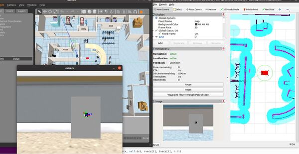
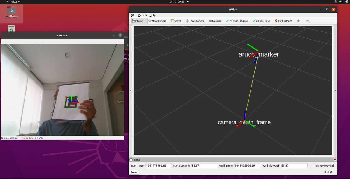
Here is the output:
You will notice that the pose of the ArUco marker tag jumps around inside RViz. The reason for this has to do with factors such as the amount of lighting, the camera resolution, and the calibration parameters. Small adjustments on these values can have a big impact.
That’s it! Keep building!