How to Assemble the QWinOut DIY Radio-Controlled Quadcopter

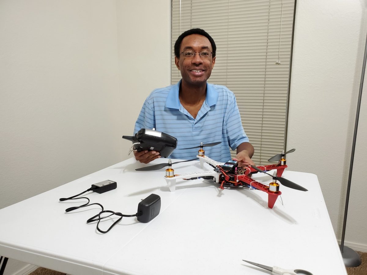
In this post, I’ll show you how to assemble the QWinOut DIY Radio Controlled Quadcopter (450mm).

Requirements

Here are the requirements:

  • Assemble the quadcopter by following the instructional video below.
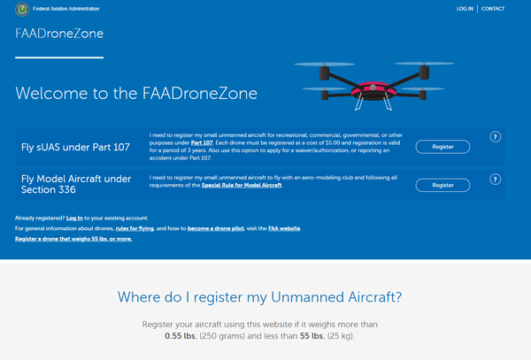
  • Register the drone with the Federal Aviation Administration (FAA).
  • Make a video of the flight.

Hardware Design

The following components are used in this system. They are all contained in the QWinout DIY Controlled Quadcopter Kit.
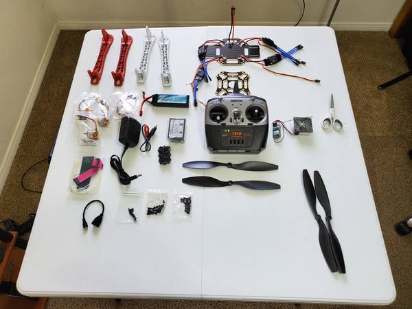
qwinout_quadcopter_parts_3

Spare Parts

Setup

Here are the steps for the hardware setup:

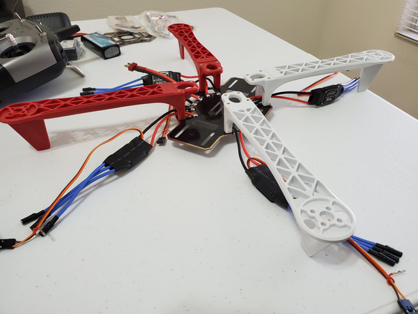
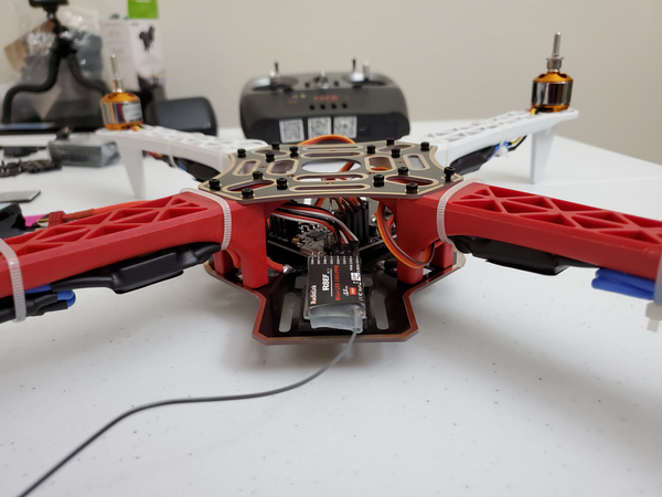
To begin, I secured the four plastic arms to the frame board with the screws. I used my fingers to tighten the screws, followed by a 5/64 in. long arm hex Allen key wrench.

qwinout_quadcopter_parts_2

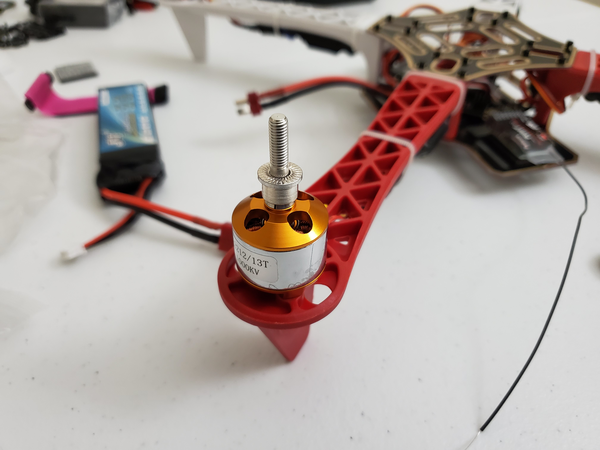
I secured the motor on the motor mount of the arm with the screws. I used my fingers to tighten the screws, followed by a 3/32 in. long arm hex Allen key wrench.

qwinout_quadcopter_parts_1

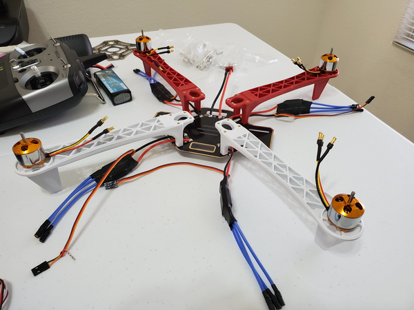
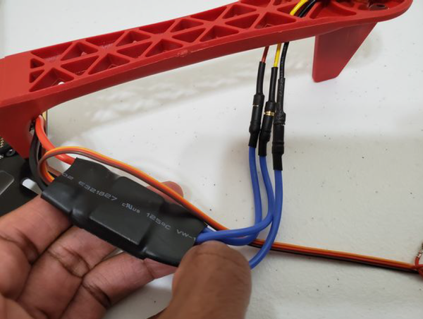
I connected all four motors to the four Electronic Speed Controllers (ESCs). Black to black, red to red, and yellow to the middle wire.

qwinout_450mm_quadcopter_assembly (2)

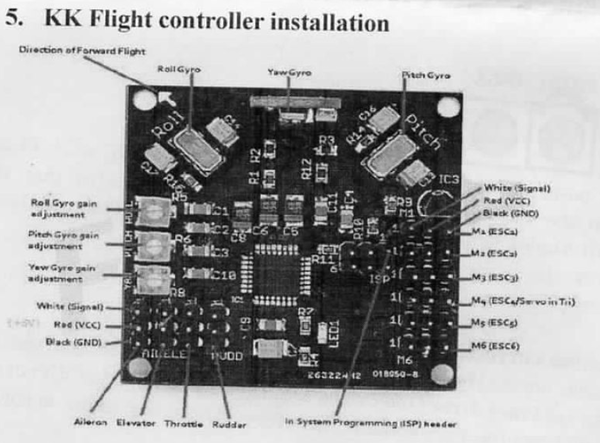
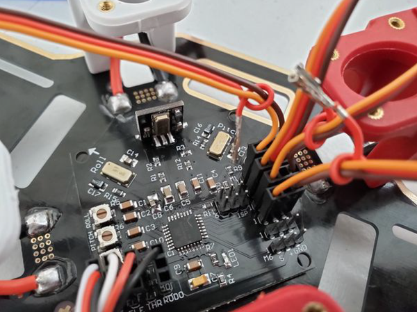
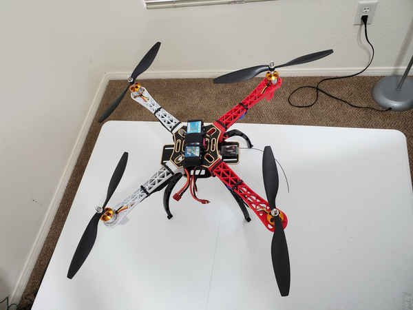
I installed the KK Flight Controller on the board with the adhesive tape. I then connected the flight controller M1-M4 ports to the ESCs according to the sequence below. The arrow on the flight controller points to the front of the quadcopter.

qwinout_450mm_quadcopter_assembly (3)

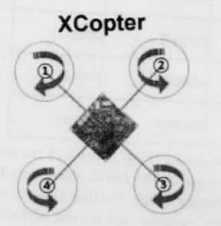
Below is the direction that each motor should spin. Two motors will spin counterclockwise, and two motors will spin clockwise.

motor_spin_direction
qwinout_450mm_quadcopter_assembly (5)

Next, I installed batteries in the back of the Radio Link remote control. I then turned it on.

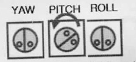
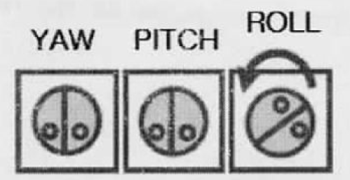
I then placed the aircraft horizontally. I turned off the PITCH knob switch by turning it counterclockwise. I used a 2.4mm flathead screwdriver to do this.

yaw_pitch_roll

I then connected the power of the aircraft. The flight controller light flashed quickly then slowly, indicating the neutral point signal was identified and saved. This completed the Transmitter Central Point Calibration.

I unplugged the power supply.

I turned on the PITCH knob by turning it clockwise 125 degrees.

I then did the Gyro direction correction. I turned off the ROLL knob switch by turning it counterclockwise.

yaw_pitch_roll_2

I then cut off the aircraft power supply. I turned the ROLL knob clockwise 125 degrees to turn it back on.

I then turned off the YAW knob by switching it counterclockwise all the way.

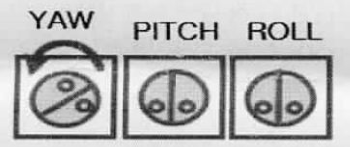
I pulled the throttle stick up to its highest position. I powered on the aircraft. I then pulled the remote control throttle back to its lowest point. This completed the calibration.

I turned the YAW knob switch clockwise 125 degrees to turn it back on.

Next, I unlocked the aircraft. I turned on the remote control, plugged in the quadcopter, and pushed the throttle stick (the button on the left) to the bottom right to unlock the aircraft.

I then checked the motor rotation direction to make sure motor 1 in the front left spun clockwise, motor 3 in the rear right spun clockwise, and the other two motors spun counterclockwise. To change the direction of a motor, I switched the black and yellow wires of motors 1 and 3 (any two of the three wires can be switched) because they were spinning counterclockwise.

Next, I secured the radio receiver behind the flight controller.

secure_radio_receiver

I then used the plastic cable ties to secure the ESC signal wires to the quadcopter.

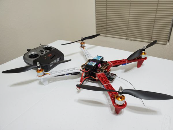
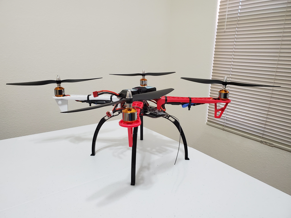
I then secured the other frame board and the 4 arm groups with the screws.
I then added the parts to secure the propeller. There are two propellers that spin clockwise, and two propellers that spin counterclockwise. This video here helped me to determine which blade is clockwise and which blade is counterclockwise.

propeller_parts

Lastly, with the quadcopter assembled, I followed the “How to Fly a Drone: A Beginner’s Guide”, and I registered my drone with the FAA.

register_drone_at_faa

Implementation

qwinout_450mm_quadcopter_assembly (4)
qwinout_450mm_quadcopter_assembly (6)
You can also add the skid gear legs which I have linked to in the “Spare Parts” section of this post (see above)
qwinout_450mm_quadcopter_assembly (1)

Video

Here is the video of my quadcopter in action:

How to Develop an Arduino-Based Optical Tachometer

In this post, I’ll explain how to develop an Arduino-Based Optical Tachometer that measures the speed of a brushless propeller. The speed of the propeller must be measured using an IR Emitter/Detector pair using either Round Robin with Interrupts or Function Queue Scheduling. The RPMs (revolutions per minute) must be captured over time, downloaded to a Host, and graphed.

If you have ever driven a car or looked at the dashboard of a car, you have seen a tachometer. It is that meter on the other side of your speedometer that measures the rotation speed of your engine’s crankshaft in revolutions per minute (RPM). A tachometer is an instrument that measures the rotation speed of a shaft or disk, such as in a motor.

tachometer

Requirements

Here are the requirements I created for this project:

  • The system must execute on an Arduino.
  • The speed of a brushless propeller must be measured using an Infrared (IR) Emitter/Detector pair
  • The speed of a brushless propeller must be measured using Round Robin with Interrupts.
  • The revolutions per minute (RPMs) must be captured over time.
  • The RPMs must be downloaded to a Host.
  • Time vs. RPMs must be graphed.

Hardware Design

The following components are used in this project. You will need:

Here is the diagram of the hardware setup:

hardware_diagram_optical_tachometer

For the motor setup on the left of the image above, the current (when the transistor is “turned on”) goes from the 5V power supply, through the green wire, through the motor, and then down the yellow wire. It then passes through the collector towards the emitter, and then down to ground. If the transistor is shut off, it is no longer conducting. The residual peak current that would normally go through the transistor from the yellow wire needs somewhere to go. Instead of being forced through the non-conducting transistor (and potentially damaging it), the current redirects (shorts through the motor) and dissipates through the diode (from left to right through the diode in the schematic above) since diodes only allow current to travel in one direction.

optical_tachometer_arduino (1)
optical_tachometer_arduino (2)
optical_tachometer_arduino (3)

Troubleshooting Tips

  • There might be occasions where you start the motor (after you run the code in the Implementation section below), and the RPM readings start firing even though the propeller is nowhere near the IR emitter/receiver pair. If this happens to you, power the propeller/motor from a separate breadboard and Arduino.
    • You will also need to take out the pieces of code from the code below that pertain to the operation of the motor and upload that code in a separate sketch to the other Arduino (the one that will power the propeller). It is a pain in the butt to do all this and can take several extra hours or so of development time, but it will help solve this problem.
  • It is also helpful to cover the propeller blades with black electrical tape in case the IR emitter beam is passing right through the propeller blades.

Implementation

Here is the source code that you will need to load to your Arduino:

/**
 * In this program, we develop an Arduino-Based Optical Tachometer 
 * that measures the speed of a brushless propeller.
 * 
 * The Infrared LED is connected to pin 13.
 * The Infrared Phototransistor is connected to pin 2 (interrupts).
 * 
 * @version 1.0 2019-02-18
 * @author Addison Sears-Collins
 */
 
// Assign a name to the DC motor pin on the Arduino Uno
const unsigned int MOTOR_PIN = 3;

// Assign a name to the infrared LED pin on the Arduino Uno
const unsigned int IR_LED = 13;

// The number of blades on the propeller. Adjust accordingly.
const unsigned int BLADE_COUNT = 3;

// Volatile keyword is used with interrupts
// This variable is subject to change inside an interrupt
// service routine
volatile unsigned int break_number = 0;

// Flag used to stop the program
bool done = false;

// Used for capturing the time
unsigned long time;

// Used for capturing the rpm (revolutions per minute)
unsigned int rpm;

/**
 *  Function runs only once, after each powerup or reset of the Arduino Uno
 */
void setup() {

  // Open the serial port and set the data transmission rate to 9600 bits 
  // per second. 9600 is the default baud rate for Arduino Uno.
  Serial.begin(9600);

  // Show a welcome message as human-readable ASCII text
  Serial.println("PROPELLER RPM PROGRAM");
  Serial.println("This program transmits the time and RPM of a propeller.");
  Serial.println("Created by Addison Sears-Collins");
  Serial.println("");
  Serial.println("Press ! to end the program");
  Serial.println("");
  Serial.println("Please enter the desired speed of the motor.");
  Serial.println("Must be a value between 100 and 255.");
  Serial.println("");
  Serial.println("TIME, RPM");

  // The Infrared phototransistor is connected to pin 2.
  // Interrupt triggers when signal goes from HIGH to LOW
  attachInterrupt(digitalPinToInterrupt(2), isr_break_count, FALLING); 

  // Turn on the IR Led
  pinMode(IR_LED, OUTPUT);
  digitalWrite(IR_LED, HIGH);

  // Enable output for the motor
  pinMode(MOTOR_PIN, OUTPUT);

  break_number = 0;
  rpm = 0;  
 
}

/**
 *  Main function
 */
void loop() {

  display_time_and_rpm();
  
  start_motor();

  while(!done) {    

    // Update time and rpm every second
    delay(1000);

    // Don't process interrupts during this calculation
    noInterrupts();

    // Calculate the RPM. If a 3-blade propeller, 3 breaks
    // per second would yield 1 rpm, which is 60 rpm. 
    rpm = (60 * break_number) / BLADE_COUNT;

    // Display the time and rpm
    display_time_and_rpm();

    // End program if sentinel is entered 
    end_program();    
    
    break_number = 0;
    rpm = 0;

    // Restart interrupts
    interrupts();
  }
  
  // Do nothing
  while (true) {}
}

/**
  * This function starts the motor
  */
void start_motor() {

  // Wait for the user to enter the speed of the motor
  while (Serial.available() == 0){};

  // Activate the motor
  int speed = Serial.parseInt();
  if (speed >= 100 && speed <= 255) {
    analogWrite(MOTOR_PIN, speed);
  }
}

/**
  * Interrupt service routine.
  * This function counts the number of interrupts
  */
void isr_break_count() {

  break_number++;
  
}

/**
  * Function displays the time and rpm
  */
void display_time_and_rpm() {
  
  // Capture the time and covert to seconds
  time = millis() / 1000;

  // Display the time
  Serial.print(time); 
  Serial.print(" , ");
  // Println so the next line begins on a new line
  // Display the rpm
  Serial.println(rpm);   
}

/**
  * This function ends the program
  */
void end_program() {
  
  // Used for reading data from the serial monitor
  char ch;

  // Check to see if ! is available to be read
  if (Serial.available()) {     
  
    // Read the character
    // Serial.read() returns the first (oldest) character in the buffer 
    // and removes that byte of data from the buffer
    ch = Serial.read();    

    // End the program if an exclamation point is entered in the
    // serial monitor
    if (ch == '!') {
      done = true;  

      // Turn off the motor
      analogWrite(MOTOR_PIN, 0);

      // Turn off the IR LED
      digitalWrite(IR_LED, LOW);
      
      Serial.println("Finished recording RPM. Goodbye.");
    }
  }    
}

rpm_vs_time_2

Video

How to Transmit Time and Temperature Using a TMP36 Sensor and Arduino

In this post, I’ll explain how to transmit time and temperature using a TMP36 sensor and an Arduino. The application that you will develop executes on an Arduino and transmits the time and temperature at a periodic rate of around 10 seconds across a Serial bus (e.g. USB) to a host computer (such as your personal laptop computer).

Requirements

Here are the requirements I created for this project:

  • The system must execute on an Arduino.
  • A temperature sensor connected to an Arduino must be calibrated.
  • The main program must use a Round Robin with interrupts design:
    • The temperature must be captured and converted to Fahrenheit.
    • The temperature must begin recording after the temperature has stabilized at room temperature.
    • The temperature must be recorded at a periodic rate of around 10 seconds (i.e. 10,000 milliseconds) at room temperature.
    • The temperature must then be recorded for 5 minutes at a periodic rate of around 10 seconds inside a refrigerator.
    • The temperature must then be recorded for 5 minutes at a periodic rate of around 10 seconds at room temperature.
  • The time and temperature must be transmitted across a Serial bus such as USB to my host.
  • The time and temperature data must be exported as a comma separated value file.
  • The comma separated value file must be read into a spreadsheet program (e.g. Microsoft Excel).
  • The temperature vs time must be plotted.

Hardware Design

The following components are used in this project. You will need:

Here is the diagram of the TMP36 temperature sensor:

tmp36_sensor_diagram

Here is the diagram of the hardware setup:

tmp36

Here are the steps for setting up the hardware of the Serial Transmit of Temperature system:

  • Step 1. Place the TMP36 sensor on the breadboard. Each lead of the sensor will be on a different rail section of the breadboard.
  • Step 2. Connect a jumper wire between the ground lead of the TMP36 sensor and the – rail of the breadboard.
  • Step 3. Connect a jumper wire between the – rail of the breadboard and the GND pin of the Arduino.
  • Step 4. Connect a jumper wire between the 5V pin of the Arduino and the + rail of the breadboard.
  • Step 5. Connect a jumper wire between + rail of the breadboard and the 5V lead of the TMP36 sensor.
  • Step 6. Connect a jumper wire between the middle output lead of the TMP36 sensor and the Analog 0 pin of the Arduino.
tmp36_sensor

Here are the steps for calibrating the TMP36 sensor:

We will use the One Point Calibration technique using a known temperature, 32°F, which is the freezing point of water.

  1. Crush several ice cubes and place in a plastic bag with some distilled water (Ada 2015).
  2. Close the bag up, making sure it is tied tight.
  3. Make sure the bag is completely dry on the outside and place it on top of the TMP36 sensor.
  4. Adjust temperature accordingly to calibrate.

Implementation

Here is the source code that you will need to load to your Arduino:

#include <TimerOne.h>
// This TimerOne.h library handles time-based interrupts

/**
 * In this program, we develop an application which executes on an Arduino 
 * and transmits the time and temperature at a periodic rate of around 10 
 * seconds across a Serial bus (USB) to the Host.
 * 
 * Uses the timer interrupts technique discussed on page 270 in 
 * "Exploring Arduino: Tools and Techniques for Engineering Wizardry" 
 * by Jeremy Blum
 * 
 * @version 7.0 2019-02-14
 * @author Addison Sears-Collins
 */
 
// Assign a name to the TMP36 sensor pin on the Arduino Uno
const unsigned int TEMP_SENSOR_PIN = A0;

// Flag used to stop the program
bool done = false;

// Used for capturing the time
unsigned long time;

// Used for capturing the temperature in Fahrenheit
float temp_fahrenheit;

/**
 *  Function runs only once, after each powerup or reset of the Arduino Uno
 */
void setup() {
  
  // Open the serial port and set the data transmission rate to 9600 bits 
  // per second. 9600 is the default baud rate for Arduino Uno.
  Serial.begin(9600); 
  
  // Show a welcome message as human-readable ASCII text
  Serial.println("SERIAL TRASMIT OF TEMPERATURE PROGRAM");
  Serial.println("This program transmits the time and temperature at a periodic");
  Serial.println("rate of ~10 seconds across a Serial bus (USB) to the Host.");
  Serial.println("Created by Addison Sears-Collins");
  Serial.println("");
  Serial.println("Press ! to end the program");
  Serial.println("");
  Serial.println("Recording temperature every 10 seconds...");
  Serial.println("");
  Serial.println("TIME, TEMPERATURE IN DEGREES FAHRENHEIT");

  // Interrupt: Set a timer of length 10000000 microseconds (10 seconds)
  Timer1.initialize(10000000);

  //Runs "isr_read_temperature" on each timer interrupt
  Timer1.attachInterrupt(isr_read_temperature); 
 
}

/**
 *  Main function
 */
void loop() {

  // Wait 100 seconds for temperature to stabilize
  // Temperature is being read in the background
  // via the interrupts
  delay(100000);

  while(!done) {    

    // Display the time and temperature
    display_time_and_temperature();
  
    // End program if sentinel is entered 
    end_program();    

    // Display time and temperature every 10 seconds
    delay(10000);
  }
  
  // Do nothing
  while (true) {}
}

/**
  * This function is the interrupt service routine.
  * It reads the voltage and converts to degrees Fahrenheit
  */
void isr_read_temperature() {
  
  // Read the voltage of the TMP36 sensor
  int sensor_voltage = analogRead(TEMP_SENSOR_PIN);
  
  // Calibrated. Equation taken from datasheet.
  // http://kookye.com/wp-content/uploads/samplecode/tempsensor.txt
  temp_fahrenheit = 5.1 + ((125 * sensor_voltage) >> 8);
}

/**
  * Function displays the time and temperature
  */
void display_time_and_temperature() {
  
  // Capture the time and covert to seconds
  time = millis() / 1000;

  // Display the time
  Serial.print(time); 
  Serial.print(" , ");
  // Println so the next line begins on a new line
  // Display the temperature in Fahrenheit
  Serial.println(temp_fahrenheit);   
}

/**
  * This function ends the program
  */
void end_program() {
  
  // Used for reading data from the serial monitor
  char ch;

  // Check to see if ! is available to be read
  if (Serial.available()) {     
  
    // Read the character
    // Serial.read() returns the first (oldest) character in the buffer 
    // and removes that byte of data from the buffer
    ch = Serial.read();    

    // End the program if an exclamation point is entered in the
    // serial monitor
    if (ch == '!') {
      done = true;  
      Serial.println("Finished recording temperature. Goodbye.");
    }
  }    
}

temperature_vs_time_tmp36_sensor
Graph of Temperature vs Time

Video