In this tutorial, we will build a robotic arm with a vacuum suction cup that can enable you to pick up items in one location and place them in another.
Our goal is to build an early prototype of a product that can make it easier and faster for factories and warehouses to do their work.
Real-World Applications
Robotic arm systems have a number of real-world applications. Here are just a few examples:
- Warehouses and Logistics (the largest market for this kind of robot):
- Picking items off shelves and placing them into boxes for shipping (e.g. IAM Robotics, Order fulfillment at Amazon, Covariant.ai’s pick and place robot – see below, Nomagic’s robot).
- Stacking boxes (e.g. Boston Dynamics)
- Automated storage and retrieval of items.
- Removing defective products off conveyor belts (i.e. quality control).
- Grocery Stores
- Grocery picking and packing system using computer vision (e.g. British online supermarket, Ocado).
- Restocking shelves.
- Hospitals and Medical Centers (the second largest market for professional service robots):
- Perform ultrasounds, take mouth swabs, and listen to sounds made by a patient’s organs in order to prevent frontline medical professionals from getting infected (e.g. Beijing’s Tsinghua Changgung Hospital).
- Military
- Food Processing Plants
- Here is a link to a YouTube video of a sandwich factory that processes 3 million sandwiches every week.
Not only do robotic arms help solve labor shortages, but they also help increase productivity when they work alongside humans. In this video from The Wall Street Journal, you can see how robotic arms working side-by-side with humans can enhance productivity.
We will build an early prototype of the products you see above. Let’s get started!
Prerequisites
- You have the Arduino IDE (Integrated Development Environment) installed on your PC (Windows, MacOS, or Linux).
- You have experience controlling multiple motors using Arduino (helpful but not required).
You Will Need
This section is the complete list of components you will need for this project:
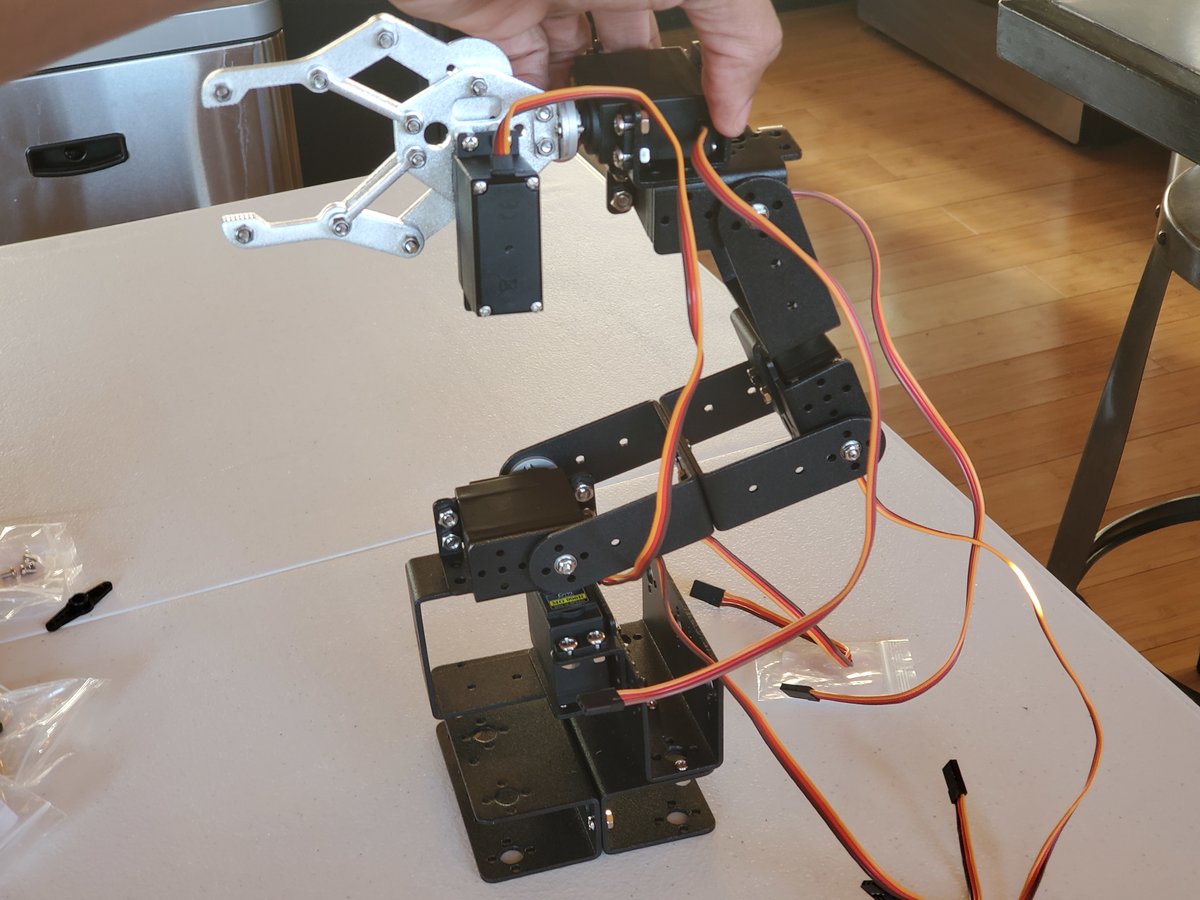
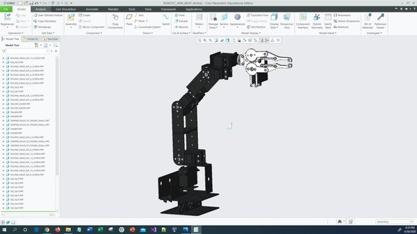
Robot Arm Kit (Assembled) – Go to ebay and type “Air Pump Robotic Arm Kit” or go to Aliexpress and type “Robotic arm vacuum suction pump”
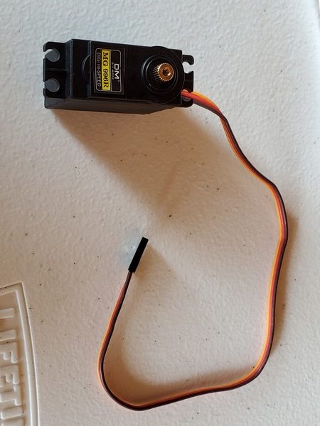
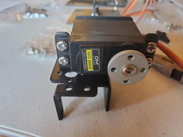
- 2 x KS-3620 180° Servo (Suitable Voltage: 4.8 – 6.6V; No-load Current: 80-100mA)
- 1 x KS-3620 270° Servo (Suitable Voltage: 4.8 – 6.6V; No-load Current: 80-100mA)
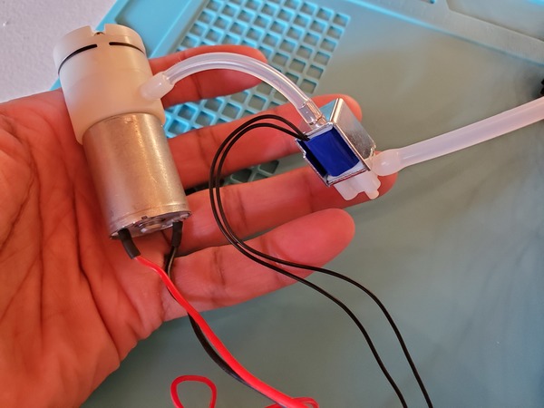
- 1 x Micro Air (Vacuum) Pump (Suitable Voltage: 3.7V – 6V; Rated current: <0.4A)
- 1 x Solenoid Valve – Electrically controlled valve that opens up and lets air through when it receives the proper voltage – (Suitable Voltage 3V – 6V; Rated current: 0.14A)
- 1 x Silicone Tubing Hose (2mm inner diameter)
Robot Suction Cup Vacuum Pump Kit For 25T (i.e. 25 Teeth Servo Spline) Servos (check ebay or Aliexpress)
- 1 x Set of Silicone Suction Cup (Dual)
- 2 x PWM Electronic Switches
- 1 x Vacuum Pump
- 1 x 800mm Silicone Hose
- 1 x Tee-Joint Electronic Valve (also known as Solenoid Valve)
Extra Components You’ll Need
- 1 x Arduino Mega 2560 Rev 3 (Recommended Voltage: 7V – 12V, Voltage Range: 6-20V)
- 3 x 10K Ohm Potentiometer with Knobs
- 2 x On Off Mini Rocker Switch
- 1 x Momentary Push Button Switch
- 1 x 9V Battery Clip with 2.1 x 5.5 mm Male DC Power Plug
- 1 x 9V Battery (to plug into the Arduino board)
- 1 x 3m Length Food Grade Translucent Silicone Tubing Hose 2mm ID x 4mm OD
- 3 in 1 Jumper Wires
- 2 x 400-Point Solderless Breadboards (Stick two of them together to create a large breadboard)
- Alligator Clip to Male and Female Jumper Wires
- 1 x DC Adjustable Power Supply Capable of 30V/10A (This will power everything but the Arduino and potentiometers…you could also use a 4 x AA Battery Holder With Wires or a 6V, 2800mAh, NiMH Battery Pack. Just be aware that these batteries will drain really quickly).
- 2 x C Shape Desk Table Mount Clamp (to secure the arm to a table)
- Fender Washers 18-8 Stainless Steel Large Diameter Washers – Size: 1/2 in. Inner Diameter x 2 in. Outer Diameter (search on ebay)
- 1x Force-Sensitive Resistor
- 1 x 10k Ohm Resistor
- 1 x Heat Insulation Silicone Repair Mat
- 1 x 40-Watt Soldering Station
- 1 x 63-37 Tin Lead Rosin core solder wire
- 1 x Damp sponge
- 1 x Roll of Scotch Tape
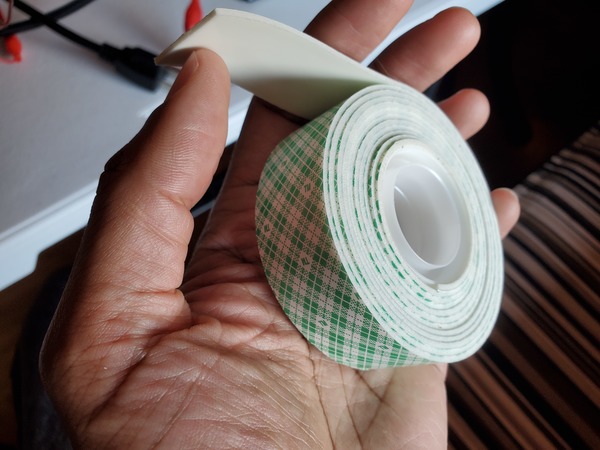
- 1 x Roll of Scotch Permanent Mounting Tape, 1 Inch x 125 Inches
- 1 x Spiral Wire Wrap (Optional. For organizing the wires.)
- 1 x Acrylonitrile Butadiene Styrene (ABS) Plastic Dustproof Waterproof Box (Optional. I won’t use this in this project, but you would use this to house all the electronics.)
- 1 x Cordless Power Drill Set (Optional. To drill holes in the waterproof box).
Getting Started
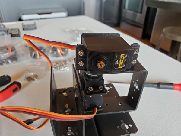
Test the Servo Motors
The first thing we need to do is to test the three servo motors.
Here is the wiring diagram in pdf format.
We need to power the servo motors with an external power supply because they draw a lot of current…so much current that it would damage your Arduino Mega if you were to connect the power leads directly.
Here are two different programs you can use to test. The first program enables you to control the position of the servos directly using the potentiometers. The second program sweeps each motor back and forth.
When you launch these programs on the robot, I recommend you turn on the external power first. Then plug the 9V battery into the Arduino.
/*
Program: Control 3 Servos Using Arduino and Potentiometers
File: control_3_servos_with_potentiometer_varspeedservolib.ino
Description: Turn the knob of the potentiometers
             to control the angle of the 3 servos.
             This program enables you to control the speed of the servos
             as well.
Author: Addison Sears-Collins
Website: https://automaticaddison.com
Date: July 10, 2020
*/

#include <VarSpeedServo.h>

// Define the number of servos
#define SERVOS 3

// Create the servo objects.
VarSpeedServo myservo[SERVOS];

// Speed of the servo motors
// Speed=1: Slowest
// Speed=255: Fastest.
const int desired_speed = 255;

// Attach servos to digital pins on the Arduino
int servo_pins[SERVOS] = {3,5,6};

// Analog pins used to connect the potentiometers
int potpins[SERVOS] = {A0,A1,A2};

// Variables to read the value from the analog pin
int potpin_val[SERVOS];

void setup() {

  for(int i = 0; i < SERVOS; i++) {

    // Attach the servos to the servo object
    // attach(pin, min, max  ) - Attaches to a pin
    // setting min and max values in microseconds
    // default min is 544, max is 2400
    myservo[i].attach(servo_pins[i], 544, 2400);
  }
}

void loop() {

  // Update servo position
  for(int i = 0; i < SERVOS; i++) {
    potpin_val[i] = analogRead(potpins[i]);
    potpin_val[i] = map(potpin_val[i], 0, 1023, 0, 180);
    myservo[i].write(potpin_val[i], desired_speed, true);
  }
}
/*
Program: Control 3 Servos Using Arduino and Sensor Shield v5.0
File: move_3_servo_motors_to_angle.ino
Description: Move servo motors to a specific angle
Author: Addison Sears-Collins
Website: https://automaticaddison.com
Date: July 10, 2020
*/

#include <VarSpeedServo.h>

// Define the number of servos
#define SERVOS 3

// Create the servo objects.
VarSpeedServo myservo[SERVOS];

// Speed of the servo motors
// Speed=1: Slowest
// Speed=255: Fastest.
const int desired_speed = 25;

// Attach servos to digital pins on the Arduino
int servo_pins[SERVOS] = {3,5,6};

void setup() {

  for(int i = 0; i < SERVOS; i++) {

    // Attach the servos to the servo object
    myservo[i].attach(servo_pins[i]);
  }
}

void loop() {

  // Move each servo back and forth
  for(int i = 0; i < SERVOS; i++) {
    myservo[i].write(60, desired_speed, true);
    myservo[i].write(120, desired_speed, true);
    myservo[i].write(60, desired_speed, true);
    delay(250);
  }
  delay(250);
}
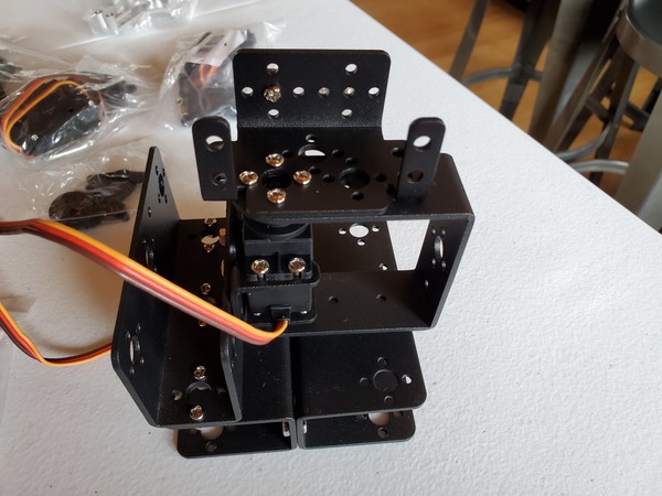
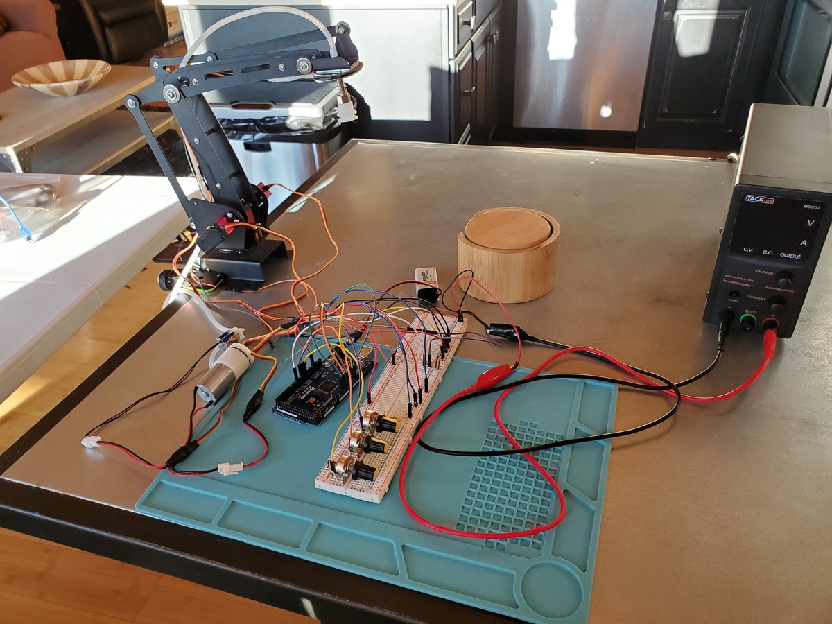
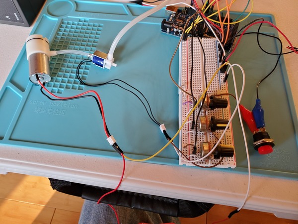
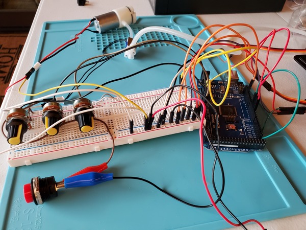
Connect the Components
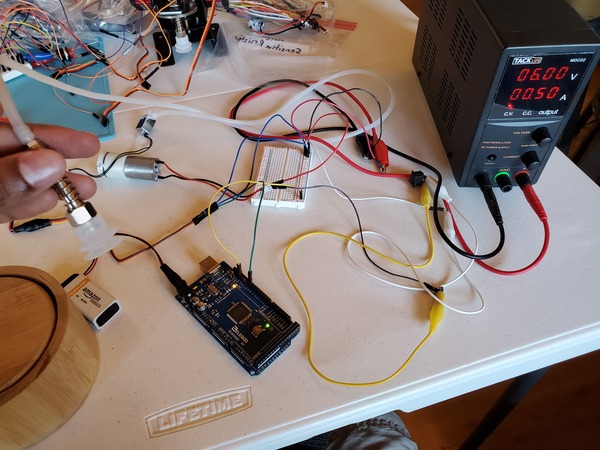
Now that you’ve tested the motors, it is time to connect everything else.
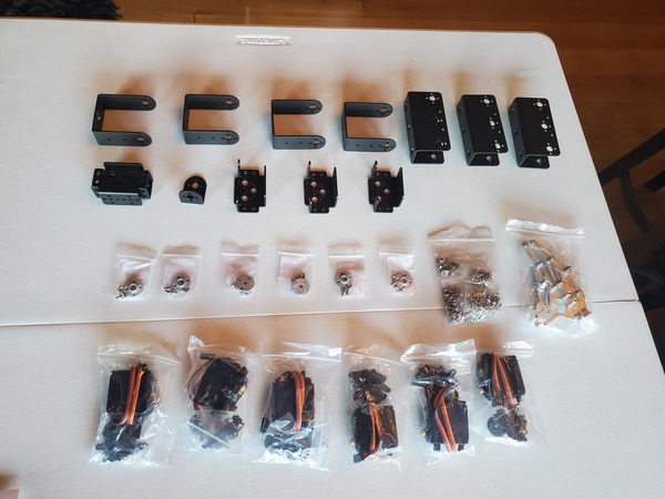
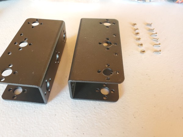
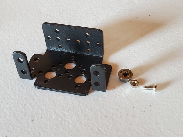
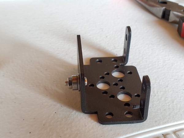
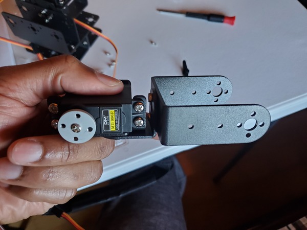
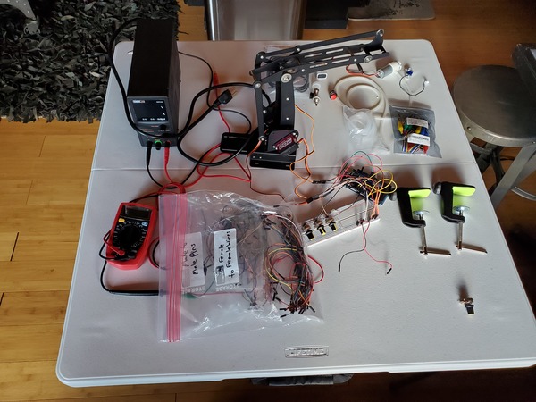
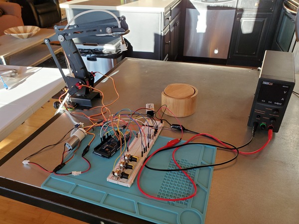
Get all the components that you need to build this project, and lay them out on a table. Now is a good time to double check that you have everything you need.
Wire up all the components. You can use either this diagram or this diagram depending on your preference.
I suggest downloading the wiring diagram and then zooming in so you can see everything.
Don’t be intimidated by all the connections. Just go one part and one wire at a time. Take it slowly so that you wire everything up correctly.
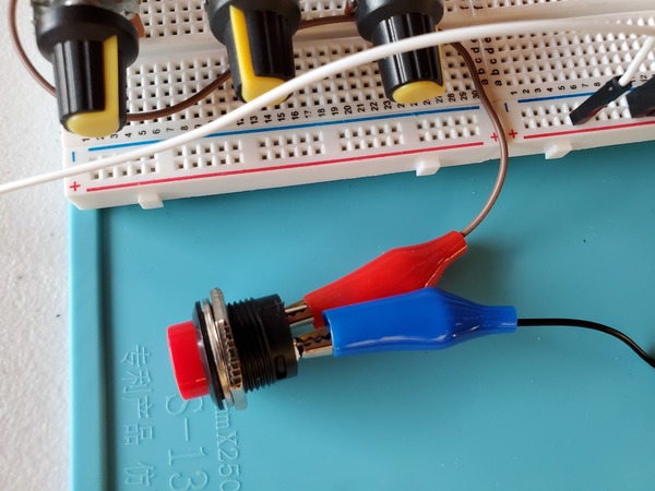
For the two solenoid wires and the momentary push button switch, it doesn’t matter which one is Ground and which one is VCC (i.e. positive voltage).
Launch Manual Suction Control
We will control our robot manually using the three potentiometers. Load the control_3_servos_with_potentiometer_varspeedservolib.ino program (you made earlier) to your Arduino.
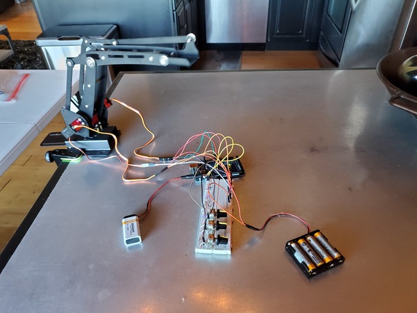
Now plug in everything so that your program is running. The power supply I’m using is 6V for the voltage with a 3A current limit.
You may notice in the beginning that the servos jump a bit when you first launch the program. That’s totally normal.
In a real-world setting, you would want to consider programming the robot so that you can press a button and return the servos to the home position before you shut it down. Then, when you restart the program, the robotic arm will initialize in the home position. This way, you won’t have an arm flying around when you launch the arm.
Using the potentiometers to control the angles of the servos, move the suction cup to a specific object you want to pick up.
When the suction cup reaches the object, push and hold down quickly on the object in order to pick it up.
Then move the servos to your desired drop location.
When ready, release the suction by pushing the momentary push button switch.
Launch Automatic Suction Control
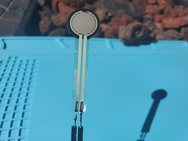
We will now use a force sensitive resistor to control when to deactivate suction. A force sensitive resistor detects physical pressure, squeezing, and weight.
We will use this resistor to automatically detect when the suction cup has made contact with an object. This component will therefore help us automate the process of picking and placing an object.
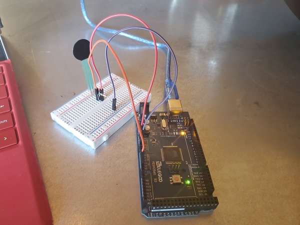
Test the Force Sensitive Resistor
Let’s begin by writing a small program to test the force sensitive resistor.
Here is the wiring diagram in pdf format.
Here is the code. I saved the file as test_force_sensitive_resistor.ino:
/* FSR simple testing sketch.
Connect one end of FSR to power, the other end to Analog 5.
Then connect one end of a 10K resistor from Analog 5 to ground
For more information see www.ladyada.net/learn/sensors/fsr.html */
int fsrPin = A5; // the FSR and 10K pulldown are connected to A5
int fsrReading; // the analog reading from the FSR resistor divider
void setup(void) {
// We'll send debugging information via the Serial monitor
Serial.begin(9600);
}
void loop(void) {
fsrReading = analogRead(fsrPin);
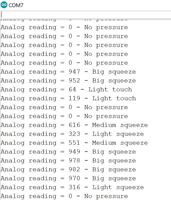
Serial.print("Analog reading = ");
Serial.print(fsrReading); // the raw analog reading
// We'll have a few threshholds, qualitatively determined
if (fsrReading < 10) {
Serial.println(" - No pressure");
} else if (fsrReading < 200) {
Serial.println(" - Light touch");
} else if (fsrReading < 500) {
Serial.println(" - Light squeeze");
} else if (fsrReading < 800) {
Serial.println(" - Medium squeeze");
} else {
Serial.println(" - Big squeeze");
}
delay(200);
}
For a full description of the force sensitive resistor, check out this post on Adafruit.com.
Load the code to your Arduino.
With your USB still plugged in, run the code, and open the Serial Monitor in the Arduino IDE. You will need to click the green magnifying glass in the upper-right of the IDE.
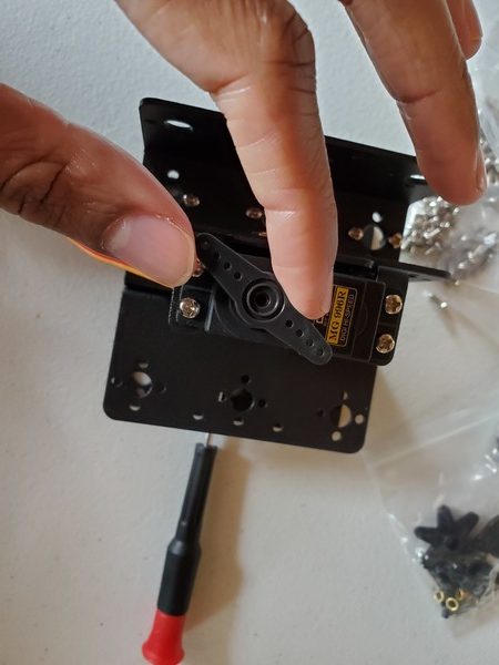
Press the round part of the force sensitive resistor with your finger, and observe the output on the Serial Monitor.
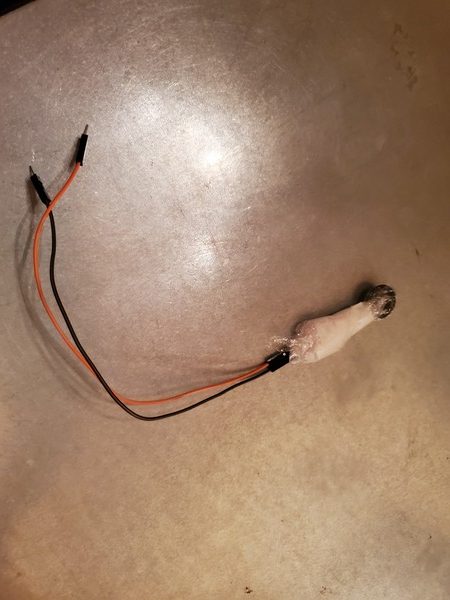
I highly recommend soldering the Force Sensitive Resistor to male-to-male solder wires.
If you’ve never soldered before, there are a ton of good YouTube videos on how to do it. You can also check this link where I did some soldering for a robotic car.
Install the Force Sensitive Resistor on the Robot
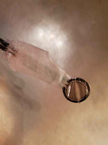
Cover the head (round part) of the force sensitive resistor in order to protect it. I used some cling wrap and tape to protect it.
Secure the cling wrap over the force sensitive resistor using some scotch tape.
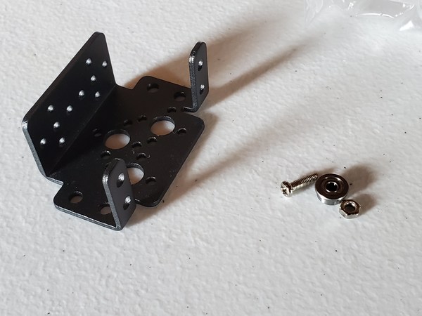
Now grab one of the big washers (with 1/2 in. inner diameter and 2 in. outer diameter).
Cut some small pieces of Scotch permanent mounting tape, and place it around the hole.
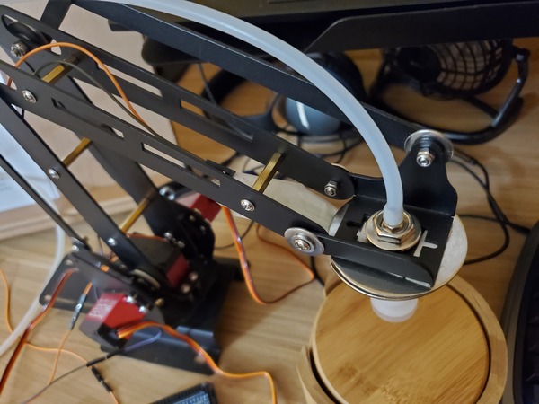
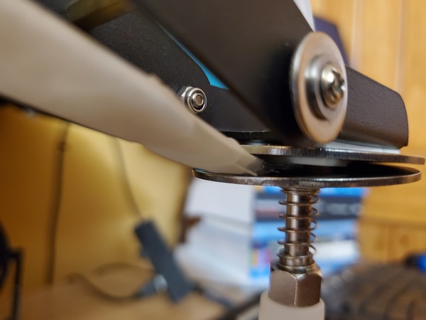
Slide the washer over the tube until it sits on top of the nut above the suction cup.
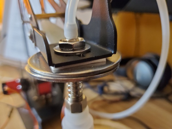
Now grab the other big washer (with 1/2 in. inner diameter and 2 in. outer diameter).
Tape it to the end-effector of the robotic arm using Scotch permanent mounting tape.
Grab the force sensitive resistor and tape it to the big washer that is attached to the robotic arm (i.e. the upper washer). The two wires should flow out through the back of the robotic arm.
The front of the force sensitive resistor should face upward right against the tape.
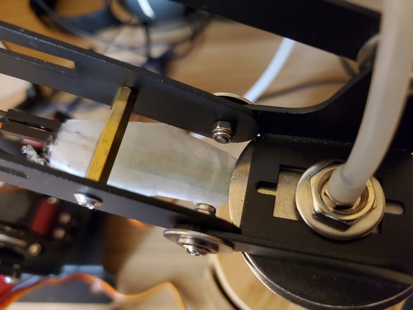
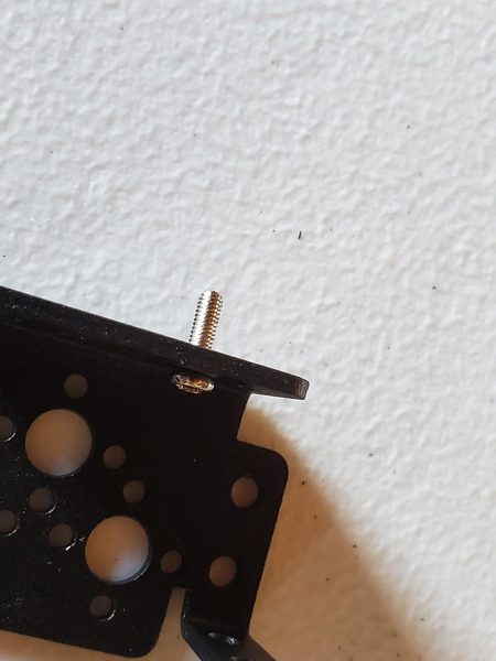
Take the tube and thread it through the hole in the robotic arm.
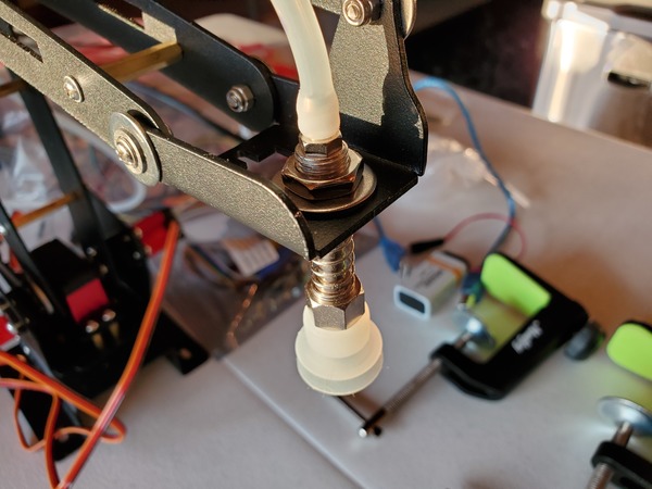
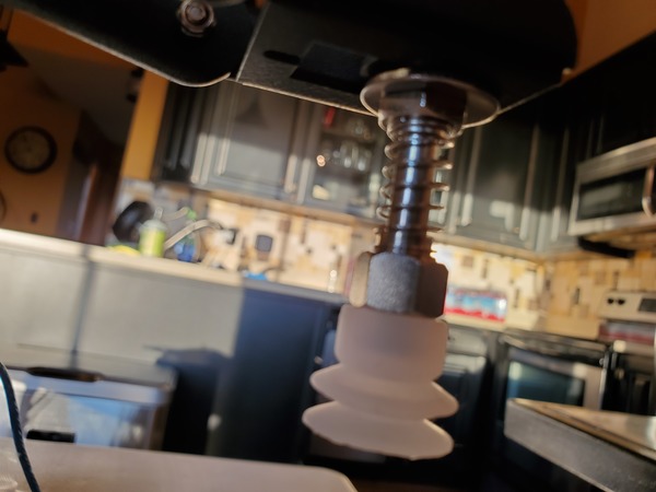
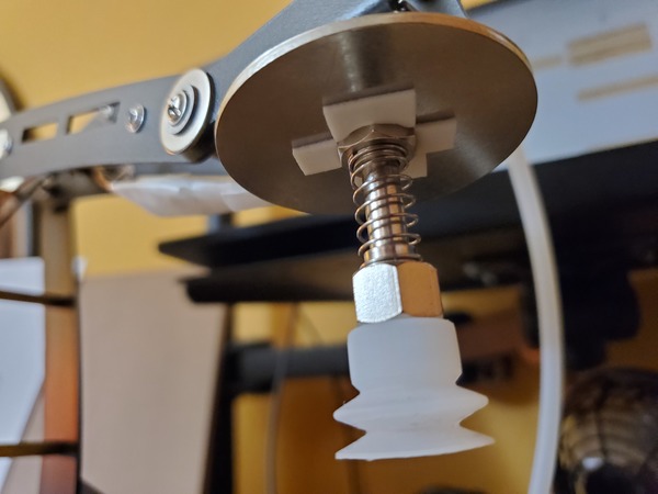
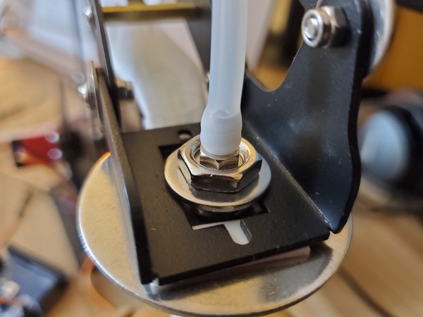
Place a washer and then a nut down over the tube so that both sit on top of the end effector.
Using your fingers, secure the nut on top of the washer. Do not secure it tightly…just enough so that it isn’t loose (We’ll come back to this screw in the next section)
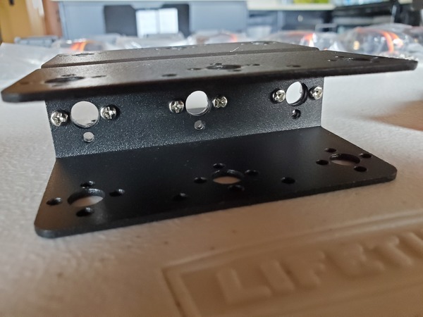
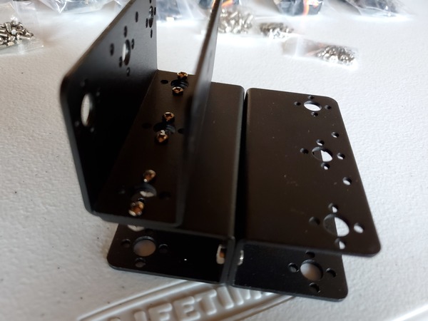
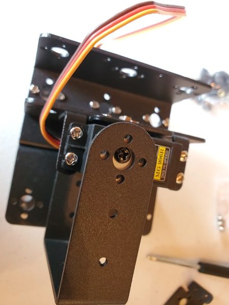
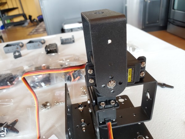
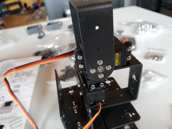
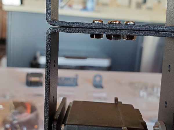
Pictures are worth 1000 words, so here is how the setup should look when you’re done.
Calibrate the Robotic Arm With Force Sensitive Resistor
Now, we need to adjust the nut that sits on top of the end effector to the appropriate tightness.
Connect the force sensitive resistor according to the wiring diagram here in pdf format.
Load test_force_sensitive_resistor.ino to your Arduino.
With your USB still plugged in, run the code, and open the Serial Monitor in the Arduino IDE. You will need to click the green magnifying glass in the upper-right of the IDE.
You should see the reading “no pressure” on your Serial Monitor.
Tighten the nut until you see a reading of “Light touch,” “Light squeeze,” or “Medium squeeze.”
Now, loosen the nut until you see the first reading of “No pressure”.
To test to see if everything is working properly, with your hand (no need to turn on the motors), guide the robotic arm towards an object.
Press the suction cup down on an object and then pull it off the object.
- Each time you press the suction cup down on an object you should see either “Light touch,” “Light squeeze,” “Medium squeeze,” or “Big squeeze.”
- When the suction cup isn’t touching anything, you should see “No pressure.”
Once you’ve got 1 and 2 above, your robotic arm with force sensitive resistor is calibrated properly.
Have patience. It takes a while to secure the nut to just the right tightness. You want it not too tight but not too loose.
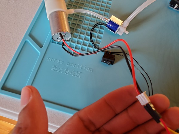
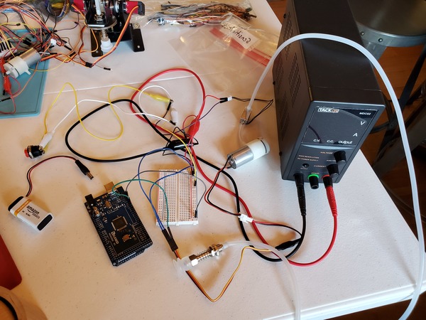
Test the Solenoid Valve With PWM Electronic Switch
Let’s test our solenoid valve to see if it is working properly. You will need to wire everything up like you see in this diagram.
If you are using a DC variable power supply, like I am, set it for 0.5A for the current limit and 6V for the voltage.
Where did I get 0.5A from? I know the current ratings for the vacuum pump and the solenoid, so I’m considering a 0.3A max for the vacuum pump and 0.2A max for the solenoid so that I don’t destroy them by allowing too much current to flow through them.
Now, write the following code and upload it to your Arduino. This code makes the vacuum suction cup turn ON for five seconds and then turn OFF for five seconds.
/*
Program: Test Solenoid Valve With PWM Electronic Switch
File: test_solenoid_valve.ino
Description: This program tests a solenoid valve
  with electronic switch to see if it is working
  properly.
Author: Addison Sears-Collins
Website: https://automaticaddison.com
Date: July 29, 2020
*/

#include <VarSpeedServo.h>

// Create a solenoid valve control object
VarSpeedServo my_solenoid_valve;

// Attach solenoid to digital pin on the arduino
int solenoid_pin = 9;

void setup() {
  // Attach the solenoid to the solenoid valve control object
  my_solenoid_valve.attach(solenoid_pin);

  // We assume the vacuum pump is turned ON
  // When the vacuum pump is ON, and the solenoid valve OFF:
  // --Suction is ON
  // When the vacuum pump is ON, and the solenoid valve ON:
  // --Suction is OFF
  // Start with solenoid valve OFF (0 is OFF, 180 is ON)
  my_solenoid_valve.write(0);
}

// The vacuum suction cup turns ON for five seconds and then
// turns OFF for five seconds.
void loop() {
  my_solenoid_valve.write(0); // Turn the solenoid valve OFF (Suction is ON)
  delay(5000); // Wait five seconds
  my_solenoid_valve.write(180); // Turn the solenoid valve OFF (Suction is OFF)
  delay(5000); // Wait five seconds

}
Test the Vacuum Pump With PWM Electronic Switch
Let’s test our vacuum pump to see if it is working properly. You will need to wire everything up like you see in this diagram.
If you are using a DC variable power supply, like I am, set it for 0.5A for the current limit and 6V for the voltage.
Now, write the following code and upload it to your Arduino. This code makes the vacuum suction cup turn ON for five seconds and then turn OFF for five seconds.
/*
Program: Test Vacuum Pump With PWM Electronic Switch
File: test_vacuum_pump.ino
Description: This program tests a vacuum pump
  with electronic switch to see if it is working
  properly.
Author: Addison Sears-Collins
Website: https://automaticaddison.com
Date: July 29, 2020
*/

#include <VarSpeedServo.h>

// Create a vacuum pump control object
VarSpeedServo my_vacuum_pump;

// Attach vacuump pump to digital pin on the arduino
int vacuum_pump_pin = 10;

void setup() {
  // Attach the vacuum pump to the vacuum pump control object
  my_vacuum_pump.attach(vacuum_pump_pin);

  // Start with vacuum pump ON (0 is OFF, 180 is ON)
  my_vacuum_pump.write(180);
}

// The vacuum suction cup turns ON for five seconds and then
// turns OFF for five seconds.
void loop() {
  my_vacuum_pump.write(180); // Turn the vacuum pump ON (Suction is ON)
  delay(5000); // Wait five seconds
  my_vacuum_pump.write(0); // Turn the vacuum pump OFF (Suction is OFF)
  delay(5000); // Wait five seconds

}
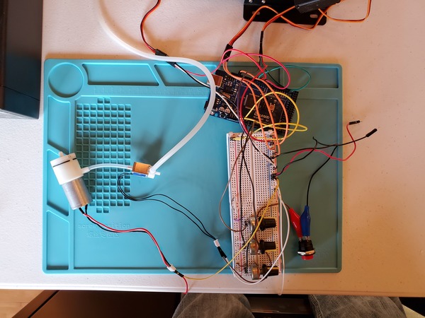
Test the Vacuum Pump and Solenoid Valve With PWM Electronic Switches
Let’s test our vacuum pump and solenoid valve together to see if they work properly as a unit. You will need to wire everything up like you see in this diagram.
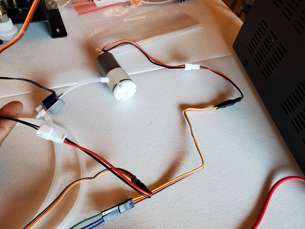
If you are using a DC variable power supply, like I am, set it for 0.5A for the current limit and 6V for the voltage.
Now, write the following code and upload it to your Arduino. This code makes the vacuum suction cup turn ON for five seconds and then turn OFF for five seconds.
/*
Program: Test Vacuum Pump and Solenoid Valve With PWM Electronic Switches
File: test_vacuum_pump_and_solenoid.ino
Description: This program tests the vacuum pump and solenoid valve
  together to see if they work properly as a unit.
Author: Addison Sears-Collins
Website: https://automaticaddison.com
Date: July 29, 2020
*/

#include <VarSpeedServo.h>

// Create a solenoid valve control object
VarSpeedServo my_solenoid_valve;

// Create a vacuum pump control object
VarSpeedServo my_vacuum_pump;

// Attach solenoid to digital pin on the arduino
int solenoid_pin = 9;

// Attach vacuump pump to digital pin on the arduino
int vacuum_pump_pin = 10;

void setup() {
  // Attach the solenoid to the solenoid valve control object
  my_solenoid_valve.attach(solenoid_pin);

  // Attach the vacuum pump to the vacuum pump control object
  my_vacuum_pump.attach(vacuum_pump_pin);

  // We assume the vacuum pump is turned ON
  // When the vacuum pump is ON, and the solenoid valve OFF:
  // --Suction is ON
  // When the vacuum pump is OFF, and the solenoid valve ON:
  // --Suction is OFF
  // Start with vacuum pump ON (0 is OFF, 180 is ON)
  my_vacuum_pump.write(180);
  // Start with solenoid valve OFF (0 is OFF, 180 is ON)
  my_solenoid_valve.write(0);
}

// The vacuum suction cup turns ON for five seconds and then
// turns OFF for five seconds.
void loop() {

  // Suction is ON
  my_solenoid_valve.write(0);
  my_vacuum_pump.write(180);

  delay(5000); // Wait five seconds

  // Suction is OFF
  my_solenoid_valve.write(180);
  my_vacuum_pump.write(0);

  delay(5000); // Wait five seconds
}
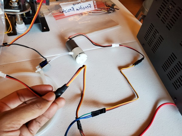
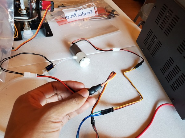
Test Force Sensitive Resistor With Vacuum Pump and Solenoid Valve
Let’s add our force sensitive resistor to our setup.
You will need to wire everything up like you see in this diagram.
If you are using a DC variable power supply, like I am, set it for 0.5A for the current limit and 6V for the voltage.
Now, write the following code and upload it to your Arduino. This code runs in two stages:
- Stage 0 (Pick up object)
- Starts with the suction turned OFF (i.e. vacuum is OFF and solenoid is ON)
- Gives you time to move the robotic arm in position so that the vacuum suction cup is touching the object you want to pick up.
- Checks to see if the vacuum suction cup is touching the object you want to pick up.
- If the vacuum suction cup is touching the object you want to pick up, suction is turned ON (i.e. vacuum is switched ON and solenoid is switched OFF).
- Stage 1 (Place object)
- Gives you time to move the robotic arm in position to place the object in your desired location.
- Suction is turned OFF, and the object is released.
/*
Program: Test Force Sensitive Resistor With Vacuum Pump and Solenoid Valve
File: test_vacuum_solenoid_force_sensor.ino
Description: This program tests the vacuum pump, solenoid valve, and
  force sensitive resistor to see if they work properly as a unit.

  Connect one end of FSR to power, the other end to Analog 5.
  Then connect one end of a 10K resistor from Analog 5 to ground.
Author: Addison Sears-Collins
Website: https://automaticaddison.com
Date: July 29, 2020
*/

#include <VarSpeedServo.h>

// Create a solenoid valve control object
VarSpeedServo my_solenoid_valve;

// Create a vacuum pump control object
VarSpeedServo my_vacuum_pump;

// Attach solenoid to digital pin on the arduino
int solenoid_pin = 9;

// Attach vacuum pump to digital pin on the arduino
int vacuum_pump_pin = 10;

int fsrPin = A5;     // the FSR and 10K pulldown are connected to A5
int fsrReading = 0;     // the analog reading from the FSR resistor divider
int stage = 0; // Keep track of the stage we are in

void setup() {

  // Attach the solenoid to the solenoid valve control object
  my_solenoid_valve.attach(solenoid_pin);

  // Attach the vacuum pump to the vacuum pump control object
  my_vacuum_pump.attach(vacuum_pump_pin);

  // When the vacuum pump is ON, and the solenoid valve OFF:
  // --Suction is ON
  // When the vacuum pump is OFF, and the solenoid valve ON:
  // --Suction is OFF
  // Start with Suction OFF
  my_solenoid_valve.write(180); // 0 is OFF, 180 is ON
  my_vacuum_pump.write(0); // 0 is OFF, 180 is ON
}

void loop() {

  /* Stage 0 - Pick up an object */
  while(stage == 0) {

    // Check to see if contact has been made with an object
    fsrReading = analogRead(fsrPin);
    fsrReading += analogRead(fsrPin);
    fsrReading += analogRead(fsrPin);
    fsrReading = fsrReading / 3;
    if (fsrReading > 300) {
      // Suction is ON
      my_solenoid_valve.write(0);
      my_vacuum_pump.write(180);
      stage = 1;
    }
  }

  // Move the robotic arm into position to place the object.
  // Delay is in milliseconds. Change this value as you see fit.
  delay(3000);

  /* Stage 1 - Place an object */
  // Suction is OFF
  my_solenoid_valve.write(180);
  my_vacuum_pump.write(0);
  stage = 0;
}
Putting It All Together for Pick and Place
Now, to finish off all this, let’s add the servo motors so that we can control the robotic arm with the potentiometers.
You will need to wire everything up like you see in this diagram.
If you are using a DC variable power supply, like I am, set it for 3.5A for the current limit and 6V for the voltage.
Now, write the following code and upload it to your Arduino. Control the robotic arm using the three potentiometers. The code is similar to the code from the last section with just a few new lines of code.
/*
Program: Robot With Vacuum Pump and Automatic Suction Control
File: automatic_suction_control.ino
Description: This program uses a vacuum pump, solenoid valve, and
  force sensitive resistor to create automatic suction control.

  Connect one end of FSR to power, the other end to Analog 5.
  Then connect one end of a 10K resistor from Analog 5 to ground.
Author: Addison Sears-Collins
Website: https://automaticaddison.com
Date: July 30, 2020
*/

#include <VarSpeedServo.h>

/********************** SERVOS ***********************/
// Define the number of servos
#define SERVOS 3

// Create the servo objects.
VarSpeedServo myservo[SERVOS];

// Speed of the servo motors
// Speed=1: Slowest
// Speed=255: Fastest.
const int desired_speed = 255;

// Attach servos to digital pins on the Arduino
int servo_pins[SERVOS] = {3,5,6};

// Analog pins used to connect the potentiometers
int potpins[SERVOS] = {A0,A1,A2};

// Variables to read the value from the analog pin
int potpin_val[SERVOS];

/****************** SOLENOID VALVE *******************/

// Create a solenoid valve control object
VarSpeedServo my_solenoid_valve;

// Attach solenoid to digital pin on the arduino
int solenoid_pin = 9;

/******************* VACUUM PUMP *********************/

// Create a vacuum pump control object
VarSpeedServo my_vacuum_pump;

// Attach vacuum pump to digital pin on the arduino
int vacuum_pump_pin = 10;

/*************** FORCE SENSITIVE RESISTOR *************/

int fsrPin = A5;     // the FSR and 10K pulldown are connected to A5
int fsrReading = 0;     // the analog reading from the FSR resistor divider
int stage = 0; // Keep track of the stage we are in

void setup() {

  // Set up servos
  for(int i = 0; i < SERVOS; i++) {

    // Attach the servos to the servo object
    // attach(pin, min, max  ) - Attaches to a pin
    // setting min and max values in microseconds
    // default min is 544, max is 2400
    myservo[i].attach(servo_pins[i], 544, 2400);
  }

  // Attach the solenoid to the solenoid valve control object
  my_solenoid_valve.attach(solenoid_pin);

  // Attach the vacuum pump to the vacuum pump control object
  my_vacuum_pump.attach(vacuum_pump_pin);

  // When the vacuum pump is ON, and the solenoid valve OFF:
  // --Suction is ON
  // When the vacuum pump is OFF, and the solenoid valve ON:
  // --Suction is OFF
  // Start with Suction OFF
  my_solenoid_valve.write(180); // 0 is OFF, 180 is ON
  my_vacuum_pump.write(0); // 0 is OFF, 180 is ON

}

void loop() {

  /* Stage 0 - Pick up an object */
  while(stage == 0) {

    // Move the robotic arm into position to pick up the object
    // Modify the number of time steps as you see fit.
    for(int j = 0; j < 50; j++) {

      // Update servo position
      for(int i = 0; i < SERVOS; i++) {
        potpin_val[i] = analogRead(potpins[i]);
        potpin_val[i] = map(potpin_val[i], 0, 1023, 0, 180);
        myservo[i].write(potpin_val[i], desired_speed, true);
      }
    }

    // Check to see if contact has been made with an object
    fsrReading = analogRead(fsrPin);
    fsrReading += analogRead(fsrPin);
    fsrReading += analogRead(fsrPin);
    fsrReading = fsrReading / 3;
    if (fsrReading > 300) {
      // Suction is ON
      my_solenoid_valve.write(0);
      my_vacuum_pump.write(180);
      stage = 1;
    }
  }

  // Move the robotic arm into position to place the object
  // Modify the number of time steps as you see fit.
  for(int j = 0; j < 3000; j++) {

    // Update servo position
    for(int i = 0; i < SERVOS; i++) {
      potpin_val[i] = analogRead(potpins[i]);
      potpin_val[i] = map(potpin_val[i], 0, 1023, 0, 180);
      myservo[i].write(potpin_val[i], desired_speed, true);
    }
  }

  /* Stage 1 - Place an object */
  // Suction is OFF
  my_solenoid_valve.write(180);
  my_vacuum_pump.write(0);
  stage = 0;
}