In this tutorial, I’ll show you how to set up two-way communication between your Raspberry Pi and your Arduino. I’ve done something similar in the past, but let’s take a look at a simpler example.
Here is our end goal:
- We will send a block of integers from the Raspberry Pi to the Arduino.
- We will then have the Arduino repeat those integers back to the Raspberry Pi.
- The Raspberry Pi will then print the integers it received from the Arduino.
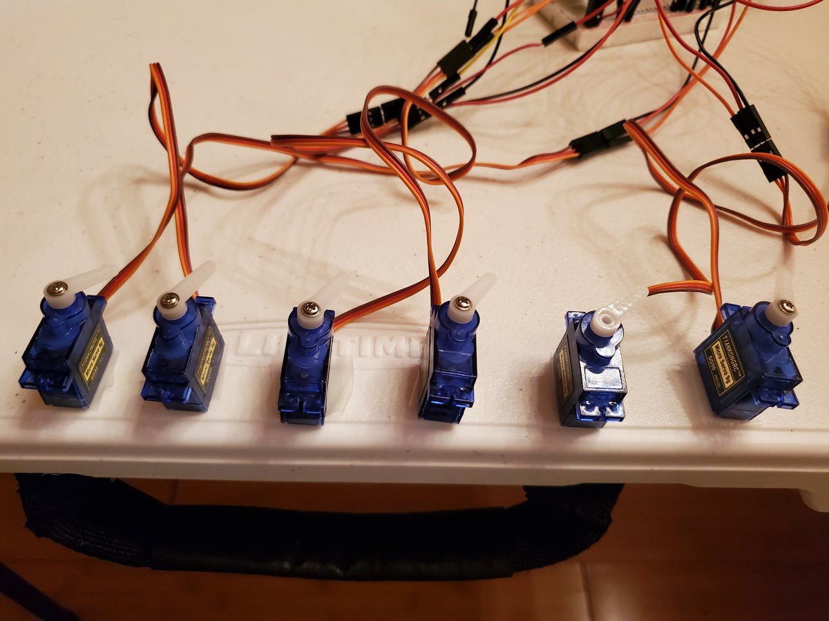
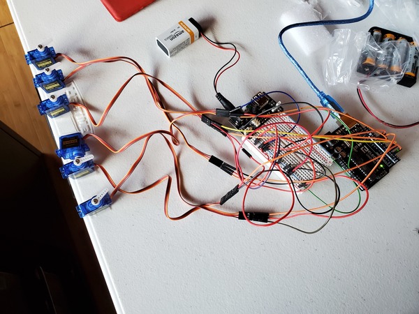
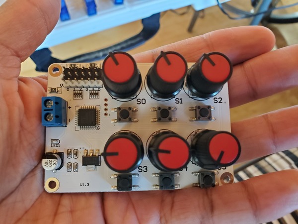
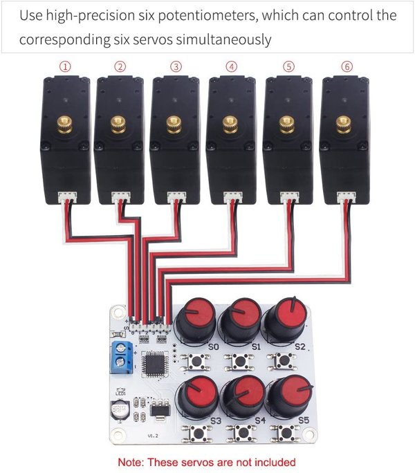
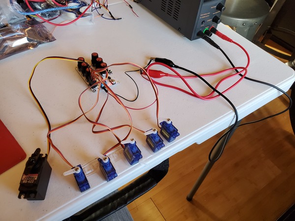
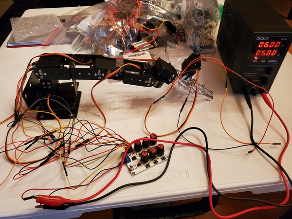
A real-world application of two-way communication between Raspberry Pi and Arduino is when you have a robotic arm that needs to pick up an object from a conveyor belt in a warehouse (or factory) and place that object inside a bin. This task is commonly known as pick and place.
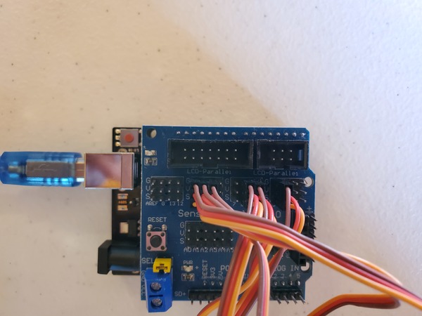
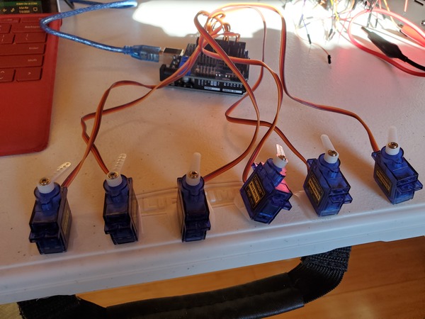
A camera is mounted above the robotic arm. You want to have the Raspberry Pi detect and recognize objects via the camera (using computer vision software like OpenCV), do some calculations, and then send servo angle values to the Arduino. The Arduino will then move the servo motors accordingly so the robotic arm can pick up the object.
Prerequisites
- You have the Arduino IDE (Integrated Development Environment) installed either on your personal computer or on your Raspberry Pi. I’m using Arduino Uno.
- You have Raspberry Pi set up. (Raspberry Pi 3B, 3B+, 4, etc…doesn’t matter which one)
Directions
Send a String From Arduino to Raspberry Pi
Let’s get started by sending a string of text (“Hello World”) from your Arduino to your Raspberry Pi.
Write the following program and upload it to your Arduino. Save it as send_string_to_raspberrypi.ino.
/*
Program: Send Strings to Raspberry Pi
File: send_string_to_raspberrypi.ino
Description: Send strings from Arduino to a Raspberry Pi
Author: Addison Sears-Collins
Website: https://automaticaddison.com
Date: July 5, 2020
*/
void setup(){
// Set the baud rate
Serial.begin(9600);
}
void loop(){
// Print "Hello World" every second
// We do println to add a new line character '\n' at the end
// of the string.
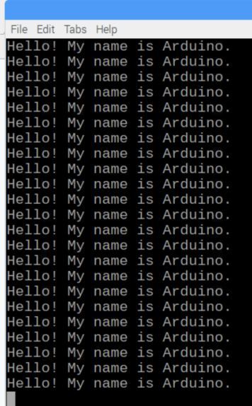
Serial.println("Hello! My name is Arduino.");
delay(1000);
}
Before you connect the Arduino to your Raspberry Pi, you need to set up the Raspberry Pi so that it can receive data from the Arduino. We first need to figure out the port that connects the Arduino and the Raspberry Pi.
Turn on your Raspberry Pi, and open a new terminal window.
Update the list of packages on your system:
sudo apt-get update
Upgrade any outdated packages (optional):
sudo apt-get upgrade
Install the PySerial package.
python3 -m pip install pyserial
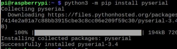
If you get an error, you need to install pip first. After you run the command below, then try installing PySerial again.
sudo apt install python3-pip
Open a new terminal window, and type the following command to get a list of all the ports that begin with the prefix tty.
ls /dev/tty*
Here is what you should see:
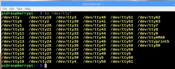
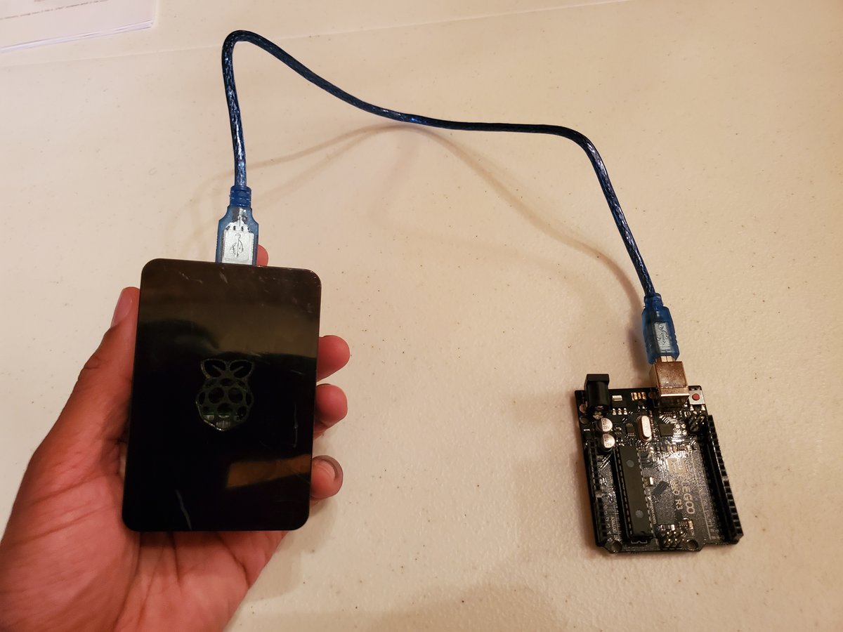
Now, plug the USB (Universal Serial Bus) cable into your Arduino and connect that to the USB port of your Raspberry Pi.
Reboot your computer.
sudo reboot
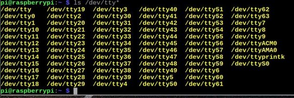
Once you’ve rebooted the computer, type the command again in the terminal window on your Raspberry Pi:
ls /dev/tty*
You see the new port? You should see a new port with a name like /dev/ttyACM0. That is your Arduino.
Another way to see all the USB devices connected to your Raspberry Pi is to use this command:
lsusb
Set the baud rate of that port (i.e. the speed of data communication over that port/channel). Let’s use 9600. 9600 isn’t set in stone. For other projects you could use 38400, 57600, 115200, etc.
stty -F /dev/ttyACM0 9600
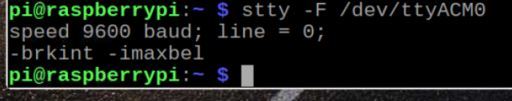
Let’s check the baud rate to see if it is set properly.
stty -F /dev/ttyACM0
Now, create a new folder that will store the code we are going to write.
cd Documents
mkdir pi_arduino_communication
Move inside that folder.
cd pi_arduino_communication
Install gedit, my favorite text editor.
sudo apt-get install gedit
Create a new Python program.
gedit receive_string_from_arduino.py
Write the following code and save it.
#!/usr/bin/env python3

###############################################################################
# Program: Receive Strings From an Arduino
# File: receive_string_from_arduino.py
# Description: This program runs on a Raspberry Pi. It receives a string from
#  Arduino and prints that string to the screen.
# Author: Addison Sears-Collins
# Website: https://automaticaddison.com
# Date: July 5, 2020
###############################################################################

import serial # Module needed for serial communication

# Set the port name and the baud rate. This baud rate should match the
# baud rate set on the Arduino.
# Timeout parameter makes sure that program doesn't get stuck if data isn't
# being received. After 1 second, the function will return with whatever data
# it has. The readline() function will only wait 1 second for a complete line
# of input.
ser = serial.Serial('/dev/ttyACM0', 9600, timeout=1)

# Get rid of garbage/incomplete data
ser.flush()

# Infinite loop
while (1):

  # If there is data available
  if(ser.in_waiting > 0):

    # Read everything until the new line character
    # Convert the data from a byte into a string of type 'utf-8'
    # You could also use 'ascii'
    # rstrip() function removes trailing characters like
    # the new line character '\n'
    line = ser.readline().decode('utf-8').rstrip()

    # Print the data received from the Arduino
    print(line)
Make it executable.
chmod +x receive_string_from_arduino.py
Now run the program.
./receive_string_from_arduino.py
You should see this print out to your screen.
When you’re ready, press CTRL+C to stop the Python script.
Send a String From Raspberry Pi to Arduino
In this section, we will:
- Create a Python program that sends a string from the Raspberry Pi to the Arduino
- The Arduino will respond back to the Raspberry Pi with the string it has received.
- The Raspberry Pi will print out the string it received from the Arduino.
Let’s start by creating the program for the Arduino.
Create the following sketch, and upload it to your Arduino. Save it as receive_string_from_raspberrypi.ino.
/*
Program: Receive Strings From Raspberry Pi
File: receive_string_from_raspberrypi.ino
Description: Receive strings from a Raspberry Pi
Author: Addison Sears-Collins
Website: https://automaticaddison.com
Date: July 5, 2020
*/
void setup(){
// Set the baud rate
Serial.begin(9600);
}
void loop(){
if(Serial.available() > 0) {
String data = Serial.readStringUntil('\n');
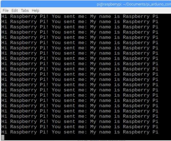
Serial.print("Hi Raspberry Pi! You sent me: ");
Serial.println(data);
}
}
Now go over to your Raspberry Pi, and open a new Python file.
Open a new terminal window, and type the following commands:
cd Documents/pi_arduino_communication
gedit send_strings_to_arduino.py
Write the following code and save it.
#!/usr/bin/env python3

###############################################################################
# Program: Send Strings to an Arduino From a Raspberry Pi
# File: send_strings_to_arduino.py
# Description: This program runs on a Raspberry Pi. It sends strings
#   to Arduino. It also receives the  string it sent
#   and prints it to the screen. This provides bi-directional (2-way) communication
#   between Arduino and Raspberry Pi.
# Author: Addison Sears-Collins
# Website: https://automaticaddison.com
# Date: July 5, 2020
###############################################################################

import serial # Module needed for serial communication
import time # Module needed to add delays in the code

# Set the port name and the baud rate. This baud rate should match the
# baud rate set on the Arduino.
# Timeout parameter makes sure that program doesn't get stuck if data isn't
# being received. After 1 second, the function will return with whatever data
# it has. The readline() function will only wait 1 second for a complete line
# of input.
ser = serial.Serial('/dev/ttyACM0', 9600, timeout=1)

# Get rid of garbage/incomplete data
ser.flush()

# Infinite loop
while (1):

  send_string = ("My name is Raspberry Pi\n")

  # Send the string. Make sure you encode it before you send it to the Arduino.
  ser.write(send_string.encode('utf-8'))

  # Do nothing for 500 milliseconds (0.5 seconds)
  time.sleep(0.5)

  # Receive data from the Arduino
  receive_string = ser.readline().decode('utf-8').rstrip()

  # Print the data received from Arduino to the terminal
  print(receive_string)
Make it executable.
chmod +x send_strings_to_arduino.py
Plug your Arduino into your Raspberry Pi using the USB cable.
Now run the Python program.
./send_strings_to_arduino.py
You should see this print out to your screen.
Press CTRL+C when you’re done.
Send Integers From Arduino to Raspberry Pi
Let’s create programs to send integers from Arduino to Raspberry Pi.
Upload the following code to your Arduino. Save the file as send_ints_to_raspberrypi.ino.
/*
Program: Send Integers to Raspberry Pi
File: send_ints_to_raspberrypi.ino
Description: Send integers from Arduino to a Raspberry Pi
Author: Addison Sears-Collins
Website: https://automaticaddison.com
Date: July 5, 2020
*/

// Initialize the variables with some randomly-chosen integers
// that could represent servo motor angles, for example.
int servo_0_angle = 90;
int servo_1_angle = 7;
int servo_2_angle = 63;
int servo_3_angle = 85;
int servo_4_angle = 162;
int servo_5_angle = 45;

void setup(){

  // Set the baud rate
  Serial.begin(9600);

}

void loop(){

  // Print integers every 500 milliseconds
  // We do println to add a new line character '\n' at the end
  // of the comma-separated stream of integers
  Serial.print(servo_0_angle); Serial.print(",");
  Serial.print(servo_1_angle); Serial.print(",");
  Serial.print(servo_2_angle); Serial.print(",");
  Serial.print(servo_3_angle); Serial.print(",");
  Serial.print(servo_4_angle); Serial.print(",");
  Serial.println(servo_5_angle);
  delay(500);
}
Now go over to your Raspberry Pi.
Open a new terminal and go to your folder.
cd Documents/pi_arduino_communication
Create a new Python program.
gedit receive_ints_from_arduino.py
Write the following code and save it.
#!/usr/bin/env python3
###############################################################################
# Program: Receive Integers From an Arduino
# File: receive_ints_from_arduino.py
# Description: This program runs on a Raspberry Pi. It receives comma-separated
# integers from Arduino and prints them to the screen.
# Author: Addison Sears-Collins
# Website: https://automaticaddison.com
# Date: July 5, 2020
###############################################################################
import serial # Module needed for serial communication
# Set the port name and the baud rate. This baud rate should match the
# baud rate set on the Arduino.
# Timeout parameter makes sure that program doesn't get stuck if data isn't
# being received. After 1 second, the function will return with whatever data
# it has. The readline() function will only wait 1 second for a complete line
# of input.
ser = serial.Serial('/dev/ttyACM0', 9600, timeout=1)
# Initialize 6 integers
servo_0_angle = 90
servo_1_angle = 90
servo_2_angle = 90
servo_3_angle = 90
servo_4_angle = 90
servo_5_angle = 90
# Infinite loop
while (1):
# Read everything until the new line character
# Convert the data from a byte into a string of type 'utf-8'
# You could also use 'ascii'
line = ser.readline().decode('utf-8')
# Take out the commas. Parse the string into a list.
parsed = line.split(',')
# rstrip() function removes trailing characters like
# the new line character '\n' and '/r'. Also removes
# white space.
parsed = [x.rstrip() for x in parsed]
# We know we need to receive 6 integers. This code helps with any loss
# of data that might happen as data is transferred between Arduino
# and the Raspberry Pi.
if(len(parsed) > 5):
print(parsed)
# We add the '0' character to the end of each item in the
# parsed list. This makes sure that there are no empty
# strings in the list. Adding 0 makes sure that we have
# at least 6 string values we can convert into integers.
# Dividing by 10 removes the trailing 0 but it makes the integer a float.
# We then have to convert the float to an integer.
servo_0_angle = int(int(parsed[0]+'0')/10)
servo_1_angle = int(int(parsed[1]+'0')/10)
servo_2_angle = int(int(parsed[2]+'0')/10)
servo_3_angle = int(int(parsed[3]+'0')/10)
servo_4_angle = int(int(parsed[4]+'0')/10)
servo_5_angle = int(int(parsed[5]+'0')/10)
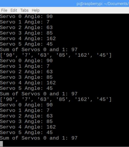
print("Servo 0 Angle: " + str(servo_0_angle))
print("Servo 1 Angle: " + str(servo_1_angle))
print("Servo 2 Angle: " + str(servo_2_angle))
print("Servo 3 Angle: " + str(servo_3_angle))
print("Servo 4 Angle: " + str(servo_4_angle))
print("Servo 5 Angle: " + str(servo_5_angle))
# This line proves that we have successfully converted the strings
# to integers.
print("Sum of Servos 0 and 1: " + str(servo_0_angle + servo_1_angle))
Make it executable.
chmod +x receive_ints_from_arduino.py
Plug your Arduino into your Raspberry Pi using the USB cable.
Now run the Python program.
./receive_ints_from_arduino.py
You should see this print out to your screen.
Send Integers From Raspberry Pi to Arduino
Let’s put it all together. We will:
- Create a Python program that sends integers from the Raspberry Pi to the Arduino.
- The Arduino will respond back to the Raspberry Pi with the integers it has received.
- The Raspberry Pi will print out the integers it received from the Arduino.
Let’s start by creating the program for the Arduino.
Create the following sketch, and upload it to your Arduino. Save it as receive_ints_from_raspberrypi.ino.
/*
Program: Receive Integers From Raspberry Pi
File: receive_ints_from_raspberrypi.ino
Description: Receive integers from a Raspberry Pi
Author: Addison Sears-Collins
Website: https://automaticaddison.com
Date: July 5, 2020
*/
// Initialize the integer variables
int servo_0_angle = 90;
int servo_1_angle = 90;
int servo_2_angle = 90;
int servo_3_angle = 90;
int servo_4_angle = 90;
int servo_5_angle = 90;
int sum = 0;
void setup(){
// Set the baud rate
Serial.begin(9600);
}
void loop(){
if(Serial.available() > 0) {
servo_0_angle = Serial.parseInt();
servo_1_angle = Serial.parseInt();
servo_2_angle = Serial.parseInt();
servo_3_angle = Serial.parseInt();
servo_4_angle = Serial.parseInt();
servo_5_angle = Serial.parseInt();
// Compute a sum to prove we have integers
sum = servo_0_angle + servo_1_angle;
// We do println to add a new line character '\n' at the end
// of the comma-separated stream of integers
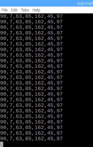
Serial.print(servo_0_angle); Serial.print(",");
Serial.print(servo_1_angle); Serial.print(",");
Serial.print(servo_2_angle); Serial.print(",");
Serial.print(servo_3_angle); Serial.print(",");
Serial.print(servo_4_angle); Serial.print(",");
Serial.print(servo_5_angle); Serial.print(",");
Serial.println(sum);
}
}
Now go over to your Raspberry Pi, and open a new Python file.
gedit send_ints_to_arduino.py
Write the following code and save it.
#!/usr/bin/env python3

###############################################################################
# Program: Send Integers to an Arduino From a Raspberry Pi
# File: send_ints_to_arduino.py
# Description: This program runs on a Raspberry Pi. It sends integers
#   to Arduino in comma-separated format. It also receives the integers it sent
#   and prints them to the screen. This provides bi-directional (2-way) communication
#   between Arduino and Raspberry Pi.
# Author: Addison Sears-Collins
# Website: https://automaticaddison.com
# Date: July 5, 2020
###############################################################################

import serial # Module needed for serial communication
import time # Module needed to add delays in the code

# Set the port name and the baud rate. This baud rate should match the
# baud rate set on the Arduino.
# Timeout parameter makes sure that program doesn't get stuck if data isn't
# being received. After 1 second, the function will return with whatever data
# it has. The readline() function will only wait 1 second for a complete line
# of input.
ser = serial.Serial('/dev/ttyACM0', 9600, timeout=1)

# Intialize the integer values we'll send to Arduino
servo_0_angle = 90
servo_1_angle = 7
servo_2_angle = 63
servo_3_angle = 85
servo_4_angle = 162
servo_5_angle = 45

# Get rid of garbage/incomplete data
ser.flush()

# Infinite loop
while (1):

  # Convert the integers to a comma-separated string
  angle_value_list = [str(servo_0_angle),str(servo_1_angle),str(
    servo_2_angle),str(servo_3_angle),str(servo_4_angle),str(servo_5_angle)]
  send_string = ','.join(angle_value_list)
  send_string += "\n"

  # Send the string. Make sure you encode it before you send it to the Arduino.
  ser.write(send_string.encode('utf-8'))

  # Receive data from the Arduino
  receive_string = ser.readline().decode('utf-8', 'replace').rstrip()

  # Print the data received from Arduino to the terminal
  print(receive_string)
Make it executable.
chmod +x send_ints_to_arduino.py
Plug your Arduino into your Raspberry Pi using the USB cable.
Now run the Python program.
./send_ints_to_arduino.py
You should see this print out to your screen.
Note that instead of receive_ints_from_raspberrypi.ino, you can use this code (receive_ints_from_raspberrypi_strings.ino). It is a bit more complicated (and takes up almost double the amount of memory), but the output is exactly the same. This is to show you that there are many ways to skin the cat:
/*
Program: Receive Integers From Raspberry Pi
File: receive_ints_from_raspberrypi_strings.ino
Description: Receive integers from a Raspberry Pi
Author: Addison Sears-Collins
Website: https://automaticaddison.com
Date: July 5, 2020
*/

// Initialize the integer variables
int servo_0_angle = 90;
int servo_1_angle = 90;
int servo_2_angle = 90;
int servo_3_angle = 90;
int servo_4_angle = 90;
int servo_5_angle = 90;

// Initialize the String variables
String servo_0_angle_str = "";
String servo_1_angle_str = "";
String servo_2_angle_str = "";
String servo_3_angle_str = "";
String servo_4_angle_str = "";
String servo_5_angle_str = "";

int sum = 0;

// Get ready to accept comma-separated values
int comma_position;

void setup(){

  // Set the baud rate
  Serial.begin(9600);

}

void loop(){

  if(Serial.available() > 0) {

    // Read string until the new line character
    String data = Serial.readStringUntil('\n');

    // There are 6 integers we will be receiving from the
    // Raspberry Pi

    // Integer 0
    comma_position = data.indexOf(',');
    servo_0_angle_str = data.substring(0,comma_position);
    servo_0_angle = servo_0_angle_str.toInt();
    data = data.substring(comma_position+1, data.length());

    // Integer 1
    comma_position = data.indexOf(',');
    servo_1_angle_str = data.substring(0,comma_position);
    servo_1_angle = servo_1_angle_str.toInt();
    data = data.substring(comma_position+1, data.length());

    // Integer 2
    comma_position = data.indexOf(',');
    servo_2_angle_str = data.substring(0,comma_position);
    servo_2_angle = servo_2_angle_str.toInt();
    data = data.substring(comma_position+1, data.length());

    // Integer 3
    comma_position = data.indexOf(',');
    servo_3_angle_str = data.substring(0,comma_position);
    servo_3_angle = servo_3_angle_str.toInt();
    data = data.substring(comma_position+1, data.length());

    // Integer 4
    comma_position = data.indexOf(',');
    servo_4_angle_str = data.substring(0,comma_position);
    servo_4_angle = servo_4_angle_str.toInt();
    data = data.substring(comma_position+1, data.length());

    // Integer 5
    comma_position = data.indexOf(',');
    servo_5_angle_str = data.substring(0,comma_position);
    servo_5_angle = servo_5_angle_str.toInt();
    data = data.substring(comma_position+1, data.length());

    // Compute a sum to prove we have integers
    sum = servo_0_angle + servo_1_angle;

    // We do println to add a new line character '\n' at the end
    // of the comma-separated stream of integers
    // The stuff below is ready by the Raspberry Pi
    Serial.print(servo_0_angle); Serial.print(",");
    Serial.print(servo_1_angle); Serial.print(",");
    Serial.print(servo_2_angle); Serial.print(",");
    Serial.print(servo_3_angle); Serial.print(",");
    Serial.print(servo_4_angle); Serial.print(",");
    Serial.print(servo_5_angle); Serial.print(",");
    Serial.println(sum);
  }
}
That’s it for this tutorial. Keep building!