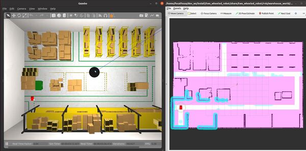
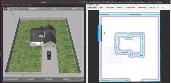
In this tutorial, I will show you how to create a path planner plugin that will enable a robot to move in straight lines using the ROS 2 Navigation Stack (also known as Nav2). Here is the final output you will be able to achieve after going through this tutorial:
Real-World Applications
The application that we will develop in this tutorial can be used in a number of real-world robotic applications:
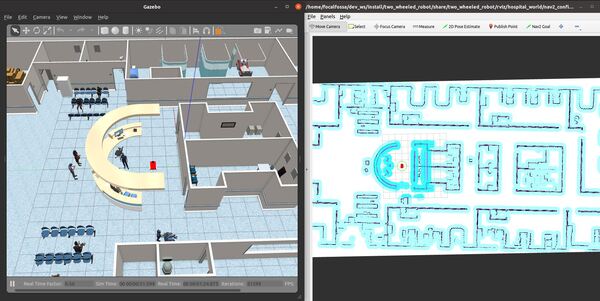
- Hospitals and Medical Centers
- House
- Hotels (e.g. Room Service)
- Offices
- Restaurants
- Warehouses
- And more…
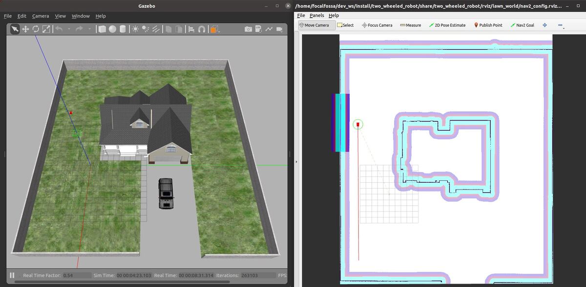
We will focus on creating an autonomous lawn mower in this tutorial.
Prerequisites
You can find the files for this post here on my Google Drive. Credit to this GitHub repository for the code.
Download and Build the Navigation 2 Tutorials Packages
Let’s create a ROS 2 package inside our workspace.
In a new terminal window, move to the src folder of your workspace.
cd ~/dev_ws/src
Download the navigation_2 tutorials package.
git clone https://github.com/ros-planning/navigation2_tutorials.git
Move to the root of your workspace.
cd ~/dev_ws/
Check that dependencies are installed for all packages in the workspace.
rosdep install --from-paths src --ignore-src -r -y
You should see a message that says:
“ERROR: the following packages/stacks could not have their rosdep keys resolved to system dependencies: sam_bot_description…”... go to the package.xml file inside the sam_bot_description folder and change rviz to rviz2.
Now run it again.
cd ~/dev_ws/
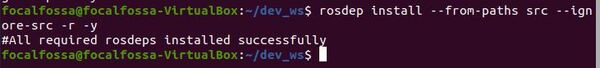
rosdep install --from-paths src --ignore-src -r -y
Here is the message you should see:
#All required rosdeps installed successfully
Now build the package by typing the following command:
colcon build
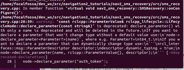
You will see some errors that look like this:
rclcpp_lifecycle::LifecycleNode::declare_parameter(const string&)’ is deprecated: declare_parameter() with only a name is deprecated and will be deleted in the future…
Go to your sms_recovery.cpp file inside this directory:
cd ~/dev_ws/src/navigation2_tutorials/nav2_sms_recovery/src
gedit sms_recovery.cpp
Make sure the code looks like this (note the changes made to the node->declare_parameter lines):
// Copyright (c) 2020 Samsung Research America
// This code is licensed under MIT license (see LICENSE.txt for details)

#include <cmath>
#include <chrono>
#include <memory>
#include <string>

#include "nav2_sms_recovery/sms_recovery.hpp"

namespace nav2_sms_recovery
{

SMSRecovery::SMSRecovery()
: Recovery<Action>()
{
}

SMSRecovery::~SMSRecovery()
{
}

void SMSRecovery::onConfigure()
{
  auto node = node_.lock();
  node->declare_parameter<std::string>("account_sid");
  _account_sid = node->get_parameter("account_sid").as_string();
  node->declare_parameter<std::string>("auth_token");
  _auth_token = node->get_parameter("auth_token").as_string();
  node->declare_parameter<std::string>("from_number");
  _from_number = node->get_parameter("from_number").as_string();
  node->declare_parameter<std::string>("to_number");
  _to_number = node->get_parameter("to_number").as_string();
  _twilio = std::make_shared<twilio::Twilio>(_account_sid, _auth_token);
}

Status SMSRecovery::onRun(const std::shared_ptr<const Action::Goal> command)
{
  auto node = node_.lock();
  std::string response;
  bool message_success = _twilio->send_message(
    _to_number,
    _from_number,
    command->message,
    response,
    "",
    false);

  if (!message_success) {
    RCLCPP_INFO(node->get_logger(), "SMS send failed.");
    return Status::FAILED;
  }

  RCLCPP_INFO(node->get_logger(), "SMS sent successfully!");
  return Status::SUCCEEDED;
}

Status SMSRecovery::onCycleUpdate()
{
  return Status::SUCCEEDED;
}

}  // namespace nav2_sms_recovery

#include "pluginlib/class_list_macros.hpp"
PLUGINLIB_EXPORT_CLASS(nav2_sms_recovery::SMSRecovery, nav2_core::Recovery)
Save the file and close it.
Now build the packages again.
cd ~/dev_ws/
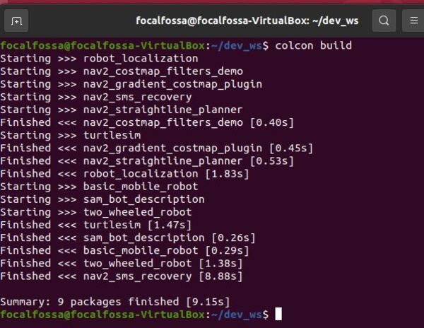
colcon build
Here is the output:
Here is my final navigation_2_tutorials folder that contains the nav2_straightline_planner package.
You can learn more about the nav2_straightline_planner plugin here.
The code that generates the straight-line path from the starting location to the goal location is the straight_line_planner.cpp file inside the src folder of the nav2_straightline_planner package.
Add the Launch File
Add the launch file.
cd ~/dev_ws/src/two_wheeled_robot/launch/lawn_world
gedit lawn_world_straightline.launch.py
# Author: Addison Sears-Collins
# Date: September 28, 2021
# Description: Launch a two-wheeled robot using the ROS 2 Navigation Stack.
#              The spawning of the robot is performed by the Gazebo-ROS spawn_entity node.
#              The robot must be in both SDF and URDF format.
#              If you want to spawn the robot in a pose other than the default, be sure to set that inside
#              the nav2_params_path yaml file: amcl ---> initial_pose: [x, y, z, yaw]
# https://automaticaddison.com

import os
from launch import LaunchDescription
from launch.actions import DeclareLaunchArgument, IncludeLaunchDescription
from launch.conditions import IfCondition, UnlessCondition
from launch.launch_description_sources import PythonLaunchDescriptionSource
from launch.substitutions import Command, LaunchConfiguration, PythonExpression
from launch_ros.actions import Node
from launch_ros.substitutions import FindPackageShare

def generate_launch_description():
  package_name = 'two_wheeled_robot'
  robot_name_in_model = 'two_wheeled_robot'
  default_launch_dir = 'launch'
  gazebo_models_path = 'models'
  map_file_path = 'maps/lawn_world/lawn_world.yaml'
  nav2_params_path = 'params/lawn_world/nav2_params_straightline.yaml'
  robot_localization_file_path = 'config/ekf.yaml'
  rviz_config_file_path = 'rviz/lawn_world/nav2_config.rviz'
  sdf_model_path = 'models/two_wheeled_robot_description/model.sdf'
  urdf_file_path = 'urdf/two_wheeled_robot.urdf'
  world_file_path = 'worlds/lawn.world'

  # Pose where we want to spawn the robot
  spawn_x_val = '0.0'
  spawn_y_val = '0.0'
  spawn_z_val = '0.0'
  spawn_yaw_val = '0.0'

  ########## You do not need to change anything below this line ###############

  # Set the path to different files and folders.
  pkg_gazebo_ros = FindPackageShare(package='gazebo_ros').find('gazebo_ros')
  pkg_share = FindPackageShare(package=package_name).find(package_name)
  default_launch_dir = os.path.join(pkg_share, default_launch_dir)
  default_urdf_model_path = os.path.join(pkg_share, urdf_file_path)
  robot_localization_file_path = os.path.join(pkg_share, robot_localization_file_path)
  default_rviz_config_path = os.path.join(pkg_share, rviz_config_file_path)
  world_path = os.path.join(pkg_share, world_file_path)
  gazebo_models_path = os.path.join(pkg_share, gazebo_models_path)
  os.environ["GAZEBO_MODEL_PATH"] = gazebo_models_path
  nav2_dir = FindPackageShare(package='nav2_bringup').find('nav2_bringup')
  nav2_launch_dir = os.path.join(nav2_dir, 'launch')
  sdf_model_path = os.path.join(pkg_share, sdf_model_path)
  static_map_path = os.path.join(pkg_share, map_file_path)
  nav2_params_path = os.path.join(pkg_share, nav2_params_path)
  nav2_bt_path = FindPackageShare(package='nav2_bt_navigator').find('nav2_bt_navigator')

  # Launch configuration variables specific to simulation
  autostart = LaunchConfiguration('autostart')
  headless = LaunchConfiguration('headless')
  map_yaml_file = LaunchConfiguration('map')
  namespace = LaunchConfiguration('namespace')
  params_file = LaunchConfiguration('params_file')
  rviz_config_file = LaunchConfiguration('rviz_config_file')
  sdf_model = LaunchConfiguration('sdf_model')
  slam = LaunchConfiguration('slam')
  urdf_model = LaunchConfiguration('urdf_model')
  use_namespace = LaunchConfiguration('use_namespace')
  use_robot_state_pub = LaunchConfiguration('use_robot_state_pub')
  use_rviz = LaunchConfiguration('use_rviz')
  use_sim_time = LaunchConfiguration('use_sim_time')
  use_simulator = LaunchConfiguration('use_simulator')
  world = LaunchConfiguration('world')

  # Map fully qualified names to relative ones so the node's namespace can be prepended.
  # In case of the transforms (tf), currently, there doesn't seem to be a better alternative
  # https://github.com/ros/geometry2/issues/32
  # https://github.com/ros/robot_state_publisher/pull/30
  # TODO(orduno) Substitute with `PushNodeRemapping`
  #              https://github.com/ros2/launch_ros/issues/56
  remappings = [('/tf', 'tf'),
                ('/tf_static', 'tf_static')]

  # Declare the launch arguments
  declare_namespace_cmd = DeclareLaunchArgument(
    name='namespace',
    default_value='',
    description='Top-level namespace')

  declare_use_namespace_cmd = DeclareLaunchArgument(
    name='use_namespace',
    default_value='false',
    description='Whether to apply a namespace to the navigation stack')

  declare_autostart_cmd = DeclareLaunchArgument(
    name='autostart',
    default_value='true',
    description='Automatically startup the nav2 stack')

  declare_map_yaml_cmd = DeclareLaunchArgument(
    name='map',
    default_value=static_map_path,
    description='Full path to map file to load')

  declare_params_file_cmd = DeclareLaunchArgument(
    name='params_file',
    default_value=nav2_params_path,
    description='Full path to the ROS2 parameters file to use for all launched nodes')

  declare_rviz_config_file_cmd = DeclareLaunchArgument(
    name='rviz_config_file',
    default_value=default_rviz_config_path,
    description='Full path to the RVIZ config file to use')

  declare_sdf_model_path_cmd = DeclareLaunchArgument(
    name='sdf_model',
    default_value=sdf_model_path,
    description='Absolute path to robot sdf file')

  declare_simulator_cmd = DeclareLaunchArgument(
    name='headless',
    default_value='False',
    description='Whether to execute gzclient')

  declare_slam_cmd = DeclareLaunchArgument(
    name='slam',
    default_value='False',
    description='Whether to run SLAM')

  declare_urdf_model_path_cmd = DeclareLaunchArgument(
    name='urdf_model',
    default_value=default_urdf_model_path,
    description='Absolute path to robot urdf file')

  declare_use_robot_state_pub_cmd = DeclareLaunchArgument(
    name='use_robot_state_pub',
    default_value='True',
    description='Whether to start the robot state publisher')

  declare_use_rviz_cmd = DeclareLaunchArgument(
    name='use_rviz',
    default_value='True',
    description='Whether to start RVIZ')

  declare_use_sim_time_cmd = DeclareLaunchArgument(
    name='use_sim_time',
    default_value='true',
    description='Use simulation (Gazebo) clock if true')

  declare_use_simulator_cmd = DeclareLaunchArgument(
    name='use_simulator',
    default_value='True',
    description='Whether to start the simulator')

  declare_world_cmd = DeclareLaunchArgument(
    name='world',
    default_value=world_path,
    description='Full path to the world model file to load')

  # Specify the actions

  # Start Gazebo server
  start_gazebo_server_cmd = IncludeLaunchDescription(
    PythonLaunchDescriptionSource(os.path.join(pkg_gazebo_ros, 'launch', 'gzserver.launch.py')),
    condition=IfCondition(use_simulator),
    launch_arguments={'world': world}.items())

  # Start Gazebo client
  start_gazebo_client_cmd = IncludeLaunchDescription(
    PythonLaunchDescriptionSource(os.path.join(pkg_gazebo_ros, 'launch', 'gzclient.launch.py')),
    condition=IfCondition(PythonExpression([use_simulator, ' and not ', headless])))

  # Launch the robot
  spawn_entity_cmd = Node(
    package='gazebo_ros',
    executable='spawn_entity.py',
    arguments=['-entity', robot_name_in_model,
               '-file', sdf_model,
                  '-x', spawn_x_val,
                  '-y', spawn_y_val,
                  '-z', spawn_z_val,
                  '-Y', spawn_yaw_val],
       output='screen')

  # Start robot localization using an Extended Kalman filter
  start_robot_localization_cmd = Node(
    package='robot_localization',
    executable='ekf_node',
    name='ekf_filter_node',
    output='screen',
    parameters=[robot_localization_file_path,
    {'use_sim_time': use_sim_time}])

  # Subscribe to the joint states of the robot, and publish the 3D pose of each link.
  start_robot_state_publisher_cmd = Node(
    condition=IfCondition(use_robot_state_pub),
    package='robot_state_publisher',
    executable='robot_state_publisher',
    namespace=namespace,
    parameters=[{'use_sim_time': use_sim_time,
    'robot_description': Command(['xacro ', urdf_model])}],
    remappings=remappings,
    arguments=[default_urdf_model_path])

  # Launch RViz
  start_rviz_cmd = Node(
    condition=IfCondition(use_rviz),
    package='rviz2',
    executable='rviz2',
    name='rviz2',
    output='screen',
    arguments=['-d', rviz_config_file])

  # Launch the ROS 2 Navigation Stack
  start_ros2_navigation_cmd = IncludeLaunchDescription(
    PythonLaunchDescriptionSource(os.path.join(nav2_launch_dir, 'bringup_launch.py')),
    launch_arguments = {'namespace': namespace,
                        'use_namespace': use_namespace,
                        'slam': slam,
                        'map': map_yaml_file,
                        'use_sim_time': use_sim_time,
                        'params_file': params_file,
                        'autostart': autostart}.items())

  # Create the launch description and populate
  ld = LaunchDescription()

  # Declare the launch options
  ld.add_action(declare_namespace_cmd)
  ld.add_action(declare_use_namespace_cmd)
  ld.add_action(declare_autostart_cmd)
  ld.add_action(declare_map_yaml_cmd)
  ld.add_action(declare_params_file_cmd)
  ld.add_action(declare_rviz_config_file_cmd)
  ld.add_action(declare_sdf_model_path_cmd)
  ld.add_action(declare_simulator_cmd)
  ld.add_action(declare_slam_cmd)
  ld.add_action(declare_urdf_model_path_cmd)
  ld.add_action(declare_use_robot_state_pub_cmd)
  ld.add_action(declare_use_rviz_cmd)
  ld.add_action(declare_use_sim_time_cmd)
  ld.add_action(declare_use_simulator_cmd)
  ld.add_action(declare_world_cmd)

  # Add any actions
  ld.add_action(start_gazebo_server_cmd)
  ld.add_action(start_gazebo_client_cmd)
  ld.add_action(spawn_entity_cmd)
  ld.add_action(start_robot_localization_cmd)
  ld.add_action(start_robot_state_publisher_cmd)
  ld.add_action(start_rviz_cmd)
  ld.add_action(start_ros2_navigation_cmd)

  return ld
Save and close.
Add the Parameters File
Add the Nav2 parameters.
cd ~/dev_ws/src/two_wheeled_robot/params/lawn_world
gedit nav2_params_straightline.yaml
Save and close.
Now we build the package.
cd ~/dev_ws/
colcon build
Launch the Autonomous Robotic Lawn Mower
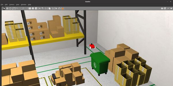
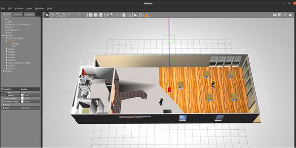
Open a new terminal and launch the robot in a Gazebo world.
ros2 launch two_wheeled_robot lawn_world_straightline.launch.py
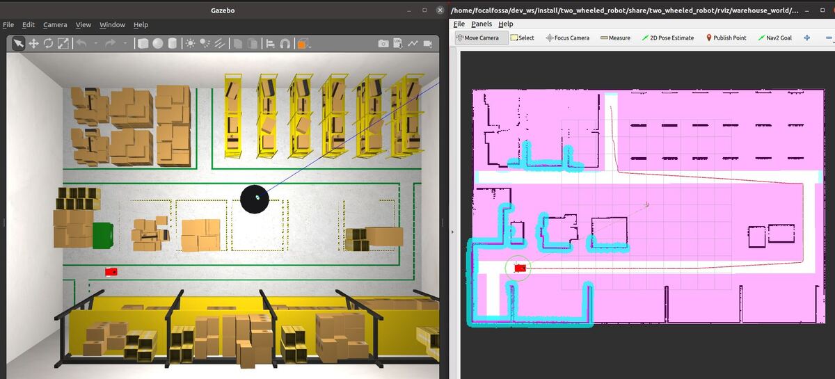
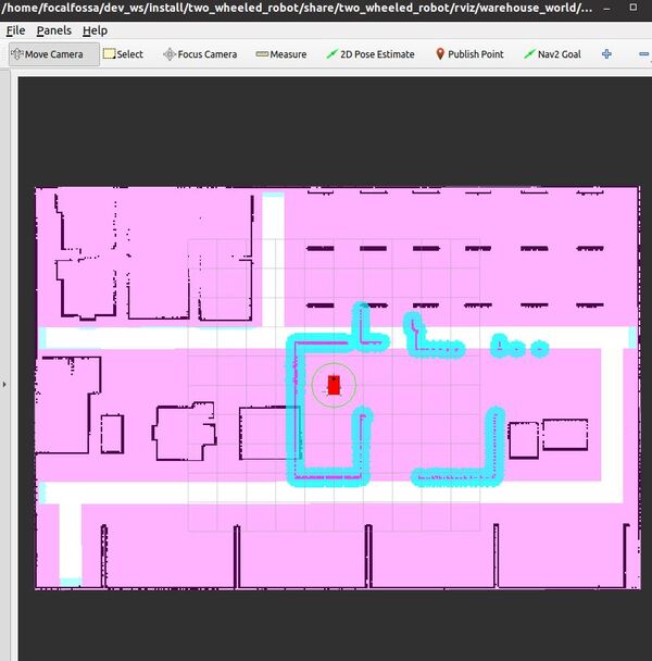
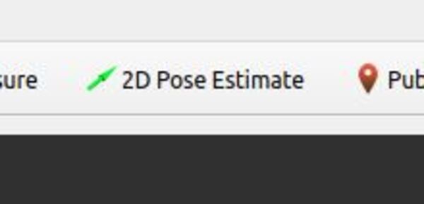
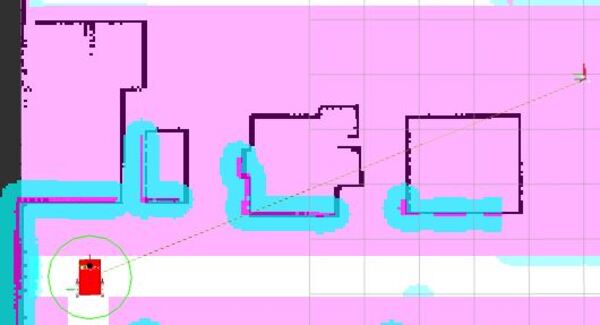
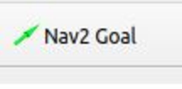
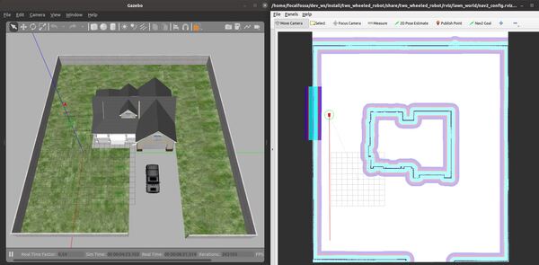
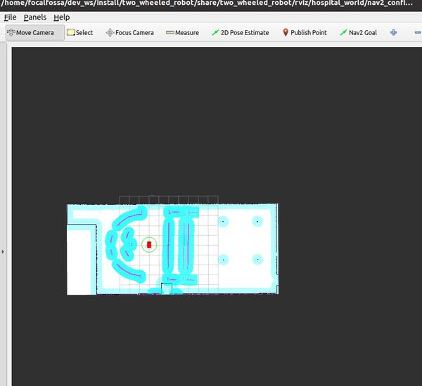
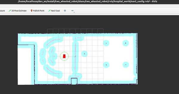
Now send the robot on a straight-line path by clicking the “Nav2 Goal” button at the top of RViz and clicking on a goal location.
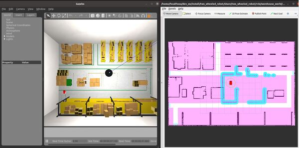
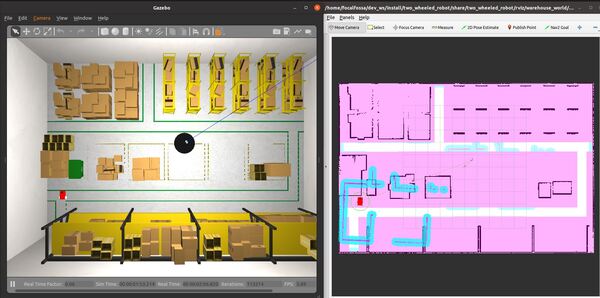
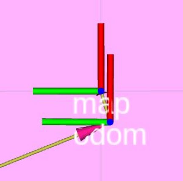
The robot will move along a straight-line path to the goal.
A success message will print once the robot has reached the goal location.
That’s it! Keep building!