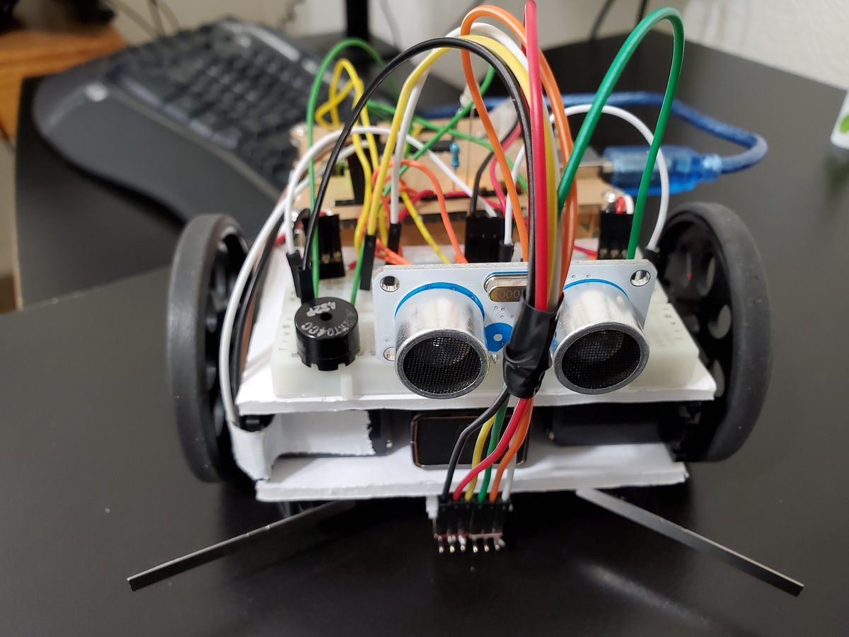
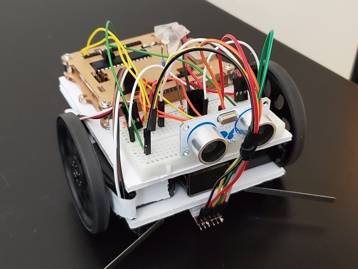
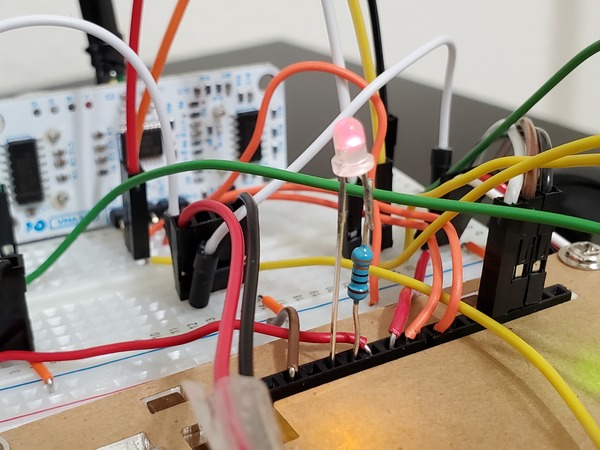
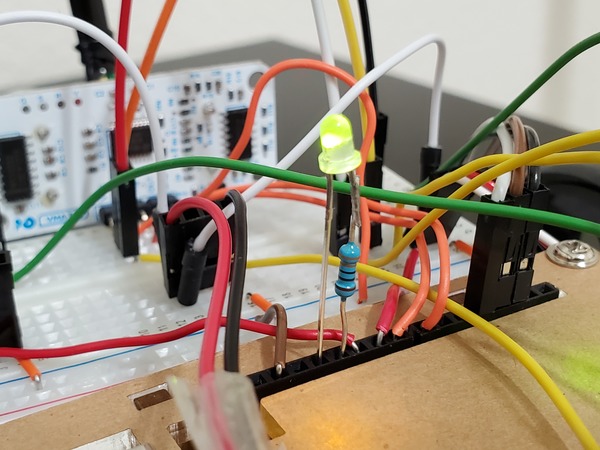
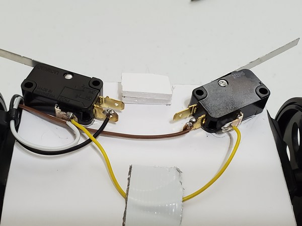
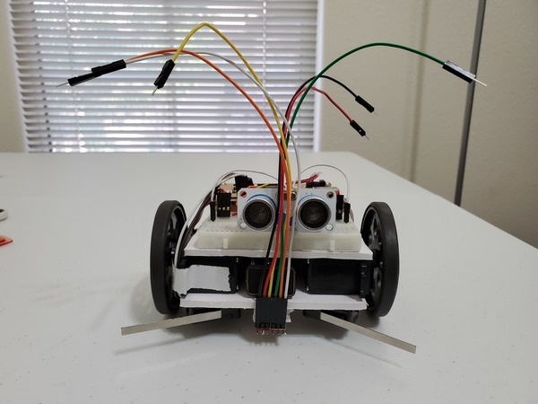
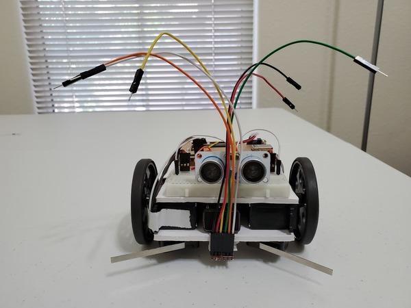
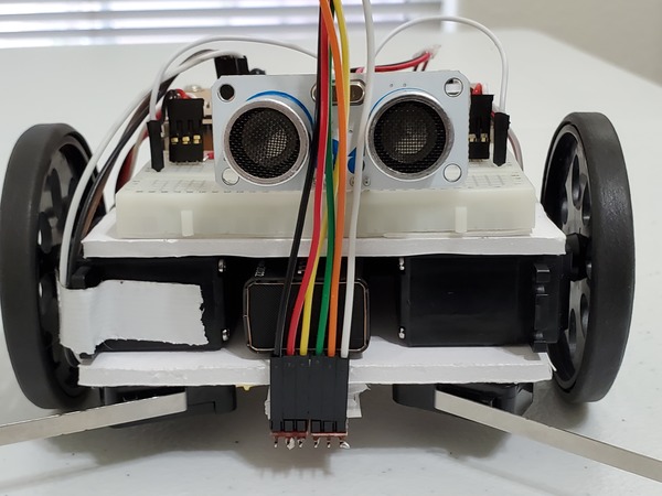
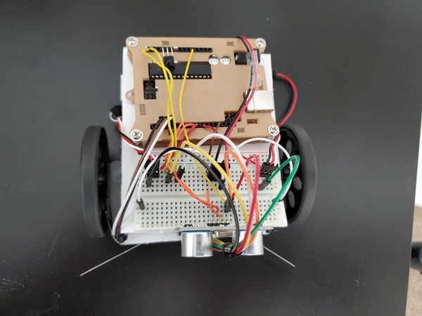
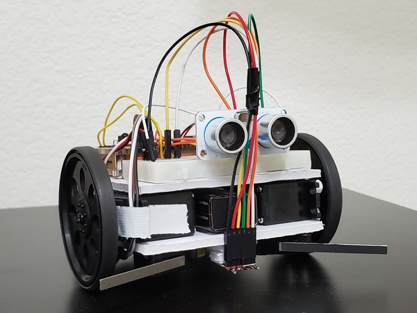
In this post, I’ll show you how to add sound to a wheeled robot.
Shout out to the late Gordon McComb for this project idea. He is the author of an excellent book that I recommend buying if you’re getting started with robotics: How to Make a Robot.
Requirements
Here are the requirements:
- Build a wheeled robot that makes sound before it backs up.
You Will Need
The following components are used in this project. You will need:
Directions
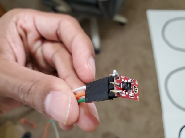
Get the Piezo Transducer.
Stick the positive lead of the transducer into cell j26. Stick the other lead of the transducer into cell j29.
Connect digital pin 5 of the Arduino board to cell f26 of the breadboard.
Connect f29 to e29 with a male to male jumper wire, or just make sure that j29 is electrically connected to Ground.
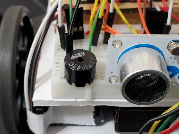
Upload the following sketch to the Arduino breadboard to test the Piezo transducer.
#define SPKR 5

/**
 * Test the piezo transducer
 * connected to pin 5
 *
 * @author Addison Sears-Collins
 * @version 1.0 2019-05-15
 */

void setup() {
}

// Play sounds over and
// over again
void loop() {
   tone(SPKR, 247, 300); //247 Hz, 300ms
   delay(200);
   tone(SPKR, 131, 300);
   delay(200);
   tone(SPKR, 1175, 300);
   delay(200);
   tone(SPKR, 262, 300);
   delay(200);
   tone(SPKR, 1175, 300);
   delay(200);
   tone(SPKR, 131, 300);
   delay(200);
   tone(SPKR, 262, 300);
   delay(200);
   tone(SPKR, 1175, 300);
   delay(200);
   tone(SPKR, 247, 300); //247 Hz, 300ms
   delay(200);
}
Upload the following sketch to the Arduino breadboard in order to cause the robot to make sound just before it backs up.
#include <Servo.h>

/**
 *  This robot will move around a room and when it
 *  bumps into an object, it will turn around and
 *  go in another direction. It will make a noise
 *  just before it backs up.
 *
 * @author Addison Sears-Collins
 * @version 1.0 2019-05-12
 */

#define SPKR 5

// Create two servo objects, one for each wheel
Servo right_servo;
Servo left_servo;

// Volatile keyword is used because these variables
// can change at any time without any action having been
// taken by the compiled code.

volatile int left_switch = LOW;   // Left switch flag
volatile int right_switch = LOW;  // Right switch flag
boolean already_started = false;

/*
 *  This setup code is run only once, when Arudino is
 *  supplied with power.
 */
void setup() {
  // Set the pin modes for the switches
  pinMode(2, INPUT); // Right switch is input
  pinMode(3, INPUT); // Left switch is input
  pinMode(4, OUTPUT); // Pin 4 is ground

  // Turn on the internal pull up resistors for the switches
  // Keeps input from floating when the switches are not
  // pressed
  digitalWrite(2, HIGH);     // Right switch default to high
  digitalWrite(3, HIGH);     // Left switch default to high
  digitalWrite(4, LOW);      // Pin 4 default is ground

  right_servo.attach(9);      // Right servo is pin 9
  left_servo.attach(10);      // Left servo is pin 10

  // Declare the interrupts
  // attachInterrupt(digitalPinToInterrupt(pin), ISR, mode)
  // Interrupt when go from high to low
  attachInterrupt(digitalPinToInterrupt(2), hit_right, FALLING);
  attachInterrupt(digitalPinToInterrupt(3), hit_left, FALLING);

  already_started = true;  // Bot can now move
}

void loop() {
  if (left_switch == HIGH) {       // If the left switch is hit
    go_backwards();                // Go backwards for one second
    delay(1000);
    go_right();                    // Turn to the right for one second
    delay(1000);
    go_forward();                  // Move forward
    left_switch = LOW;             // Reset the flag
  }

  if (right_switch == HIGH) {      // If the right switch is hit
    go_backwards();                // Go backwards for one second
    delay(1000);
    go_left();                     // Turn left for one second
    delay(1000);
    go_forward();                  // Move forward
    right_switch = LOW;            // Reset the flag
  }
}

// Interrupt routine for left switch bumping into an object
void hit_left() {
  if (already_started)              // Valid if the program has begun
    left_switch = HIGH;
}

// Interrupt routine for right switch bumping into an object
void hit_right() {
  if (already_started)              // Valid if the program has begun
    right_switch = HIGH;
}

/*
 *  Forwards, backwards, right, left, stop.
 */
void go_forward() {
  right_servo.write(0);
  left_servo.write(180);
}
void go_backwards() {

  // Make a noise before you go backwards
  tone(SPKR, 247, 300); //247 Hz, 300ms
  delay(200);
  tone(SPKR, 131, 300);
  delay(200);
  tone(SPKR, 1175, 300);
  delay(200);
  right_servo.write(180);
  left_servo.write(0);
}
void go_right() {
  right_servo.write(180);
  left_servo.write(180);
}
void go_left() {
  right_servo.write(0);
  left_servo.write(0);
}
/*
void stop_all() {
  right_servo.write(90); // Tweak the 90
  left_servo.write(90);  // Tweak the 90
}
*/

