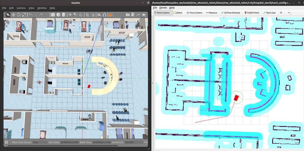
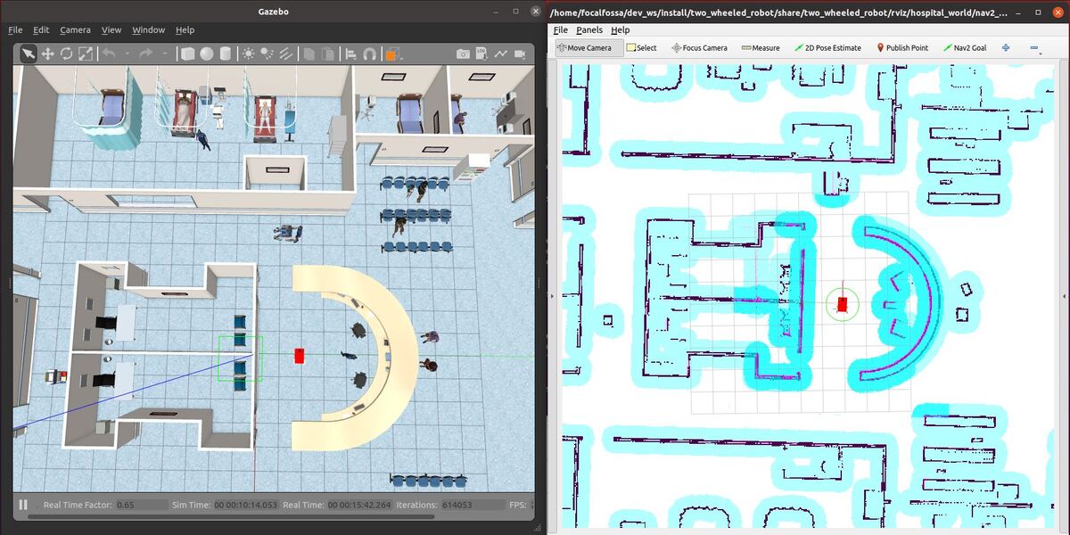
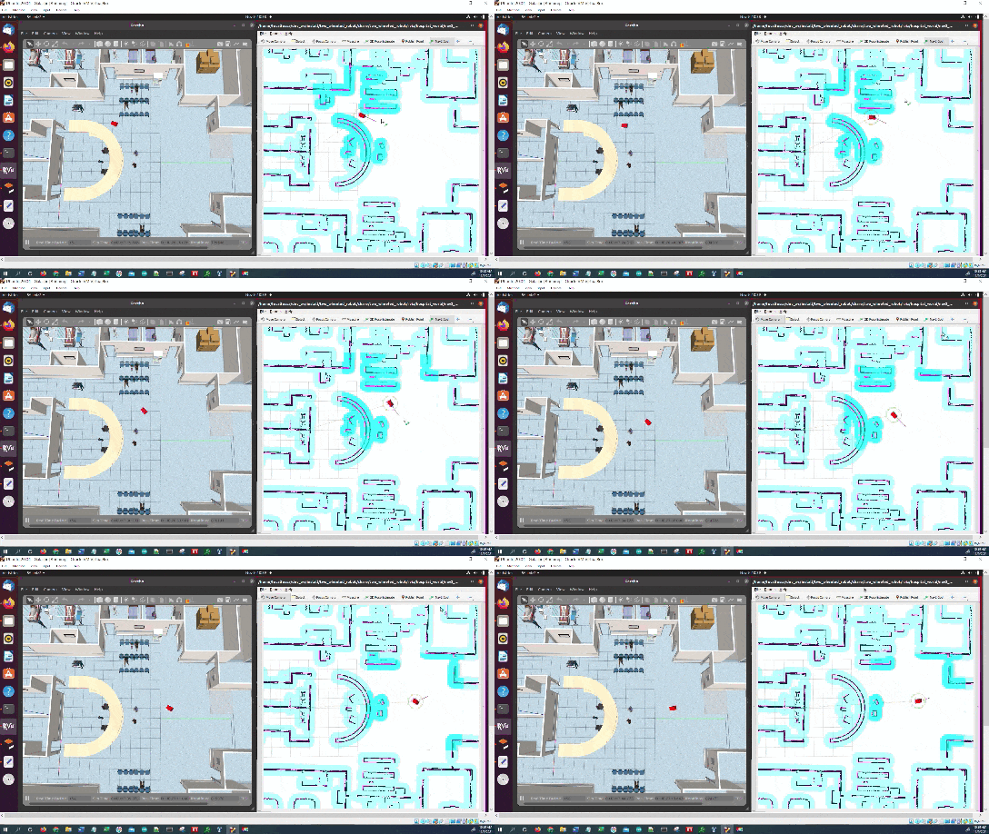
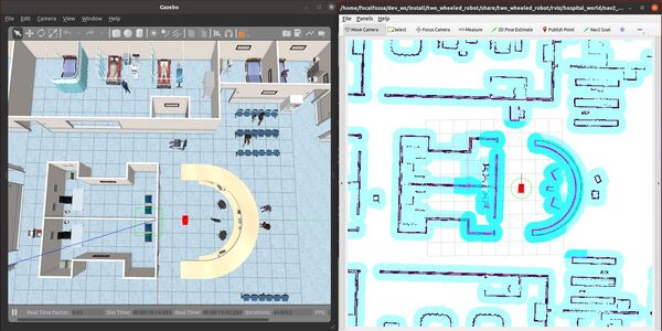
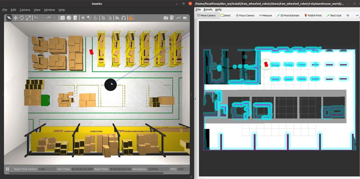
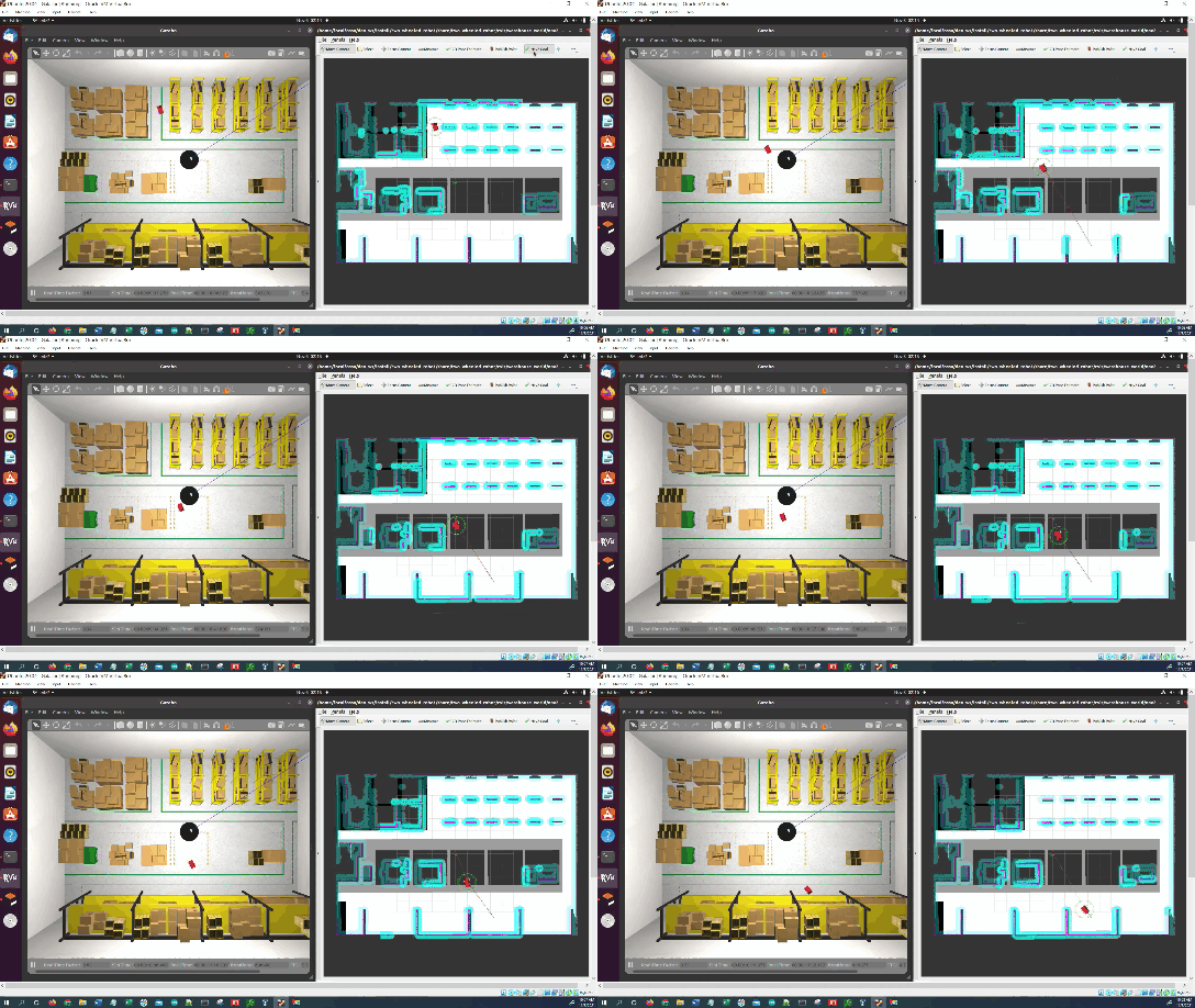
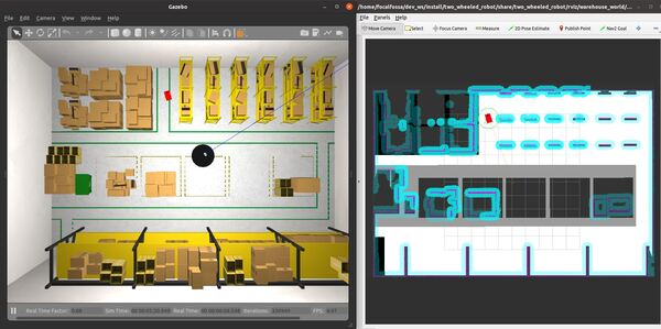
In this tutorial, I will show you how to use the Regulated Pure Pursuit controller plugin that comes with the ROS 2 Navigation Stack (also known as Nav2). This controller plugin is used to track a path that is generated by a path planning algorithm. I have found that Regulated Pure Pursuit generates smoother control than any other control algorithm I have used with Nav2, including the default DWB algorithm. Here is the final output you will be able to achieve after going through this tutorial:
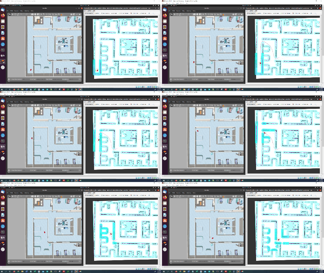
At a high level, with the pure pursuit algorithm, we assume that we know the path to a goal location. The algorithm calculates the linear velocity and angular velocity that will move the robot from its current location to some look-ahead point along the path in front of the robot.
You can read more about the pure pursuit algorithm in the original paper.
The Regulated Pure Pursuit algorithm is an improvement over the pure pursuit algorithm. What I like about this algorithm is that it slows down while making sharp turns around blind corners.
You can read about the Regulated Pure Pursuit algorithm on this page. That page also has the different parameters that you can configure inside your parameters yaml file (which I will give you later in this tutorial).
Prerequisites
- ROS 2 Foxy Fitzroy installed on Ubuntu Linux 20.04 or newer. I am using ROS 2 Galactic, which is the latest version of ROS 2 as of the date of this post.
- You have already created a ROS 2 workspace. The name of our workspace is “dev_ws”, which stands for “development workspace.”
- You have Python 3.7 or higher.
- (Optional) You have completed my Ultimate Guide to the ROS 2 Navigation Stack.
- (Optional) You have a package named two_wheeled_robot inside your ~/dev_ws/src folder, which I set up in this post. If you have another package, that is fine.
- (Optional) You know how to load a world file into Gazebo using ROS 2.
You can find the files for this post here on my Google Drive.
Create a World
Open a terminal window, and move to your package.
cd ~/dev_ws/src/two_wheeled_robot/worlds
Make sure this world is inside this folder. The name of the file is hospital.world.
Create a Map
Open a terminal window, and move to your package.
cd ~/dev_ws/src/two_wheeled_robot/maps/hospital_world
Make sure the pgm and yaml map files are inside this folder.
My hospital map is made up of two files:
- hospital_world.pgm
- hospital_world.yaml
Create the Parameters File
Let’s create the parameters file.
Open a terminal window, and move to your package.
cd ~/dev_ws/src/two_wheeled_robot/params/hospital_world
Add the nav2_params_regulated_pure_pursuit.yaml file from this folder.
Create the RViz Configuration File
Let’s create the RViz configuration file.
Open a terminal window, and move to your package.
cd ~/dev_ws/src/two_wheeled_robot/rviz/hospital_world
Add the nav2_config.rviz file from this folder.
Create the Launch File
Let’s create the launch file.
Open a terminal window, and move to your package.
cd ~/dev_ws/src/two_wheeled_robot/launch/hospital_world
Add the hospital_world_regulated_pure_pursuit.launch.py file from this folder.
Here is the code:
# Author: Addison Sears-Collins
# Date: November 9, 2021
# Description: Launch a two-wheeled robot using the ROS 2 Navigation Stack.
#              The spawning of the robot is performed by the Gazebo-ROS spawn_entity node.
#              The robot must be in both SDF and URDF format.
#              If you want to spawn the robot in a pose other than the default, be sure to set that inside
#              the nav2_params_path yaml file: amcl ---> initial_pose: [x, y, z, yaw]
#              The robot uses the Regulated Pure Pursuit Controller for path tracking.
# https://automaticaddison.com

import os
from launch import LaunchDescription
from launch.actions import DeclareLaunchArgument, IncludeLaunchDescription
from launch.conditions import IfCondition, UnlessCondition
from launch.launch_description_sources import PythonLaunchDescriptionSource
from launch.substitutions import Command, LaunchConfiguration, PythonExpression
from launch_ros.actions import Node
from launch_ros.substitutions import FindPackageShare

def generate_launch_description():
  package_name = 'two_wheeled_robot'
  robot_name_in_model = 'two_wheeled_robot'
  default_launch_dir = 'launch'
  gazebo_models_path = 'models'
  map_file_path = 'maps/hospital_world/hospital_world.yaml'
  nav2_params_path = 'params/hospital_world/nav2_params_regulated_pure_pursuit.yaml'
  robot_localization_file_path = 'config/ekf.yaml'
  rviz_config_file_path = 'rviz/hospital_world/nav2_config.rviz'
  sdf_model_path = 'models/two_wheeled_robot_description/model.sdf'
  urdf_file_path = 'urdf/two_wheeled_robot.urdf'
  world_file_path = 'worlds/hospital.world'

  # Pose where we want to spawn the robot
  spawn_x_val = '0.0'
  spawn_y_val = '2.0'
  spawn_z_val = '0.25'
  spawn_yaw_val = '0.0'

  ########## You do not need to change anything below this line ###############

  # Set the path to different files and folders.
  pkg_gazebo_ros = FindPackageShare(package='gazebo_ros').find('gazebo_ros')
  pkg_share = FindPackageShare(package=package_name).find(package_name)
  default_launch_dir = os.path.join(pkg_share, default_launch_dir)
  default_urdf_model_path = os.path.join(pkg_share, urdf_file_path)
  robot_localization_file_path = os.path.join(pkg_share, robot_localization_file_path)
  default_rviz_config_path = os.path.join(pkg_share, rviz_config_file_path)
  world_path = os.path.join(pkg_share, world_file_path)
  gazebo_models_path = os.path.join(pkg_share, gazebo_models_path)
  os.environ["GAZEBO_MODEL_PATH"] = gazebo_models_path
  nav2_dir = FindPackageShare(package='nav2_bringup').find('nav2_bringup')
  nav2_launch_dir = os.path.join(nav2_dir, 'launch')
  sdf_model_path = os.path.join(pkg_share, sdf_model_path)
  static_map_path = os.path.join(pkg_share, map_file_path)
  nav2_params_path = os.path.join(pkg_share, nav2_params_path)
  nav2_bt_path = FindPackageShare(package='nav2_bt_navigator').find('nav2_bt_navigator')

  # Launch configuration variables specific to simulation
  autostart = LaunchConfiguration('autostart')
  headless = LaunchConfiguration('headless')
  map_yaml_file = LaunchConfiguration('map')
  namespace = LaunchConfiguration('namespace')
  params_file = LaunchConfiguration('params_file')
  rviz_config_file = LaunchConfiguration('rviz_config_file')
  sdf_model = LaunchConfiguration('sdf_model')
  slam = LaunchConfiguration('slam')
  urdf_model = LaunchConfiguration('urdf_model')
  use_namespace = LaunchConfiguration('use_namespace')
  use_robot_state_pub = LaunchConfiguration('use_robot_state_pub')
  use_rviz = LaunchConfiguration('use_rviz')
  use_sim_time = LaunchConfiguration('use_sim_time')
  use_simulator = LaunchConfiguration('use_simulator')
  world = LaunchConfiguration('world')

  # Map fully qualified names to relative ones so the node's namespace can be prepended.
  # In case of the transforms (tf), currently, there doesn't seem to be a better alternative
  # https://github.com/ros/geometry2/issues/32
  # https://github.com/ros/robot_state_publisher/pull/30
  # TODO(orduno) Substitute with `PushNodeRemapping`
  #              https://github.com/ros2/launch_ros/issues/56
  remappings = [('/tf', 'tf'),
                ('/tf_static', 'tf_static')]

  # Declare the launch arguments
  declare_namespace_cmd = DeclareLaunchArgument(
    name='namespace',
    default_value='',
    description='Top-level namespace')

  declare_use_namespace_cmd = DeclareLaunchArgument(
    name='use_namespace',
    default_value='false',
    description='Whether to apply a namespace to the navigation stack')

  declare_autostart_cmd = DeclareLaunchArgument(
    name='autostart',
    default_value='true',
    description='Automatically startup the nav2 stack')

  declare_map_yaml_cmd = DeclareLaunchArgument(
    name='map',
    default_value=static_map_path,
    description='Full path to map file to load')

  declare_params_file_cmd = DeclareLaunchArgument(
    name='params_file',
    default_value=nav2_params_path,
    description='Full path to the ROS2 parameters file to use for all launched nodes')

  declare_rviz_config_file_cmd = DeclareLaunchArgument(
    name='rviz_config_file',
    default_value=default_rviz_config_path,
    description='Full path to the RVIZ config file to use')

  declare_sdf_model_path_cmd = DeclareLaunchArgument(
    name='sdf_model',
    default_value=sdf_model_path,
    description='Absolute path to robot sdf file')

  declare_simulator_cmd = DeclareLaunchArgument(
    name='headless',
    default_value='False',
    description='Whether to execute gzclient')

  declare_slam_cmd = DeclareLaunchArgument(
    name='slam',
    default_value='False',
    description='Whether to run SLAM')

  declare_urdf_model_path_cmd = DeclareLaunchArgument(
    name='urdf_model',
    default_value=default_urdf_model_path,
    description='Absolute path to robot urdf file')

  declare_use_robot_state_pub_cmd = DeclareLaunchArgument(
    name='use_robot_state_pub',
    default_value='True',
    description='Whether to start the robot state publisher')

  declare_use_rviz_cmd = DeclareLaunchArgument(
    name='use_rviz',
    default_value='True',
    description='Whether to start RVIZ')

  declare_use_sim_time_cmd = DeclareLaunchArgument(
    name='use_sim_time',
    default_value='true',
    description='Use simulation (Gazebo) clock if true')

  declare_use_simulator_cmd = DeclareLaunchArgument(
    name='use_simulator',
    default_value='True',
    description='Whether to start the simulator')

  declare_world_cmd = DeclareLaunchArgument(
    name='world',
    default_value=world_path,
    description='Full path to the world model file to load')

  # Specify the actions

  # Start Gazebo server
  start_gazebo_server_cmd = IncludeLaunchDescription(
    PythonLaunchDescriptionSource(os.path.join(pkg_gazebo_ros, 'launch', 'gzserver.launch.py')),
    condition=IfCondition(use_simulator),
    launch_arguments={'world': world}.items())

  # Start Gazebo client
  start_gazebo_client_cmd = IncludeLaunchDescription(
    PythonLaunchDescriptionSource(os.path.join(pkg_gazebo_ros, 'launch', 'gzclient.launch.py')),
    condition=IfCondition(PythonExpression([use_simulator, ' and not ', headless])))

  # Launch the robot
  spawn_entity_cmd = Node(
    package='gazebo_ros',
    executable='spawn_entity.py',
    arguments=['-entity', robot_name_in_model,
               '-file', sdf_model,
                  '-x', spawn_x_val,
                  '-y', spawn_y_val,
                  '-z', spawn_z_val,
                  '-Y', spawn_yaw_val],
       output='screen')

  # Start robot localization using an Extended Kalman filter
  start_robot_localization_cmd = Node(
    package='robot_localization',
    executable='ekf_node',
    name='ekf_filter_node',
    output='screen',
    parameters=[robot_localization_file_path,
    {'use_sim_time': use_sim_time}])

  # Subscribe to the joint states of the robot, and publish the 3D pose of each link.
  start_robot_state_publisher_cmd = Node(
    condition=IfCondition(use_robot_state_pub),
    package='robot_state_publisher',
    executable='robot_state_publisher',
    namespace=namespace,
    parameters=[{'use_sim_time': use_sim_time,
    'robot_description': Command(['xacro ', urdf_model])}],
    remappings=remappings,
    arguments=[default_urdf_model_path])

  # Launch RViz
  start_rviz_cmd = Node(
    condition=IfCondition(use_rviz),
    package='rviz2',
    executable='rviz2',
    name='rviz2',
    output='screen',
    arguments=['-d', rviz_config_file])

  # Launch the ROS 2 Navigation Stack
  start_ros2_navigation_cmd = IncludeLaunchDescription(
    PythonLaunchDescriptionSource(os.path.join(nav2_launch_dir, 'bringup_launch.py')),
    launch_arguments = {'namespace': namespace,
                        'use_namespace': use_namespace,
                        'slam': slam,
                        'map': map_yaml_file,
                        'use_sim_time': use_sim_time,
                        'params_file': params_file,
                        'autostart': autostart}.items())

  # Create the launch description and populate
  ld = LaunchDescription()

  # Declare the launch options
  ld.add_action(declare_namespace_cmd)
  ld.add_action(declare_use_namespace_cmd)
  ld.add_action(declare_autostart_cmd)
  ld.add_action(declare_map_yaml_cmd)
  ld.add_action(declare_params_file_cmd)
  ld.add_action(declare_rviz_config_file_cmd)
  ld.add_action(declare_sdf_model_path_cmd)
  ld.add_action(declare_simulator_cmd)
  ld.add_action(declare_slam_cmd)
  ld.add_action(declare_urdf_model_path_cmd)
  ld.add_action(declare_use_robot_state_pub_cmd)
  ld.add_action(declare_use_rviz_cmd)
  ld.add_action(declare_use_sim_time_cmd)
  ld.add_action(declare_use_simulator_cmd)
  ld.add_action(declare_world_cmd)

  # Add any actions
  ld.add_action(start_gazebo_server_cmd)
  ld.add_action(start_gazebo_client_cmd)
  #ld.add_action(spawn_entity_cmd)
  ld.add_action(start_robot_localization_cmd)
  ld.add_action(start_robot_state_publisher_cmd)
  ld.add_action(start_rviz_cmd)
  ld.add_action(start_ros2_navigation_cmd)

  return ld
Launch the Launch File
We will now build our package.
cd ~/dev_ws/
colcon build
Open a new terminal and launch the robot in a Gazebo world. All of this is a single command:
ros2 launch two_wheeled_robot hospital_world_regulated_pure_pursuit.launch.py
Select the Nav2 Goal button at the top of RViz, and click somewhere on the map to command the robot to navigate to any reachable goal location.
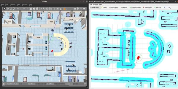
The robot will move to the goal location.
That’s it! Keep building!

