In this tutorial, we are going to build basic programs using Python.
Prerequisites
- You have completed this tutorial.
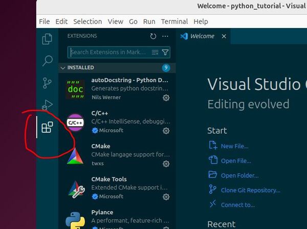
- I am using VS Code for my Python development environment, but you are free to use any development environment you wish.
Build a Basic Calculator
Let’s start by building a basic calculator. This exercise will help you understand how to handle user input and perform basic arithmetic operations in Python.
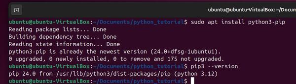
Open a new terminal window, and move to the directory where we will store our code.
cd ~/Documents/python_tutorialI will open VS Code.
code .Right-click in the Explorer pane and select “New File”.
Name the file basic_calculator.py, and press Enter.
First, let’s ask the user to input two numbers. Type the following lines:
num1 = float(input("Enter first number: "))
num2 = float(input("Enter second number: "))
These commands prompt the user for input, converting the input into floating point numbers for arithmetic operations.
Next, we need to ask the user to choose the operation. Add this line:
operation = input("Choose the operation (+, -, *, /): ")
Now, we’ll use conditional statements to perform the operation selected by the user.
if operation == '+':
    result = num1 + num2
elif operation == '-':
    result = num1 - num2
elif operation == '*':
    result = num1 * num2
elif operation == '/':
    if num2 != 0:
        result = num1 / num2
    else:
        result = "Error! Division by zero."
else:
    result = "Invalid operation selected."

print(result)
This if-else structure helps our calculator decide what to do based on the user’s choice.
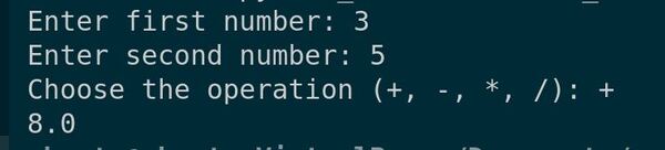
After writing the code, save your file. Let’s now run our program to see how it works.
Enter the numbers and the operation when prompted.
Watch as your program calculates and displays the result.
Making Your Program Executable
Let’s see how to make basic_calculator.py executable. We will do this directly from the command line. This will enhance your workflow by allowing you to run your Python scripts without explicitly calling the Python interpreter each time.
Let’s begin by opening the basic_calculator.py script we created in the previous lecture. Once open, we need to add a shebang line at the very top of the file.
Type the following line as the first line in your file:
#!/usr/bin/env python3
This shebang line tells the system that this script should be run using Python 3, which we’ve installed on our machine. Make sure this line is at the top, before any other code.
After adding the shebang, save your file.
The next step is to make the script executable. We’ll do this using the terminal.
Open your terminal in Visual Studio Code by going to View -> Terminal.
Navigate to the directory where your basic_calculator.py file is located. Now, type the following command:
cd ~/Documents/python_tutorialchmod +x basic_calculator.py This command changes the file’s permissions, making it executable.
Now, you can run your Python script directly from the command line.
To run your script, simply type the following in your terminal:”
./basic_calculator.py 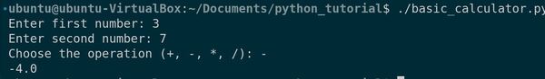
Notice how we didn’t have to type ‘python3’ before our script name. The system recognizes it as an executable file and runs it using the Python interpreter specified in the shebang line.
Go ahead and test different inputs to see how your calculator works now as an executable script.
Doing Basic Calculations
Let’s explore how to perform basic calculations in Python. We’ll cover addition, subtraction, multiplication, division, and a bit about modulus operations.
Let’s get started by opening your code editor. We’ll create a new file named basic_calculations.py.
In this file, we’ll write small code snippets to demonstrate each type of calculation. First, let’s start with addition.
# Addition
print("Addition of 5 + 3 is:", 5 + 3)
This will output the sum of 5 and 3. Now, let’s do subtraction.
# Subtraction
print("Subtraction of 5 - 3 is:", 5 - 3)
Next, we have multiplication.
# Multiplication
print("Multiplication of 5 * 3 is:", 5 * 3)
And then division.
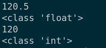
# Division
print("Division of 5 / 3 is:", 5 / 3)
Division in Python gives you a float. If you need the integer quotient, you can use the floor division operator.
# Floor Division
print("Floor division of 5 // 3 is:", 5 // 3)
Lastly, let’s look at the modulus operation, which gives the remainder of a division.
# Modulus
print("Modulus of 5 % 3 is:", 5 % 3)
After typing these examples, save your file. Now, let’s run this script to see the output of these basic calculations.
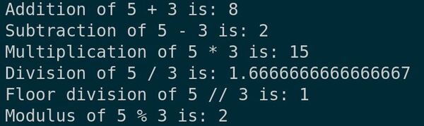
You should see the results for each operation displayed in the terminal. These operations are fundamental to programming and form the basis for more complex algorithms.
Working with Random Values
Let’s learn how to work with random values in Python. This capability is essential for simulating uncertainty in robotics applications and for creating varied testing scenarios.
Let’s start by opening your code editor. We’ll create a new file and name it working_with_random.py.
To generate random numbers, Python provides a module named random. First, we need to import this module.
import random
Let’s begin with generating a random integer. We’ll use the randint function, which returns an integer between the specified range.
# Generate a random integer between 1 and 10
random_integer = random.randint(1, 10)
print("Random integer between 1 and 10:", random_integer)
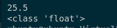
Next, we’ll generate a random float. The random function returns a floating-point number between 0.0 and 1.0.
# Generate a random float
random_float = random.random()
print("Random float between 0.0 and 1.0:", random_float)
Sometimes, you may want to generate a float within a different range. You can do this by multiplying the result of random().
# Generate a random float between 0.0 and 5.0
random_float_in_range = random.random() * 5
print("Random float between 0.0 and 5.0:", random_float_in_range)
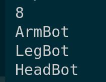
We can also pick a random element from a list. Let’s create a list of colors and select one randomly.
# Pick a random element from a list
colors = ['red', 'blue', 'green', 'yellow']
random_color = random.choice(colors)
print("Random color selected:", random_color)
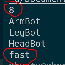
Lastly, if you want to shuffle the items in a list randomly, you can use the shuffle method.
# Shuffle a list
random.shuffle(colors)
print("Shuffled colors:", colors)
After entering these examples, don’t forget to save your file. Now, let’s run the script to see how random values are generated.
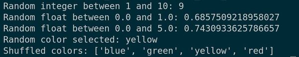
You’ll see the outputs for each of the random operations we scripted. This functionality is invaluable for creating diverse and dynamic environments in simulations and tests.
Using Nan and Infinity
Let’s explore how to work with NaN (Not a Number) and Infinity in Python. These are special floating-point values that you may encounter in numerical computations, especially when dealing with undefined or unbounded values.
Let’s start by opening your code editor. We’ll create a new file and name it nan_and_infinity.py.
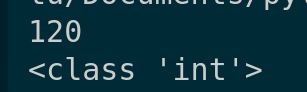
To use NaN and Infinity, Python doesn’t require any special imports as they are part of the standard float type. Let’s start with Infinity.
# Positive Infinity
positive_infinity = float('inf')
print("Positive Infinity:", positive_infinity)

# Negative Infinity
negative_infinity = float('-inf')
print("Negative Infinity:", negative_infinity)
These lines create variables for positive and negative infinity. Operations with these values yield predictable results, following rules of mathematical infinity.
Next, we have NaN. It’s a special value used to denote that a result of a computation cannot be defined in meaningful terms.
# NaN example
not_a_number = float('nan')
print("Example of NaN:", not_a_number)
Let’s see some operations with NaN. Any operation involving NaN typically results in NaN, indicating an invalid result.
# Operations with NaN
print("NaN added to a number:", not_a_number + 5)
print("NaN multiplied by a number:", not_a_number * 2)
Interestingly, comparing NaN with anything, even itself, is always false. This is useful for checking if a value is NaN.
# Checking if a value is NaN
print("Is NaN equal to NaN?:", not_a_number == not_a_number)
To properly check for NaN, we use the math.isnan() function from the math module.
import math
print("Using math.isnan() to check NaN:", math.isnan(not_a_number))
Now, let’s run the script to see how NaN and Infinity behave in Python.
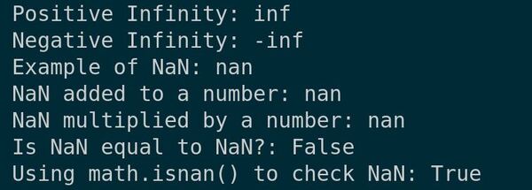
You’ll see the outputs for each operation, illustrating how special floating-point values like NaN and Infinity are handled in Python.
That’s it. You have gotten some good experience building programs in Python to perform fundamental calculations.
Thank you, and I’ll see you in the next tutorial.
Keep building!