In this tutorial, we will cover the top 50 most popular Linux commands that every roboticist should know.
When you work on robotic projects, you will use the Linux terminal all the time. Learning these essential commands will help you work more efficiently.
Please follow along and try the commands in your own Linux environment. Feel free to pause the video when you need to, and have fun experimenting.
Don’t worry about memorizing these commands. Eventually, you will know these commands by heart after you use them again and again throughout your robotics career.
Prerequisites
- You have a computer that is running Ubuntu (I’m running my Ubuntu Linux inside a virtual machine on Windows).
- You have installed ROS 2.
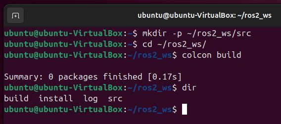
- You have created a ROS 2 workspace.
Ok, let’s open a terminal window, so we can get started!
If you prefer learning through video rather than text, check out the YouTube video below where I walk you through all the commands, step by step. Otherwise, keep reading.
Identifying current user with “whoami”
The first command we’ll cover is “whoami”. This simple command tells you the username of the currently logged-in user.
whoami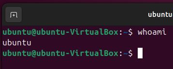
Changing directory with “cd”
The next command we’ll cover is “cd”, which stands for “change directory”. This command allows you to navigate through the filesystem by changing your current working directory.
To use “cd”, type “cd” followed by the path of the directory you want to navigate to, then press Enter.
For example, to navigate to the “Downloads” directory in your home folder, you would type:
cd Downloads/If you want to go back to the folder above where you are now, you can use two dots like this:
cd ..This takes you up one level in your folders.
If you want to go to your ROS 2 workspace, you type:
cd ~/ros2_ws/The tilde symbol ( ~) is a shortcut that means “my home folder.”
Now let’s move to the Documents folder.
cd ~/Documents/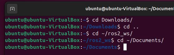
Creating directories with “mkdir”
The “mkdir” command is used to create new directories in the filesystem. It stands for “make directory”.
To create a new directory, type “mkdir” followed by the name you want to give the new directory, then press Enter.
Let’s try it.
mkdir linux_tutorialYou can also create multiple directories at once by specifying multiple names separated by spaces, like this:
mkdir folder1 folder2 folder3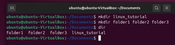
Removing directories with “rm -rf”
The “rm -rf” command is used to delete directories.
To remove a directory, type “rm -rf” followed by the name of the directory you want to remove.
For example,
rm -rf folder3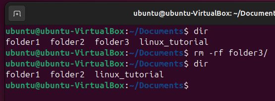
Creating empty files with “touch”
The “touch” command is used to create empty files in the filesystem. It can also be used to update the timestamp of existing files without modifying their contents.
To create a new empty file, type “touch” followed by the name you want to give the file, including the desired extension, then press Enter.
For example, to create an empty text file named “new_file.txt”, you would type:
cd linux_tutorialtouch new_file.txtYou can create multiple empty files at once by specifying multiple names separated by spaces, like this:
touch file1.txt file2.txt file3.txtEditing text files using “nano” and “gedit”
When working with text files in Linux, you can use command-line text editors like “nano” or graphical text editors like “gedit”.
To open a file with “nano”, type “nano” followed by the filename, then press Enter.
For example, to open a file named “example.txt”, you would type:
nano example1.txtIf the file doesn’t exist, “nano” will create a new empty file with that name. You can then type your text, and use keyboard shortcuts like Ctrl+O to save and Ctrl+X to exit.
To open a file with “gedit”, type “gedit” followed by the filename, then press Enter.
Install gedit:
sudo apt-get install geditCreate the file:
gedit example2.txt“gedit” provides a graphical user interface with menu options for saving and closing files.
Listing directory contents with “ls” and “dir”
The “ls” command is used to list the contents of a directory. It stands for “list”.
To list the files and directories in your current location, simply type “ls” and press Enter. This will display a plain listing of the names.
lsThe “dir” command is similar to “ls” but provides a slightly different output format.
dir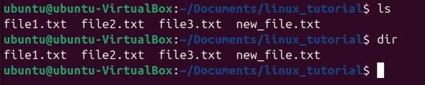
Creating a bash script
Bash scripts are files containing a series of commands that can be executed together.
To create a bash script, start by opening a new file in a text editor (like nano or gedit). Begin the script with the shebang line “#!/bin/bash” to indicate that it should be run with the bash shell.
Then, write your commands one per line. For example:
gedit basic_bash_script_example.shWrite this code:
#!/bin/bash
echo "Hello, world!"
ls -l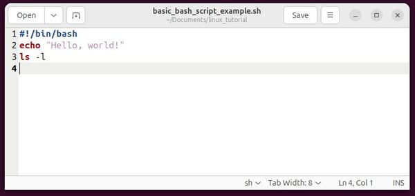
Save the file, and close gedit.
So that we can run the script, we need to make it executable using the “chmod” command with the “+x” option:
chmod +x basic_bash_script_example.shYou can then run your script:
bash basic_bash_script_example.shYou can also type:
./basic_bash_script_example.sh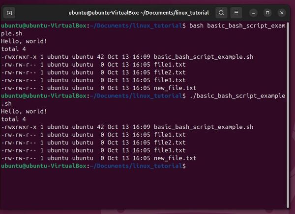
Changing file permissions with “chmod”
The “chmod” command is used to change the permissions of files and directories. It stands for “change mode”.
Permissions specify who can read, write, and execute a file. They are represented by a combination of letters (r for read, w for write, x for execute) for each of the three user classes (owner, group, others).
To see the permissions, create a file now:
touch chmod_example.txtNow type:
ls -laTo change permissions, use “chmod” followed by the desired permission settings and the filename. For example, to give everyone read, write, and execute permissions (r, w, and x, respectively), you type:
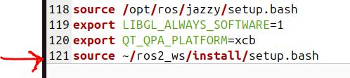
chmod 777 chmod_example.txtExploring the .bashrc file
The .bashrc file is a script that is executed whenever you open a new terminal window. It is located in your home directory and is used to set up your environment, define aliases, and set environment variables.
To edit your .bashrc file, you can use any text editor. For example:
gedit ~/.bashrcCreating command aliases with “alias”
An alias is a shortcut that you can use to run a command or a series of commands. You can define aliases in your .bashrc file so that they are available every time you open a new terminal window.
To create an alias, you use the alias command followed by the name of the alias and the command(s) you want it to run.
Let’s say you want to create a quick command to build a ros2 workspace.
gedit ~/.bashrcWrite this at the bottom of the .bashrc file:
alias build='cd ~/ros2_ws/ && colcon build && source ~/.bashrc'Save the file, and close it.
Now, whenever you want to build your ROS 2 workspace, you can type:
build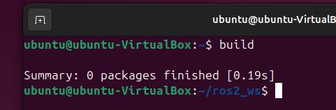
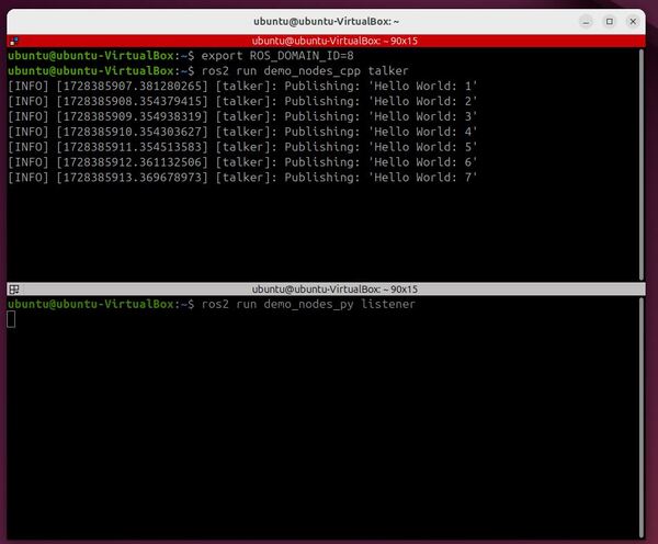
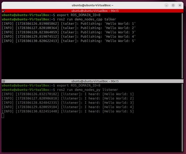
Setting environment variables using export
Environment variables are variables that are available to all the processes running in a terminal window.
You can set environment variables in your .bashrc file so they are available every time you start a new terminal window.
To set an environment variable, use the export command followed by the name of the variable and its value.
For example, to set an environment variable called MY_VAR to the value 8, you can add the following line to your .bashrc file:
gedit ~/.bashrcAdd this at the bottom of the file.
export MY_VAR=8Save the file, and close it.
Open a new terminal window, and verify the value of MY_VAR.
echo $MY_VAR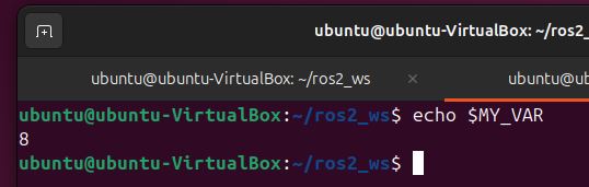
Clearing terminal screen with “clear”
The “clear” command is used to clear the terminal screen, moving the prompt to the top of the screen.
Simply type “clear” and press Enter to clear the screen:
clearThis command is useful when your terminal gets cluttered with output and you want to start with a clean screen.
Exploring options with “intro to options”
Most Linux commands have options that modify their behavior. Options are specified using a dash (“-“) or double dash (“–“) followed by a letter or word.
For example, to see the help information for the “ls” command, you can use:
ls --helpAlternatively, the see the command’s manual, you can type:
man lsThen press “q” to quit.
Determining present working directory with “pwd”
The “pwd” command is used to print the current working directory (the directory you are currently in).
To use this command, simply type “pwd” and press Enter:
pwd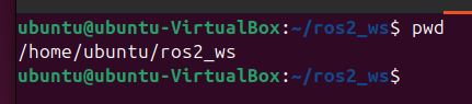
Removing files with “rm”
The “rm” command is used to remove files.
To remove a file, type “rm” followed by the name of the file you want to remove. For example, to remove a file called “chmod_example.txt”:
cd ~/Documents/linux_tutorial/rm chmod_example.txtTo remove a folder, add -rf (recursive + force) to the command:
clear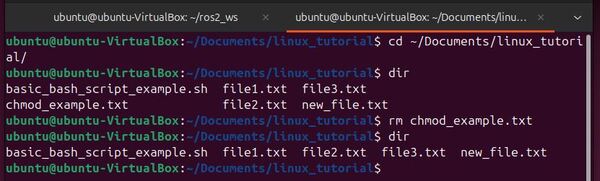
dirmkdir remove_testdirrm -rf remove_testdirOpening files or directories with “open”
The “open” command is used to open files or directories with the default application associated with that file type.
To open a file or directory, type “open” followed by the name or path of the file or directory you want to open. For example:
open ~/ros2_ws/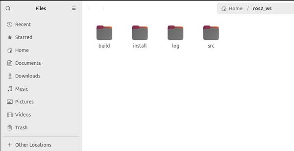
Moving files or directories with “mv”
The “mv” command is used to move files and directories from one location to another. It can also be used to rename files and directories.
To move a file, type “mv” followed by the name of the file you want to move and the destination directory.
For example, to move a file called “new_file.txt” to the “Downloads” directory:
cd ~/Documents/linux_tutorialdirmv new_file.txt ~/Downloads/dirOpen a new terminal to check:
cd ~/Downloads/dirTo rename a file, type “mv” followed by the current filename and the new filename. For example, to rename “old_name.txt” to “new_name.txt”:
cd ~/Documents/linux_tutorialtouch old_name.txtdirmv old_name.txt new_name.txtdir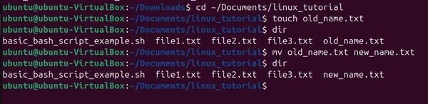
Copying files or directories with “cp”
The “cp” command is used to copy files and directories from one location to another.
To copy a file, type “cp” followed by the name of the file you want to copy and the destination directory.
For example, to copy a file called “copy_example.txt” to the “Downloads” directory:
touch copy_example.txtcp copy_example.txt ~/DownloadsOpen a new terminal to check:
open ~/Downloads/To copy a directory and its contents, use the “-r” (recursive) option:
mkdir my_cp_directorycp -r my_cp_directory ~/Downloads/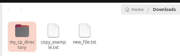
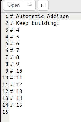
Previewing beginning of files with “head”
The “head” command is used to display the first few lines of a file.
To preview the beginning of a file, type “head” followed by the name of the file.
For example, to display the first 10 lines of a file called “head_example.txt”:
gedit head_example.txtType this inside the file:
# This is
# Automatic Addison
# Keep building!
# 4
# 5
# 6
# 7
# 8
# 9
# 10
# 11
# 12
# 13
# 14
# 15
Save the file, and close it.
head head_example.txtTo display the first 5 lines:
head -n 5 head_example.txt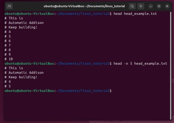
Viewing end of files with “tail”
The “tail” command is used to display the last few lines of a file.
tail head_example.txtSimilar to “head”, you can change the number of lines displayed using the “-n” option. For example, to display the last 5 lines:
tail -n 5 head_example.txt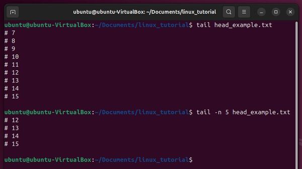
Displaying current date and time with “date”
The “date” command is used to display the current date and time.
dateThe output will show the current date and time in the default format.
You can customize the output format using format specifiers. For example, to display the date in the format “YYYY-MM-DD”, use:
date +"%Y-%m-%d"Refer to the “date” command’s manual page (“man date”) for more information on available format specifiers.
man date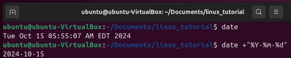
Redirecting standard output with “redirecting standard output”
In Linux, you can redirect the output of a command to a file instead of displaying it in the terminal. This is done using the “>” operator.
To redirect the output of a command to a file, type the command followed by “>” and the name of the file. For example, to redirect the output of the “ls” command to a file called “directory_contents.txt”:
cd ~/Documents/linux_tutorialls > directory_contents.txtIf the file doesn’t exist, it will be created. If the file already exists, its contents will be overwritten.
To append the output to an existing file instead of overwriting it, use the “>>” operator:
ls >> directory_contents.txtConcatenating and displaying files with “cat”
The “cat” command is used to concatenate and display the contents of files.
To display the contents of a single file, type “cat” followed by the name of the file.
cat directory_contents.txt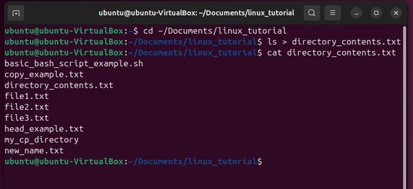
Viewing text files with “less”
The “less” command allows you to view the contents of a text file one page at a time. “less” is particularly useful for viewing large files that don’t fit on a single screen.
less head_example.txtOnce you’re in “less”, you can navigate through the file using various keyboard shortcuts:
- Press “Space” to go to the next page
- Press “b” to go back one page
- Press “q” to quit “less” and return to the terminal
Displaying text with echo
The “echo” command is used to display text or the value of variables in the terminal.
To display a simple message, type “echo” followed by the text you want to display.
For example:
echo "I am Automatic Addison"You can also use “echo” to display the value of environment variables.
For example, to display the value of the “ROS_DISTRO” variable:
echo $ROS_DISTRO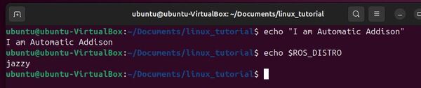
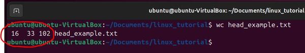
Counting words, lines, and characters with “wc”
The “wc” command is used to count the number of words, lines, and characters in a file.
wc head_example.txtThe output shows the number of lines, words, and characters in the file, in that order.
Connecting commands with piping
In Linux, you can connect multiple commands together using pipes. The output of one command becomes the input of the next command.
To use pipes, type the first command followed by the pipe symbol (“|”), then type the next command.
For example, to count the number of files in a directory:
ls | wc -lIn this example, the output of the “ls” command (the list of files) is piped to the “wc” command, which counts the number of lines (“-l” option).
You should see this as your output:
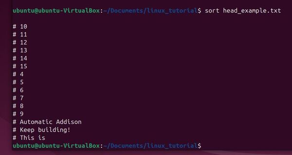
9Sorting lines of text with “sort”
The “sort” command is used to sort lines of text alphabetically or numerically.
To sort the contents of a file, type “sort” followed by the name of the file.
For example, to sort the lines in a file called “head_example.txt”:
sort head_example.txtThe output will show the sorted lines of the file.
You can also sort in reverse order.
sort -r head_example.txtNote that this sort command will not change the actual file. It will just display the sorted output in the terminal window.
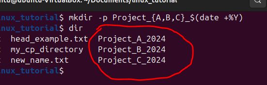
Performing shell expansions
Shell expansions are a feature that modify the way the shell interprets and executes commands.
Suppose you need to quickly create directories for three different projects each named for the current year:
mkdir -p Project_{A,B,C}_$(date +%Y)This command creates directories named Project_A_2024, Project_B_2024, and Project_C_2024 in the current directory.
dir{A,B,C} expands to create three strings: A, B, and C.
$(date +%Y) executes the date command to fetch the current year (e.g., 2024), replacing it in the command.
Comparing files line by line with “diff”
When working on projects that involve multiple versions of files, especially in a collaborative environment, it’s essential to track and understand changes between different file versions. The diff allows you to compare two files line by line and outputs the differences between them.
Let’s create a copy of this file:
cp head_example.txt head_example_copy.txtgedit head_example_copy.txtModify one of the lines in the file, and save it.
I will remove the first line “This is”.
Save the file, and close it.
To use diff, simply provide the names of the two files you want to compare:
diff head_example.txt head_example_copy.txtThis command will display the lines that differ between the two files, along with symbols that indicate whether lines were added, deleted, or changed.
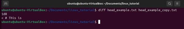
Lines prefixed with < indicate content present in the first file but not in the second.
Lines prefixed with > show content that is in the second file but not in the first.
Let’s take a closer look at our output.
“1d0” means:
- The line 1 from the first file (head_example.txt)
- Is deleted (d)
- When compared to the very beginning (before line 1) of the second file (head_example_copy.txt)
< # This is:
- This line shows the content that exists in the first file but not in the second file. The < symbol indicates that this line is from the first file.
Searching for files with “find”
The “find” command is used to search for files and directories based on various criteria such as name, size, or modification time.
To search for a file by name, type “find” followed by the directory to search in and the “-iname” option with the file name pattern.
For example, to search for a file named “head_example_copy.txt” in the Documents directory and its subdirectories:
cd ~/Documents/find . -iname "head_example_copy.txt"To find a folder named “folder1” in the current directory or its subdirectories, you can use the find command with a slight modification. Here’s the command you can use:
find . -type d -iname "folder1"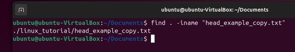
Searching text with “grep”
The “grep” command is used to search for specific text patterns within files.
To search for a text pattern in a file, type “grep” followed by the pattern and the file name.
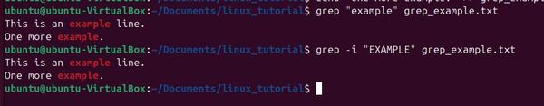
For example, to search for the word “example” in a file named “grep_example.txt”:
cd ~/Documents/linux_tutorial/echo "This is an example line." > grep_example.txtcat grep_example.txtecho "Another line here." >> grep_example.txtcat grep_example.txtecho "One more example." >> grep_example.txtcat grep_example.txtNow type:
grep "example" grep_example.txtYou can even make the search case-insensitive:
grep -i "EXAMPLE" grep_example.txtThe output will show the lines in the file that contain the search word.
Estimating file space usage with “du”
The “du” command is used to estimate the disk space used by files and directories.
To display the disk space used by a specific file or directory, type “du” followed by the file or directory name.
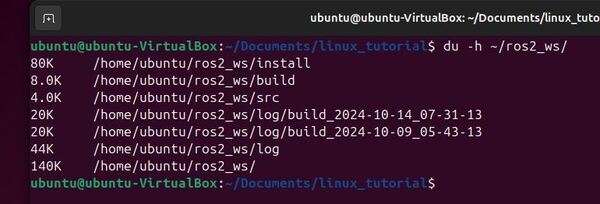
For example:
du -h ~/ros2_ws/The output will show the disk space used by each file and subdirectory within “my_directory”, as well as the total disk space used by the directory.
Displaying filesystem space usage with “df”
The “df” command is used to display information about the disk space usage of filesystems.
To display the disk space usage of all mounted filesystems, simply type “df”:
df -h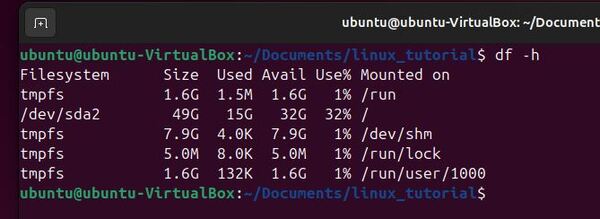
Viewing command history with “history”
The “history” command is used to display a list of previously executed commands in the current shell session.
To view the command history, type “history”:
history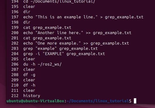
Displaying process status with “ps”
The “ps” command is used to display information about running processes.
To display the processes associated with the current shell session, type “ps”:
psThe output will show the process ID (PID), terminal, CPU time, and command name for each process.
To display all processes running on the system, use the “-e” option:
ps -e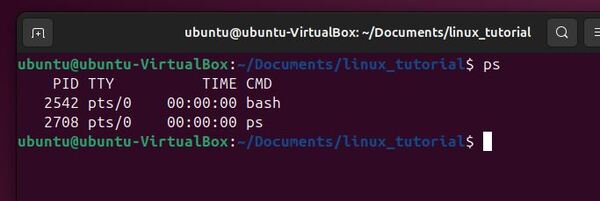
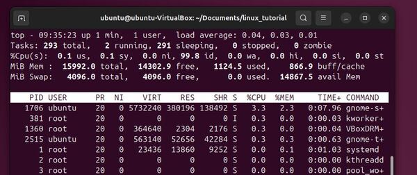
Displaying system resource usage with “top”
The “top” command is used to display real-time information about system resource usage and running processes.
To start “top”, simply type “top”:
topPress “q” to quit “top”
Press “M” to sort processes by memory usage (i.e. Shift + M)
Press “P” to sort processes by CPU usage (i.e. Shift + P)
Terminating processes with “kill” and “killall”
The “kill” command is used to send a signal to a process, typically to terminate it, while the “killall” command is used to send a signal to all processes with a specified name.
To terminate a process with “kill”, type “kill” followed by the process ID (PID). For example, to terminate a process with PID 1234:
kill 1234To terminate all processes with a specific name using “killall”, type “killall” followed by the process name. For example, to terminate all processes named “firefox”:
Start firefox.
firefoxCheck out the processes:
topClose firefox.
killall firefoxDisplay background processes with “jobs”
The “jobs” command is used to display a list of background processes started by the current shell session, while the “bg” and “fg” commands are used to manage these processes.
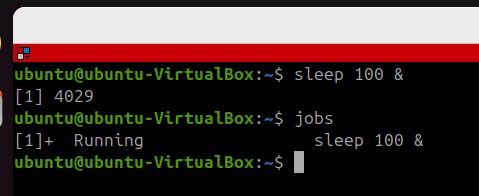
To start a process in the background, append an ampersand (“&”) to the end of the command.
For example, let’s start the sleep command as a background process:
<command> &
Becomes:
sleep 100 &To list the background processes, type “jobs”:
jobsEach process will be displayed with a job number and its status (e.g., “Running” or “Stopped”).
Managing background processes with “bg,” and “fg”
To bring a background process to the foreground, type “fg” followed by the job number.
For example, to bring job 1 to the foreground:
fg %1To send a foreground process to the background, press “Ctrl+Z” to suspend it, then type “bg” to resume it in the background:
bg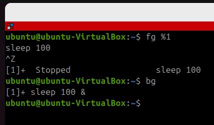
Compressing files with “gzip”
The “gzip” command is used to compress files to reduce their size.
To compress a file, type “gzip” followed by the file name.
For example, to compress a file named “grep_example.txt”:
cd ~/Documents/linux_tutorialtouch grep_example.txtgzip -k grep_example.txtdirThe compressed file will have the extension “.gz” added to its name, e.g., “grep_example.txt.gz”.
dir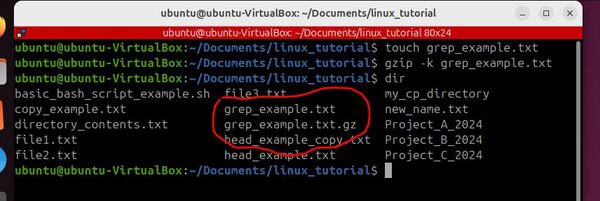
Decompressing files with “gunzip”
The “gunzip” command is used to decompress files that were compressed with “gzip”.
To decompress a file, type “gunzip” followed by the file name.
For example, to decompress a file named “grep_example.txt.gz”:
gunzip -k grep_example.txt.gzThe decompressed file will have the “.gz” extension removed from its name.

Archiving and extracting files with “tar”
The “tar” command is used to create and extract archive files, which are collections of multiple files and directories combined into a single file.
For example, to create an archive named “archive.tar” containing the files “file1.txt” and “file2.txt”:
touch tar_example_file1.txt tar_example_file2.txttar cf archive.tar tar_example_file1.txt tar_example_file2.txtdir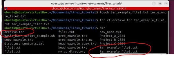
Now remove the files:
rm tar_example_file1.txt tar_example_file2.txt To extract the contents of a tar archive, type “tar” followed by the “xf” options and the archive file name.
For example, to extract the contents of an archive named “archive.tar”:
tar xf archive.tarThe files and directories will be extracted into the current directory.
Building and executing commands with “xargs”
The “xargs” command is used to build and execute commands from standard input.
A common use case for “xargs” is to pass the output of one command as arguments to another command.
Let’s create a test environment for this command:
mkdir xargs_test && cd xargs_testtouch file1.txt file2.txt file3.txtUse xargs to list file contents:
echo file1.txt file2.txt file3.txt | xargs catAdd content to files:
echo "Hello" > file1.txtecho "World" > file2.txtecho "Xargs" > file3.txtRun the command again:
echo file1.txt file2.txt file3.txt | xargs cat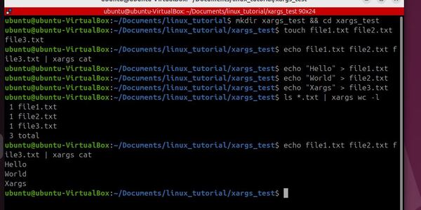
This basic demonstrates how xargs takes input from one command and uses it as arguments for another.
Now let’s go back to the previous directory.
cd ..Creating symbolic links with “ln”
The “ln” command is used to create links between files. There are two types of links: hard links and symbolic (soft) links.
To create a symbolic link, type “ln” with the “-s” option, followed by the source file and the link name.
For example:
touch symbolic_link_example.txtln -s symbolic_link_example.txt my_test_linkThe symbolic link “my_test_link” will point to “symbolic_link_example.txt”.
When you access “my_test_link”, it will redirect you to the contents of “symbolic_link_example.txt”.
Symbolic links can point to files or directories on different filesystems, and they will continue to work even if the source file is moved or deleted.
Now let’s test this symbolic link by adding some text to the original file:
echo "Hello, World!" > symbolic_link_example.txtcat my_test_link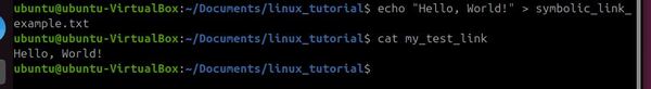
Replacing Words with “sed”
The “sed” command is used to modify text in a file or input stream. You can use “sed” to replace occurrences of a word or phrase with another:
cd ~/Documents/linux_tutorialecho "The old_word is here. Another old_word is there." > test.txtcat test.txtsed -i 's/old_word/new_word/g' test.txtcat test.txt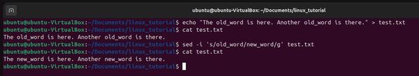
Executing commands with superuser privileges with “sudo”
The “sudo” command is used to execute commands with superuser (root) privileges.
To execute a command with superuser privileges, type “sudo” followed by the command.
For example, to update the package list on an Ubuntu system:
sudo apt-get updateYou will be prompted to enter your user password. Once authenticated, the command will run with superuser privileges.
The “sudo” command grants temporary superuser privileges for a single command, without the need to switch to the root account.
Changing user password with “passwd”
The “passwd” command is used to change a user’s password.
To change your own password, simply type “passwd”:
passwdYou will be prompted to enter your current password, then prompted to enter and confirm the new password.
Modifying file ownership with “chown”
To demonstrate the use of chown, let’s create a test file:
cd ~/Documents/linux_tutorialtouch chown_example.txtTo see the current owner of the file, use the ls command with the -l option:
ls -l chown_example.txtTo change the owner of a file, use “chown” followed by the new owner and the file name.
For example, to change the owner of “chown_example.txt” to root:
sudo chown root chown_example.txtYou’ll be prompted for your password. After entering it, check the new ownership:
ls -l chown_example.txt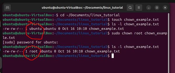
We’ve learned many important Linux commands for robotics in this tutorial.
I hope this guide helps you feel more confident using Linux, and remember, all great roboticists started as beginners too – so keep practicing, stay curious, and enjoy your robotics journey.
Keep building!