In this section, we will develop our first ROS application. We are not going to do anything fancy here…just a basic “Hello World” project to get our feet wet with ROS. But before we get started on that, let’s cover some basic ROS terminology on a high level.
You Will Need
In order to complete this tutorial, you will need:
Directions
Our goal in this project is to get two pieces of ROS software (called nodes) to talk to each other. You can think of nodes as small single-purpose programs within a larger robotic system. One way nodes communicate with each other is by using messages. These messages are passed via channels called topics.
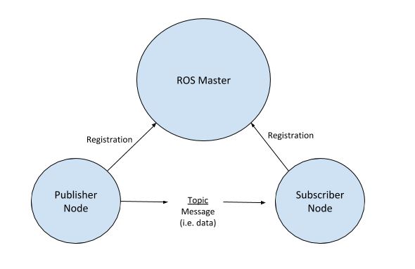
Nodes that send data are known as publisher nodes, and nodes that receive data are known as subscriber nodes. The node that keeps track (i.e. a register) of which nodes are publisher nodes and which nodes are subscriber nodes is called the ROS Master. Without the ROS Master, nodes would not be able to communicate with each other.
Nodes that are interested in a particular piece of data subscribe to the relevant topic; nodes that generate data publish to the relevant topic. There can be multiple publishers and subscribers to a topic. You can think of topics like a middle man between publishers (nodes that generate data) and subscribers (nodes that receive data). The communication is anonymous, so nodes do not know what nodes they are sending data to/receiving data from.
Here is a basic high-level diagram of the ROS Topic communication architecture I described above.
A good analogy is to think of YouTube (or even other social media sites like Twitter or Instagram). YouTubers (publisher nodes) publish videos (messages) to a channel (topic), and you (subscriber node) can subscribe to that channel (topic) so that you receive all the videos (messages) on that channel (topic). YouTube (ROS Master) keeps track of who is a publisher and who is a subscriber. One thing to keep in mind is that (in contrast to YouTube) in ROS there can be multiple publishers to the same topic, and publishers and subscribers don’t know each other.
In the robotic world, we need different parts of a robot to send data to each other so that the robot can sense the world, process what it sees, and then act on the world. For example, suppose we are working on a humanoid robot. We might have one small program (publisher node) responsible for reading sensor data from a camera mounted on the head of the robot. That program might send that data (i.e. message) via a topic called “vision scan” to another program (subscriber node) which is responsible for controlling the joint in the robot’s arm. Note that messages in ROS can be a variety of data types, including strings, floats, integers, etc.
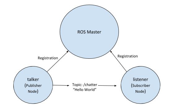
So with that terminology under our belts, we are ready to get started on our Hello World project. Let’s develop an application that consists of two nodes: talker and listener. The talker node will publish a “Hello World” message to the /chatter topic. The listener will subscribe to the /chatter topic so that it can receive the “Hello World” message. Here is a diagram of what I described above.
To launch ROS, open a new Linux terminal window and type the following command:
roscore
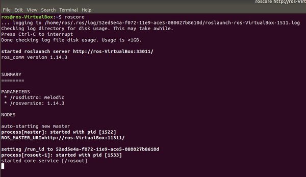
roscore is the main process that is responsible for managing everything in ROS. Anytime you are trying to run a program in ROS, roscore needs to be running. roscore ensures that nodes (i.e. programs you write in Python and C++) are able to communicate with each other.
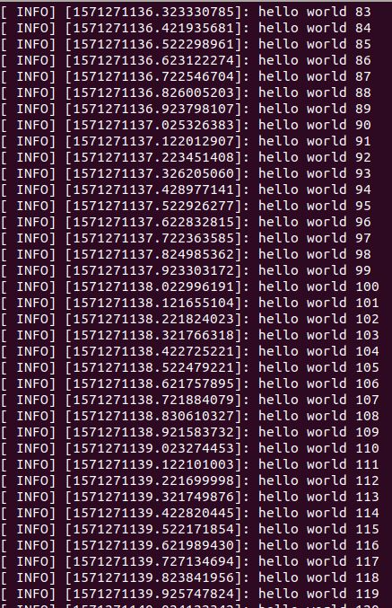
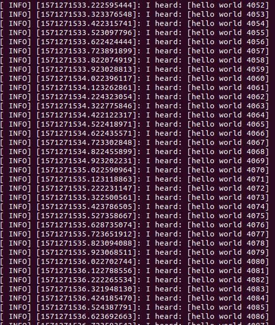
Open up a new terminal window, and start the talker node.
rosrun roscpp_tutorials talker
You should see hello world messages repeatedly printing to the screen.
Use this command on a new terminal tab (File -> New Tab) to see a list of current active topics.
rostopic list
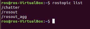
The topic of the hello world messages is /chatter.
Now let’s start the listener node. The listener node will subscribe to the /chatter topic so that it can receive the hello world messages published by talker.
Open up a new terminal tab and type:
rosrun roscpp_tutorials listener
The listener “hears” hello world.
Now, let’s run the two nodes side-by-side just to see what that looks like. Open a new terminal tab and type:
roslaunch roscpp_tutorials talker_listener.launch
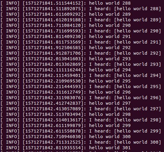
The roslaunch command is useful when you want to launch multiple ROS nodes all at once.
To stop ROS, press this command on your keyboard:
Ctrl+C
Then type the following command in the terminal to close the terminal.
exit
That’s it! Congrats! You have made your first ROS application.