In this tutorial, you will learn how to draw a contour around an object.
Prerequisites
- You have Python 3.7 or higher
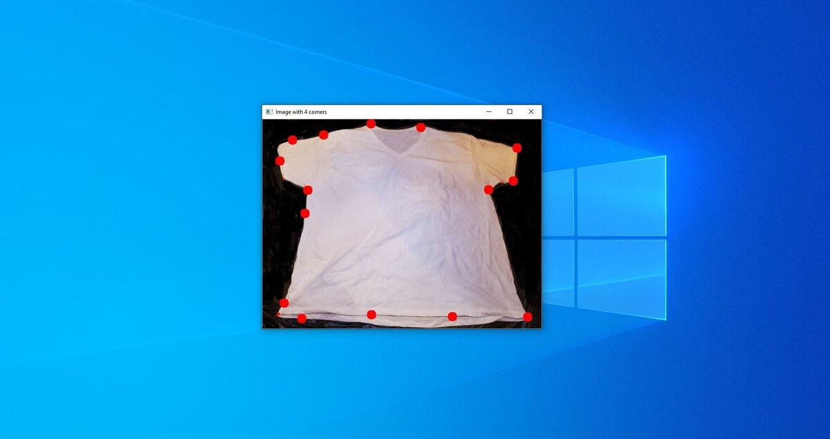
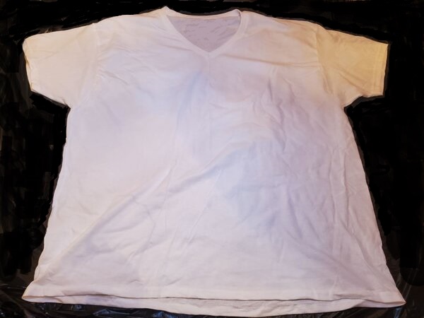
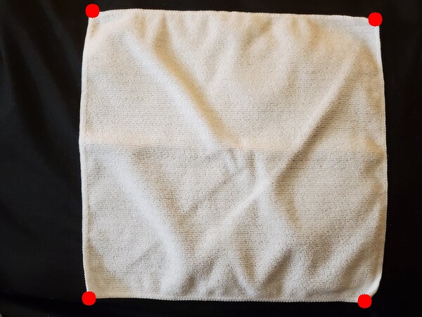
Draw a Contour Around a T-Shirt

We’ll start with this t-shirt above. Save that image to some folder on your computer.
Now, in the same folder you saved that image above (we’ll call the file tshirt.jpg), open up a new Python program.
Name the program draw_contour.py.
Write the following code:
# Project: How To Draw Contours Around Objects Using OpenCV
# Author: Addison Sears-Collins
# Date created: October 7, 2020
# Reference: https://stackoverflow.com/questions/58405171/how-to-find-the-extreme-corner-point-in-image
import cv2 # OpenCV library
import numpy as np # NumPy scientific computing library
# Read the image
image = cv2.imread("tshirt.jpg")
# Convert the image to grayscale
gray = cv2.cvtColor(image, cv2.COLOR_BGR2GRAY)
# Convert the image to black and white.
# Modify the threshold (e.g. 75 for tshirt.jpg) accordingly depending on how to output looks.
# If you have a dark item on a light background, use cv2.THRESH_BINARY_INV and consider
# changing the lower color threshold to 115.
thresh = cv2.threshold(gray, 75, 255, cv2.THRESH_BINARY)[1]
#thresh = cv2.threshold(gray, 115, 255, cv2.THRESH_BINARY_INV)[1]
# Create a kernel (i.e. a small matrix)
kernel = np.ones((5,5),np.uint8)
# Use the kernel to perform morphological opening
thresh = cv2.morphologyEx(thresh, cv2.MORPH_OPEN, kernel)
# If you have a dark item on a light background, uncomment this line.
#thresh = cv2.morphologyEx(thresh, cv2.MORPH_CLOSE, kernel)
# Find the contours
cnts = cv2.findContours(thresh, cv2.RETR_EXTERNAL, cv2.CHAIN_APPROX_SIMPLE)
cnts = cnts[0] if len(cnts) == 2 else cnts[1]
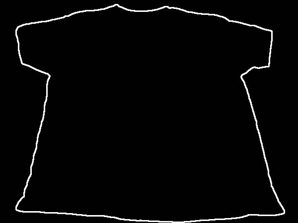
# Create a blank image
blank_image = np.ones((450,600,3), np.uint8)
# Set the minimum area for a contour
min_area = 5000
# Draw the contours on the original image and the blank image
for c in cnts:
area = cv2.contourArea(c)
if area > min_area:
cv2.drawContours(image,[c], 0, (36,255,12), 2)
cv2.drawContours(blank_image,[c], 0, (255,255,255), 2)
# Conver the blank image to grayscale for corner detection
gray = cv2.cvtColor(blank_image, cv2.COLOR_BGR2GRAY)
# Detect corners using the contours
corners = cv2.goodFeaturesToTrack(image=gray,maxCorners=25,qualityLevel=0.20,minDistance=50) # Determines strong corners on an image
# Draw the corners on the original image
for corner in corners:
x,y = corner.ravel()
cv2.circle(image,(x,y),10,(0,0,255),-1)
# Display the image
image_copy = cv2.imread("tshirt.jpg")
cv2.imshow('original image', image_copy)
cv2.imshow('image with contours and corners', image)
cv2.imshow('blank_image with contours', blank_image)
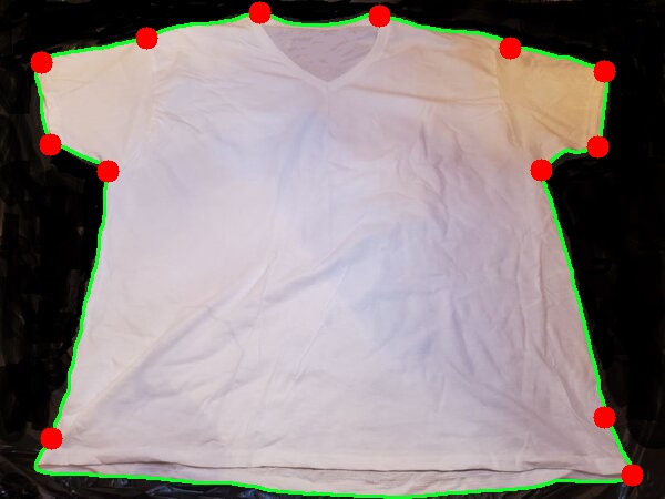
# Save the image that has the contours and corners
cv2.imwrite('contour_tshirt.jpg', image)
# Save the image that has just the contours
cv2.imwrite('contour_tshirt_blank_image.jpg', blank_image)
# Exit OpenCV
if cv2.waitKey(0) & 0xff == 27:
cv2.destroyAllWindows()
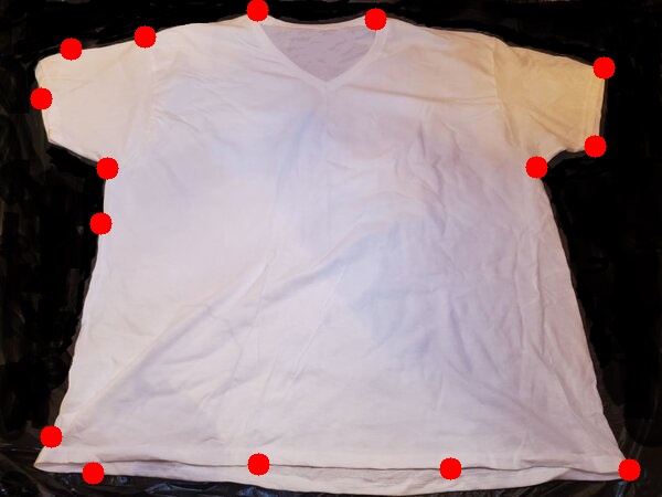
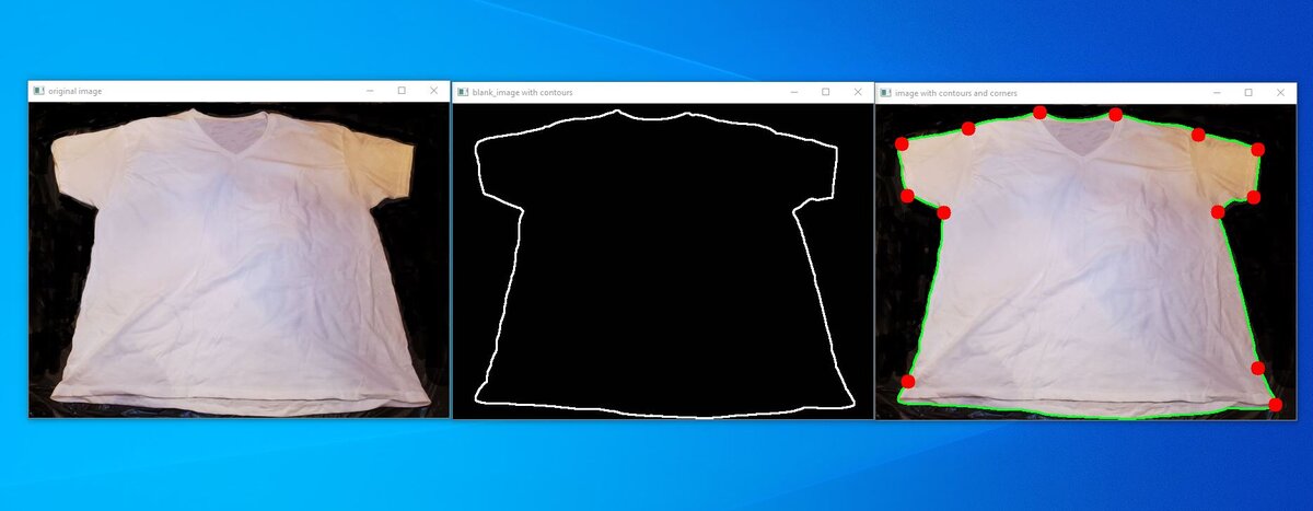
Run the code. Here is what you should see:
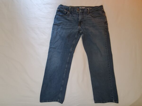
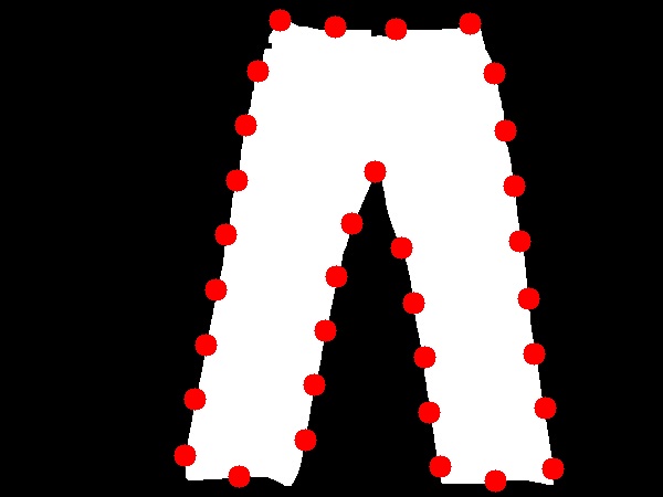
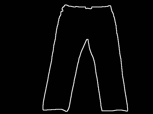
Detecting Corners on Jeans
To detect corners on jeans, you’ll need to make the changes mentioned in the code. This is because the jeans are a dark object on a light background (in contrast to a light object on a dark background in the case of the t-shirt).
Let’s draw a contour around the pair of jeans.
Here is the input image (jeans.jpg):

Change the fileName variable in your code so that it is assigned the name of the image (‘jeans.jpg’).
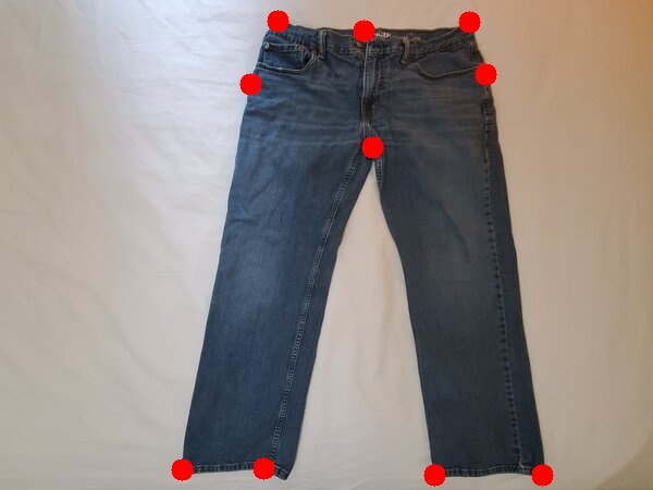
Here is the output image:

That’s it. Keep building!