In this tutorial, we’ll dive into the world of coordinate frames, the backbone of mobile robot navigation using ROS 2.
Imagine you’re a robot trying to move around in a room. To do that effectively, you need to understand where you are, where your sensors are, and how to translate the information they provide into a format you can use to navigate safely. That’s where coordinate transformations come in.
Different sensors (like LIDAR, cameras, and IMUs) provide data in their own coordinate frames. Coordinate transformations convert this data into a common frame, usually the robot base frame, making it easier to process and use for navigation.
If you prefer learning by video, watch the video below, which covers this entire tutorial from start to finish.
Prerequisites
- You have completed this tutorial: How to Install ROS 2 Navigation (Nav2) – ROS 2 Jazzy.
All my code for this project is located here on GitHub.
Why Coordinate Transformations Are Important
Why are coordinate transformations so important? Well, think about it like this: your robot is like a person with two “eyes”: a LIDAR and a depth camera. The LIDAR measures distances to objects, while the depth camera provides a 3D image of the environment.
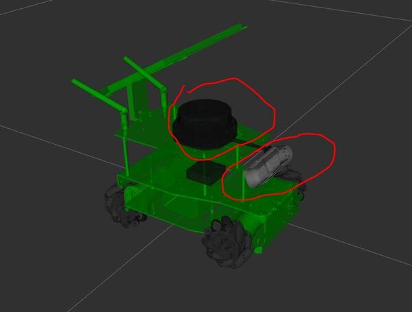
These sensors are located at different positions on the robot, so they have different perspectives.
To navigate safely in the world, the robot needs to combine the obstacle detection information from both sensors into a common understanding of its surroundings. This is where coordinate transformations come in. They act as a translator, converting the information from each sensor’s unique perspective into a shared language – the robot’s base coordinate frame.
By expressing the LIDAR and depth camera data in the same coordinate frame, the robot can effectively merge the information and create a unified obstacle map of its environment. This allows the robot to plan paths and avoid obstacles, taking into account its own dimensions and the location of objects detected by both sensors.
In essence, coordinate transformations enable the robot to make sense of the world by unifying the different perspectives of its sensors.
Launch the Mobile Robot
Let’s bring your robot to life. Open a terminal window, and type the following command:
x3 or
bash ~/ros2_ws/src/yahboom_rosmaster/yahboom_rosmaster_bringup/scripts/rosmaster_x3_gazebo.shYou should now see your robot in Gazebo as well as RViz.
Visualize the Coordinate Frames
Let’s take a look at the coordinate frames.
In RViz, find the Displays panel on the left-hand side.
Untick the “Robot Model” so that you only see the coordinate frames.
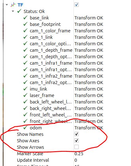
In the TF dropdown menu, tick “Show Axes” and “Show Names”.
These frames are 3D coordinate systems that define the position and orientation of different parts of your robot.
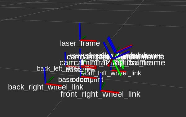
Each part of the robot, such as the base, LIDAR, or depth camera, has its own coordinate frame. A coordinate frame consists of three perpendicular axes. By convention:
- The red arrows represent the x axes
- The green arrows represent the y axes.
- The blue arrows represent the z axes.
The origin of each coordinate frame is the point where all three axes intersect.
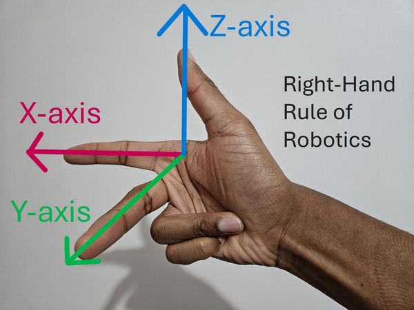
Right-Hand Rule of Robotics
The right-hand rule is a helpful method to remember the orientation of these axes:
- Take your right hand and point your index finger forward. That represents the x-axis (red).
- Now point your middle finger to the left. That represents the y-axis (green).
- Point your thumb towards the sky. Your thumb represents the z-axis (blue).
Visualize the Coordinate Frames
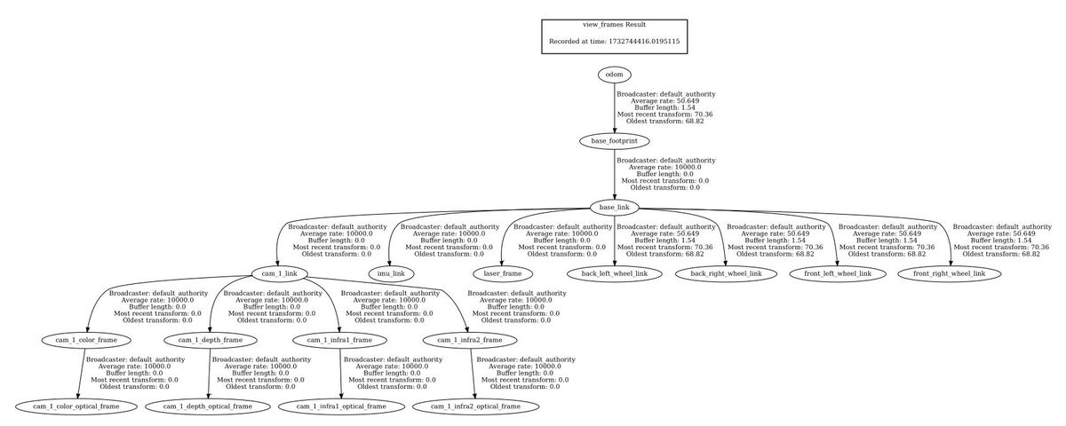
As a friendly reminder, if you ever want to see the hierarchy of the coordinate frames for your robot in a PDF file, you can do this.
Open a terminal window, and move to any directory. I will move to my Downloads folder.
cd ~/Downloads/
Type this command:
ros2 run tf2_tools view_frames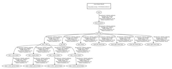
In the current working directory, you will have a file called frames_20XX.pdf. Open that file.
evince frames_20XX.pdfIn my case, I will type:
evince frames_2024-11-27_16.53.36.pdfYou can see all your coordinate frames.
Coordinate Transformations in Nav2
How Nav2 Uses Coordinate Frames
The Nav2 package for ROS 2 makes extensive use of coordinate transformations to enable a robot to navigate autonomously through an environment. It uses coordinate transformations not just for obstacle detection, but also localization.
Imagine your robot as a character in a video game. Just like how the game keeps track of the character’s position in the game world, Nav2 uses coordinate transformations to keep track of the robot’s position in the real world.
ROS Enhancement Proposals (REPs) Relevant to Nav2
When it comes to configuring your robot for autonomous navigation, ROS has some guidelines to make sure everyone’s robots can play nicely with Nav2. These guidelines are called “REP,” which stands for “ROS Enhancement Proposals.”
Two important REPs for Nav2 are:
1. REP 105: This guideline explains how to name and describe the different coordinate frames (think of them as different perspectives) for mobile robots.
2. REP 103: This guideline talks about using standard units of measurement (like meters for distance) and following certain rules for describing positions and orientations.
Nav2 follows these guidelines to ensure it can work well with other ROS packages.
Key Coordinate Frames in Nav2
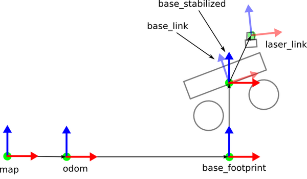
The four most important coordinate frames in Nav2 are as follows:
- base_link
- The base_link is usually the center point of your robot’s base. No matter how much the robot moves or turns, the base_link stays put, and is the unifying reference point for the car’s movement and sensors.
- base_footprint
- This coordinate frame is a projection of the base_link frame onto the ground plane. Nav2 uses the base_footprint link to determine the robot’s position relative to the ground and nearby obstacles.
- odom:
- The odom frame is the robot’s “starting point.” Think of the odom frame like the odometer on your car that measures the distance the car has traveled from some starting point.
- The odom frame in Nav2 keeps track of the robot’s position and orientation relative to its starting position and orientation. The data from the odom frame is usually based on wheel encoders or other sensors.
- Like an odometer for your car, the odom frame can drift over time due to small errors accumulating (e.g. slippage of the wheels), making it unreliable for making a long-term estimate of how far the robot has traveled and which way the robot is turned.
- map:
- The map frame provides a global, long-term reference for the robot’s position and orientation in an environment. It is constantly updated by a localization system that uses sensor data to correct any drift in the robot’s estimated position.
- The map frame is like a car’s GPS system. It shows the car’s location on a global map, ensuring that the car’s position remains accurate over long distances. However, just like a GPS update, the robot’s position in the map frame can sometimes jump suddenly when the localization system makes corrections.
Key Coordinate Transformations in Nav2
For Nav2 to do its job, it needs to know how these coordinate frames relate to each other. Nav2 requires the following specific transformations between coordinate frames to be published over ROS 2:
- map => odom: This transform connects the global map frame to the robot’s odometry frame. It’s usually provided by a localization or mapping package such as AMCL, which continuously updates the robot’s estimated position in the map.
- odom => base_link: This transform relates the robot’s odometry frame to its base frame. It’s typically published by the robot’s odometry system, which combines data from sensors like wheel encoders and IMUs using packages like robot_localization. We will see how to do this in a future tutorial.
- base_link => sensor_frames: These transforms describe the relationship between the robot’s base frame and its sensor frames, such as laser_frame for your LIDAR. If your robot has multiple sensors, each sensor frame needs a transform to the base_link frame.
Publishing Transforms in Nav2
To provide the necessary transforms to Nav2, you’ll typically use two methods:
- Static Transforms: These are fixed transforms that define the relationship between the robot’s base and its sensors. They are usually specified in the robot’s URDF file and published by the Robot State Publisher package.
- Dynamic Transforms: These transforms change over time, like the map => odom transform, which is updated as the robot moves through the environment. Dynamic transforms are usually published by packages responsible for localization, mapping, or odometry.
Why Transformations Matter in Nav2
Transformations are important for several aspects of Nav2’s functionality:
- Localization: By combining sensor data with transform information, Nav2 can estimate the robot’s pose (position and orientation) in the environment.
- Path Planning: Nav2’s path planner uses transforms to create a path from the robot’s current position to its goal in the map frame. The planned path is then transformed into the robot’s base frame for execution.
- Recovery Behaviors: When the robot encounters issues during navigation, Nav2’s recovery behaviors use transform information to help the robot get back on track.
In summary, transformations help the robot understand its surroundings, keep track of its position, and navigate safely. By following ROS guidelines and managing these transforms, Nav2 ensures your robot can explore the world with ease.
That’s it for the theory. In the next tutorials, you will get hands-on practice with these concepts.
Keep building!

