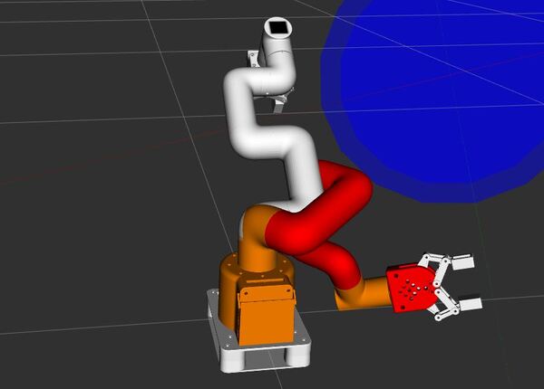
In this tutorial, we will create a basic “Hello World” project to get your feet wet with C++ and MoveIt 2. I will show you how to move the end of the robotic arm (where the gripper is located) to a desired position and orientation.
The official instructions are on this page, but we will walk through everything together, step by step.
If you prefer to learn by video instead of reading this wall of text below, please check out this video:
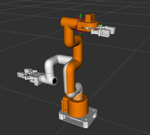
By the end of this tutorial, you will be able to create this:
This command creates a new package named “mycobot_moveit_demos” with the necessary dependencies and a node named “hello_moveit”. The package will be created inside the mycobot_ros2 directory.
Next, let’s move into our newly created package:
cd mycobot_moveit_demos
Create a ROS Node
Now that we have our package in place, let’s set up our C++ file to work with MoveIt 2. We’ll start by editing the main source file.
Open the new source code file you created.
cd src
Open hello_moveit.cpp.
Add this code:
/**
 * @file hello_moveit.cpp
 * @brief A basic ROS 2 and MoveIt 2 program to control a robot arm
 *
 * This program demonstrates how to use ROS 2 and MoveIt 2 to control a robot arm.
 * It sets up a node, creates a MoveGroupInterface for the arm, sets a target pose for the gripper_base,
 * plans a trajectory, and executes the planned motion.
 *
 * @author Addison Sears-Collins
 * @date December 15, 2024
 */

#include <geometry_msgs/msg/pose_stamped.hpp>
#include <memory>
#include <rclcpp/rclcpp.hpp>
#include <moveit/move_group_interface/move_group_interface.h>

/**
 * @brief The main function that starts our program.
 *
 * This function sets up our ROS 2 environment and prepares it for robot control.
 *
 * @param argc The number of input arguments our program receives.
 * @param argv The list of input arguments our program receives.
 * @return int A number indicating if our program finished successfully (0) or not.
 */
int main(int argc, char * argv[])
{
  // Start up ROS 2
  rclcpp::init(argc, argv);

  // Creates a node named "hello_moveit". The node is set up to automatically
  // handle any settings (parameters) we might want to change later without editing the code.
  auto const node = std::make_shared<rclcpp::Node>(
    "hello_moveit",
    rclcpp::NodeOptions().automatically_declare_parameters_from_overrides(true)
  );

  // Creates a "logger" that we can use to print out information or error messages
  // as our program runs.
  auto const logger = rclcpp::get_logger("hello_moveit");

  // Create the MoveIt MoveGroup Interfaces
  // These interfaces are used to plan and execute movements, set target poses,
  // and perform other motion-related tasks for each respective part of the robot.
  // The use of auto allows the compiler to automatically deduce the type of variable.
  // Source: https://github.com/moveit/moveit2/blob/main/moveit_ros/planning_interface/move_group_interface/include/moveit/move_group_interface/move_group_interface.h
  using moveit::planning_interface::MoveGroupInterface;
  auto arm_group_interface = MoveGroupInterface(node, "arm");

  // Specify a planning pipeline to be used for further planning
  arm_group_interface.setPlanningPipelineId("ompl");

  // Specify a planner to be used for further planning
  arm_group_interface.setPlannerId("RRTConnectkConfigDefault");

  // Specify the maximum amount of time in seconds to use when planning
  arm_group_interface.setPlanningTime(1.0);

  // Set a scaling factor for optionally reducing the maximum joint velocity. Allowed values are in (0,1].
  arm_group_interface.setMaxVelocityScalingFactor(1.0);

  //  Set a scaling factor for optionally reducing the maximum joint acceleration. Allowed values are in (0,1].
  arm_group_interface.setMaxAccelerationScalingFactor(1.0);

  // Display helpful logging messages on the terminal
  RCLCPP_INFO(logger, "Planning pipeline: %s", arm_group_interface.getPlanningPipelineId().c_str());
  RCLCPP_INFO(logger, "Planner ID: %s", arm_group_interface.getPlannerId().c_str());
  RCLCPP_INFO(logger, "Planning time: %.2f", arm_group_interface.getPlanningTime());

  // Set a target pose for the end effector of the arm
  auto const arm_target_pose = [&node]{
    geometry_msgs::msg::PoseStamped msg;
    msg.header.frame_id = "base_link";
    msg.header.stamp = node->now();
    msg.pose.position.x = 0.061;
    msg.pose.position.y = -0.176;
    msg.pose.position.z = 0.168;
    msg.pose.orientation.x = 1.0;
    msg.pose.orientation.y = 0.0;
    msg.pose.orientation.z = 0.0;
    msg.pose.orientation.w = 0.0;
    return msg;
  }();
  arm_group_interface.setPoseTarget(arm_target_pose);

  // Create a plan to that target pose
  // This will give us two things:
  // 1. Whether the planning was successful (stored in 'success')
  // 2. The actual motion plan (stored in 'plan')
  auto const [success, plan] = [&arm_group_interface] {
    moveit::planning_interface::MoveGroupInterface::Plan msg;
    auto const ok = static_cast<bool>(arm_group_interface.plan(msg));
    return std::make_pair(ok, msg);
  }();

  // Try to execute the movement plan if it was created successfully
  // If the plan wasn't successful, report an error
  // Execute the plan
  if (success)
  {
    arm_group_interface.execute(plan);
  }
    else
  {
    RCLCPP_ERROR(logger, "Planning failed!");
  }

  // Shut down ROS 2 cleanly when we're done
  rclcpp::shutdown();
  return 0;
}
This code does the following:
Executes the plan if it was successful, or logs an error if planning failed.
Sets a target pose for the end effector (gripper_base) of the robotic arm.
Plans a path to reach that target pose.
Let’s compile our code to make sure everything is set up correctly. Go back to your workspace directory:
cd ~/ros2_ws
To build the package with debug information, we’ll use the following command:
In another terminal, run your program to move the robotic arm from one place to another:
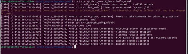
ros2 run mycobot_moveit_demos hello_moveit
You can safely ignore this warning:
[WARN] [1734267864.788892796] [moveit_2886993382.moveit.ros.robot_model_loader]: No kinematics plugins defined. Fill and load kinematics.yaml!
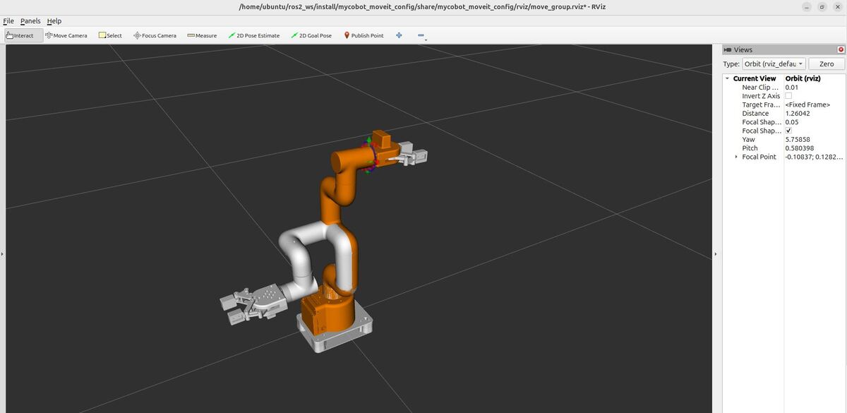
If everything is set up correctly, you should see the robot move in RViz to the specified pose.
You can confirm the gripper is in the correct pose by typing the following command and comparing it to the pose you set in your hello_moveit.cpp file.
ros2 run tf2_ros tf2_echo base_link gripper_base
Note: If you run the hello_moveit node without first launching the demo launch file, it will wait for 10 seconds and then exit with an error message. This is because the MoveGroupInterface looks for a node publishing the robot description topic, which is provided by the demo launch file.
Let’s break down the key components of our hello_moveit.cpp file to understand how it works with MoveIt 2 for controlling the arm.
MoveGroupInterface Creation:
This part sets up a control interface for the robot’s arm. It’s like creating a special remote control that lets us send commands to move the arm.
Setting the Target Pose:
Here, we’re telling the arm where we want it to go.
Planning the Motion:
This is where the robot figures out how to move from its current position to the target we set. It’s like planning a route on a map – the robot calculates all the steps needed to get from point A to point B safely.
Executing the Plan:
Finally, if the planning was successful, we tell the robot to actually perform the movement we planned. If the planning failed for some reason, we just report an error instead of trying to move.
These steps work together to allow us to control the robot arm in a safe and precise manner, moving it to exactly where we want it to go.
In the previous tutorial, you learned how to leverage ROS 2 Control to move the robotic arm manually by sending raw joint commands to the robot. This exercise is great for learning, but it is not how things are done in a real-world robotics project.
In this tutorial, I will show you how to set up a ROS 2 software called MoveIt 2 to send those commands. MoveIt 2 is a powerful and flexible motion planning framework for robotic manipulators.
Using MoveIt 2 instead of sending manual commands through a terminal window allows for more sophisticated, efficient, and safer motion planning, taking into account obstacles, joint limits, and other constraints automatically.
By the end of this tutorial, you will be able to create this:
If you prefer to learn by video instead of reading this wall of text below, please check out this video:
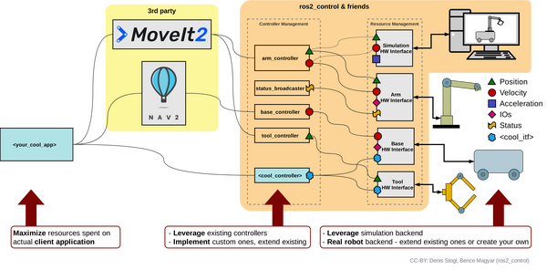
Before we dive into the tutorial, let me explain how MoveIt 2 works with ROS 2 Control by walking through a common real-world use case.
Suppose you have a mobile manipulator, which consists of a wheeled robot base with a robotic arm attached to it.
You want to develop an application that performs a pick and place task.
Your cool app starts by telling MoveIt 2, “Pick up the object at location A and place it at location B.”
MoveIt 2, with help from Nav 2 (the navigation software stack for ROS 2), plans out the detailed movements needed – reaching for the object, grasping it, lifting it, moving to the new location, and placing it down.
These plans are sent to ROS 2 Control’s Controller Management system, which has specific controllers for the arm, gripper, and base.
The arm controller (e.g. JointTrajectoryController), for example, breaks down the plan into specific joint movements and sends these to the Resource Management system.
The Resource Management system communicates these commands through hardware interfaces to the actual robot parts (or their simulated versions).
As the robot executes the pick and place task, sensors in its joints and gripper send back information about position, force, and status.
This feedback flows back up through the system, allowing your app and MoveIt 2 to monitor progress and make adjustments if needed.
This setup allows you to focus on defining high-level tasks while MoveIt 2 and ROS 2 Control handle the complex details of robot control and movement coordination.
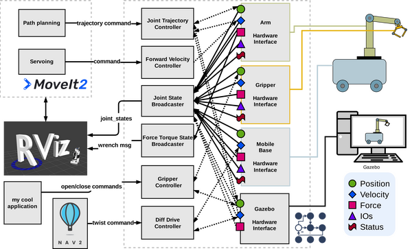
Now let’s look at another diagram which shows the specific controller and topic names. This gives us a more detailed view of how MoveIt 2, ROS 2 Control, and the robot components interact:
Your cool application initiates the process, defining tasks like pick and place operations.
MoveIt 2 contains a path planning component that generates trajectory commands. These commands are sent to the Joint Trajectory Controller, which manages the arm’s movements.
For mobile robots, Nav 2 can send twist commands to the Diff Drive Controller, controlling the base’s motion.
The system includes several specialized controllers:
Joint Trajectory Controller for arm movements
Forward Velocity Controller for speed control (optional…only needed if you need direct velocity control for high-speed operations)
Gripper Controller for end-effector actions (e.g. open and close gripper)
Diff Drive Controller for mobile base navigation
These controllers communicate with Hardware Interfaces for the arm, gripper, mobile base, and the Gazebo simulation.
As the robot operates, sensor data flows back through these Hardware Interfaces. This information includes position, velocity, force, and status updates.
The Joint State Broadcaster and Force Torque State Broadcaster collect this feedback data.
This state information (e.g. joint angles) is then forwarded to RViz for visualization and to MoveIt 2 for real-time monitoring and adjustment.
Update package.xml
Now that you understand how all the pieces work together on a high level, let’s start setting up our robot with MoveIt 2.
Create a new package called mycobot_moveit_config:
cd ~/ros2_ws/src/mycobot_ros2/mycobot_moveit_config
Type in your password, and install any missing dependencies.
Now build.
colcon build && source ~/.bashrc
In a real robotics project, the naming convention for this package would be:
<robot_name>_moveit_config
Create the Configuration Files
Let’s create configuration files that will enable us to tailor our robot for MoveIt 2. We’ll do this process manually (recommended), but you are welcome to use the MoveIt Setup Assistant.
MoveIt 2 requires configuration files to go into the config folder of the package.
Open a terminal window, and type:
cd ~/ros2_ws/src/mycobot_ros2/mycobot_moveit_config/config/mycobot_280
Add SRDF
The first thing we need to do is set up the SRDF File.
Semantic Robot Description Format (SRDF) is a file that tells MoveIt how your robot prefers to move and interact with its environment. It is a supplement to the URDF file.
The SRDF adds semantic (meaning-based) information to the robot’s description that isn’t included in the URDF (Unified Robot Description Format). This file includes things like:
Naming groups of joints or links (e.g., “arm”, “gripper”)
Which parts of the robot should be checked for colliding with each other during movement.
We need to do this step because checking every possible collision between all parts of the robot for each planned movement can be time-consuming, especially for complex robots.
<group name=”arm”>: This section defines a group named “arm” that includes a list of joints. The joints listed in this group represent the robot arm.
<group name=”gripper”>: This section defines a group named “gripper” that includes a list of joints related to the robot’s gripper or end-effector.
<group_state name=”home” group=”arm”>: This section defines a named state called “home” for the “arm” group. It specifies the joint values for the arm joints when the robot is in its home position.
<group_state name=”open” group=”gripper”>: This section defines a named state called “open” for the “gripper” group, specifying the joint value for the gripper when it is in its open position.
<disable_collisions>: This section is used to disable collision checking between specific pairs of links. Each <disable_collisions> entry specifies two links and the reason for disabling collision checking between them. The reasons can be “Adjacent” (for adjacent links in the robotic arm), “Never” (for links that will never collide), or “Default” (for links that are not expected to collide in most configurations).
Add Initial Positions
Now let’s create a configuration file for the initial positions.
cd ~/ros2_ws/src/mycobot_ros2/mycobot_moveit_config/config/mycobot_280
touch initial_positions.yaml
Add this code.
# Default initial position for each movable joint
initial_positions:
  link1_to_link2: 0.0
  link2_to_link3: 0.0
  link3_to_link4: 0.0
  link4_to_link5: 0.0
  link5_to_link6: 0.0
  link6_to_link6_flange: 0.0
  gripper_controller: 0.0
Save the file. This code sets the default initial positions for each movable joint.
The initial_positions.yaml file in MoveIt specifies the starting joint positions for motion planning, overriding any default positions set in the URDF. It allows you to set a specific initial configuration for your robot in MoveIt without modifying the URDF, providing flexibility in defining the starting point for motion planning tasks.
This code sets the velocity and acceleration limits for each joint in our robotic arm, which is used by MoveIt 2 to control the robot’s movements.
Even though we have joint limits for velocity already defined in the URDF, this YAML file allows for overriding. Defining joint limits specific to MoveIt 2 is useful if you want to impose stricter or different limits for particular applications without modifying the URDF. It provides flexibility in adjusting the robot’s behavior for different tasks.
Add Kinematics
touch kinematics.yaml
Add this code, and save the file.
# Configures how a robot calculates possible positions and movements of its joints
# to reach a desired point. It specifies which mathematical methods (solvers) to use,
# how long to try, and how precise these calculations should be.
arm: # Name of the joint group from the SRDF file
  kinematics_solver: kdl_kinematics_plugin/KDLKinematicsPlugin # Plugin used for solving kinematics
  kinematics_solver_search_resolution: 0.005 #  Granularity (in radians for revolute joints) used by the solver when searching for a solution.
  kinematics_solver_timeout: 0.05 # Maximum time the solver will spend trying to find a solution for each planning attempt
  position_only_ik: false # If true, the solver will only consider the position of the end effector, not its orientation
  kinematics_solver_attempts: 5 # How many times the solver will try to find a solution

# Typically we don't need a complex kinematics solver for the gripper. This is for demonstration purposes only.
gripper:
  kinematics_solver: kdl_kinematics_plugin/KDLKinematicsPlugin
  kinematics_solver_search_resolution: 0.005
  kinematics_solver_timeout: 0.05
  position_only_ik: false
  kinematics_solver_attempts: 3

arm_with_gripper:
  kinematics_solver: kdl_kinematics_plugin/KDLKinematicsPlugin
  kinematics_solver_search_resolution: 0.005
  kinematics_solver_timeout: 0.05
  position_only_ik: false
  kinematics_solver_attempts: 5
This file configures how MoveIt 2 calculates possible positions and movements of the robot’s arm to reach a desired point in space. It specifies the mathematical methods, precision, and time limits for these calculations, which MoveIt 2 uses to plan the robot’s movements.
Add Controllers
touch moveit_controllers.yaml
Add this code, and save the file.
# This file configures the controller management for MoveIt, specifying which controllers are available,
# the joints each controller handles, and the type of interface (e.g. FollowJointTrajectory).
moveit_controller_manager: moveit_simple_controller_manager/MoveItSimpleControllerManager  # Specifies the controller manager to use.

# Define the controllers configured using the ROS 2 Control framework.
moveit_simple_controller_manager:
  controller_names:
    - arm_controller   # Name of the controller for the robotic arm.
    - gripper_action_controller # Name of the controller for the gripper

  # Configuration for the arm_controller.
  arm_controller:
    action_ns: follow_joint_trajectory   # ROS action namespace to which MoveIt sends trajectory commands.
    type: FollowJointTrajectory          # Type of the controller interface; follows a joint trajectory.
    default: true                        # This controller is the default for the joints listed below.
    joints:                              # List of joints that the arm_controller manages.
      - link1_to_link2
      - link2_to_link3
      - link3_to_link4
      - link4_to_link5
      - link5_to_link6
      - link6_to_link6_flange

  # Configuration for the gripper_action_controller.
  gripper_action_controller:
    action_ns: gripper_cmd
    type: GripperCommand
    default: true
    joints:
      - gripper_controller
This yaml file tells MoveIt 2 how to convert its motion plans into instructions that the ROS 2 controllers can understand and execute on the real (or simulated) robot. Without this, MoveIt 2 wouldn’t know how to make the robot actually move using the ROS 2 control system.
MoveIt 2 sends desired joint positions or trajectories to ROS 2 controllers, which then manage the low-level control of the robot’s motors. This integration allows MoveIt 2 to focus on high-level motion planning while relying on ROS 2 control for the actual execution on the robot hardware.
We see that two ROS 2 controllers are available:
arm_controller: This is a Joint Trajectory Controller for the robot arm
gripper_action_controller: This is a Gripper Action Controller for the gripper
We also see a list of joints associated with each controller.
The arm controller uses the “FollowJointTrajectory” action interface. The FollowJointTrajectory action interface is a standardized interface in ROS (Robot Operating System) for controlling the joint positions of a robot over time. It allows MoveIt 2 to send a trajectory, which is a sequence of joint positions and their corresponding timestamps, to the robot’s joint controllers.
How it works:
MoveIt 2 plans a movement, which results in a series of joint positions over time.
This plan is packaged into a “trajectory” – think of it as a list of goal positions (in radians) for each joint.
MoveIt 2 sends this trajectory to the appropriate ROS 2 controller using the FollowJointTrajectory action interface. This interface is like a protocol MoveIt 2 uses to communicate with the controllers.
The ROS 2 controller receives this trajectory, processes it, and relays it to the hardware interface.
The hardware interface sends the commands to the microcontroller (e.g. Arduino) to move the robot’s joints accordingly.
Add Cartesian Speed and Acceleration Limits
For motion planning for our robotic arm, we need to add the Pilz industrial motion planner.
Pilz focuses on simple, predictable movements like straight lines, circles, and direct point-to-point paths. It works by calculating a clear, predefined route for each part of the robot to follow, ensuring smooth and safe motion from start to finish.
Think of Pilz as a careful driver that always takes known, reliable routes rather than trying to find creative shortcuts, making it perfect for precise tasks where you want consistent, controlled movements.
While default planners like OMPL (Open Motion Planning Library) work best for dynamic environments where you can have unexpected obstacles (people moving around, objects left on tabletops and counters, etc.), the structured and predictable nature of Pilz is advantageous in a scenario where the environment is well-structured and controlled.
Open a new file where we will define the Cartesian limits:
touch pilz_cartesian_limits.yaml
# Defines the Cartesian movement limits for a robotic arm using the Pilz Planner.
# The values are typically determined based on a combination of the robot manufacturer's
# specifications, practical testing, and considerations for the specific tasks the robot will perform.
cartesian_limits:
  max_trans_vel: 1.0  # Maximum translational velocity in meters per second. Specifies how fast the end effector can move in space.
  max_trans_acc: 2.25 # Maximum translational acceleration in meters per second squared. Determines how quickly the end effector can increase its speed.
  max_trans_dec: -5.0 # Maximum translational deceleration in meters per second squared. Specifies how quickly the end effector can decrease its speed.
  max_rot_vel: 1.57   # Maximum rotational velocity in radians per second. Controls the speed at which the end effector can rotate.
Save the file, and close it.
This file sets speed and acceleration limits for a robotic arm’s movement in space. It defines how fast and quickly the robot’s end effector can move and rotate in Cartesian space (X, Y, Z direction) to ensure safe and efficient operation within the robot’s workspace.
Why do we need this file if we have already set velocity limits inside the URDF?
The URDF and the MoveIt configuration files serve different purposes when it comes to controlling the robot’s motion. The URDF contains velocity limits for each individual joint, which determine how fast each joint can move. These limits are important for controlling the speed of the individual joints. For example:
On the other hand, the cartesian_limits in the MoveIt configuration are used to control the speed and motion of the robot’s gripper in 3D space. These limits define how fast the gripper can move and rotate in the world coordinate frame (X, Y, Z axes). The cartesian_limits are essential for planning the overall motion of the robot and ensuring that it moves safely and efficiently when performing tasks.
So, while the URDF velocity limits are important for controlling individual joints, the MoveIt cartesian_limits are still necessary for proper motion planning and control of the gripper’s movement in 3D space.
By the way, in the context of the file name “pilz_cartesian_limits.yaml”, “pilz” refers to Pilz GmbH & Co. KG, a German automation technology company that specializes in safe automation solutions, including robotics.
Add a Planning Pipeline File for the Pilz Industrial Motion Planner
This file preprocesses the robot’s motion planning request to make sure it meets certain safety and feasibility criteria, like ensuring the robot’s starting position is safe and within allowed limits before planning its movement.
cd ~/ros2_ws/src/mycobot_ros2/mycobot_moveit_config/config/
planning_plugins:
  - pilz_industrial_motion_planner/CommandPlanner
# The order of the elements in the adapter corresponds to the order they are processed by the motion planning pipeline.
request_adapters:
  - default_planning_request_adapters/ValidateWorkspaceBounds
  - default_planning_request_adapters/CheckStartStateBounds
  - default_planning_request_adapters/CheckStartStateCollision

default_planner_config: PTP
capabilities: >-
    pilz_industrial_motion_planner/MoveGroupSequenceAction
    pilz_industrial_motion_planner/MoveGroupSequenceService
Save the file, and close it.
Add a Planning Pipeline File for the OMPL Planner
Now add a pipeline file for another planner called OMPL (Open Motion Planning Library).
OMPL is a sampling-based motion planning framework integrated into that provides various probabilistic algorithms like RRT, PRM, and their variants to find collision-free paths for robots. OMPL handles the complex task of planning feasible trajectories while avoiding obstacles, though it doesn’t inherently optimize for smoothness or dynamics.
cd ~/ros2_ws/src/mycobot_ros2/mycobot_moveit_config/config/
Add a Planning Pipeline File for the STOMP Planner
Now add a pipeline file for another planner called STOMP.
STOMP (Stochastic Trajectory Optimization for Motion Planning) is a method of planning robot motion that uses random adjustments to improve paths. Think of it like constantly fine-tuning a rough sketch until you get a perfect drawing, but for robot movements.
cd ~/ros2_ws/src/mycobot_ros2/mycobot_moveit_config/config/
The .setup_assistant file is typically created automatically when you use the MoveIt Setup Assistant to configure your robot. We are going to create a basic one since MoveIt expects this file to be inside your package (it will spit out warnings if it is not in the root of the package).
Create a new file named .setup_assistant in the root directory of your MoveIt configuration package (e.g., mycobot_moveit_config).
cd ~/ros2_ws/src/mycobot_ros2/mycobot_moveit_config/
Remember to update this file, if you use a robot other than the myCobot 280.
Set file permissions.
sudo chmod 644 .setup_assistant
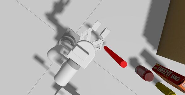
Add an RGBD Camera
Let’s add an RGBD camera to our robot so that we can eventually run a pick and place task.
Let’s start by creating a URDF file for an RGBD camera. An RGBD camera captures both color (Red Green Blue) images and depth information, allowing it to see the world in 3D like human eyes do.
Update CMakeLists.txt with the new folders we have created.
cd ~/ros2_ws/src/mycobot_ros2/mycobot_moveit_config/
Open CMakeLists.txt.
Add this code.
cmake_minimum_required(VERSION 3.8)
project(mycobot_moveit_config)

if(CMAKE_COMPILER_IS_GNUCXX OR CMAKE_CXX_COMPILER_ID MATCHES "Clang")
  add_compile_options(-Wall -Wextra -Wpedantic)
endif()

# find dependencies
find_package(ament_cmake REQUIRED)
find_package(moveit_ros_planning_interface REQUIRED)
find_package(moveit_ros_move_group REQUIRED)
find_package(moveit_kinematics REQUIRED)
find_package(moveit_planners_ompl REQUIRED)
find_package(moveit_ros_visualization REQUIRED)
find_package(rviz2 REQUIRED)
find_package(rviz_visual_tools REQUIRED)

# Copy necessary files to designated locations in the project
install (
  DIRECTORY config launch rviz
  DESTINATION share/${PROJECT_NAME}
)

# Install the .setup_assistant file
install(
  FILES .setup_assistant
  DESTINATION share/${PROJECT_NAME}
)


if(BUILD_TESTING)
  find_package(ament_lint_auto REQUIRED)
  # the following line skips the linter which checks for copyrights
  # comment the line when a copyright and license is added to all source files
  set(ament_cmake_copyright_FOUND TRUE)
  # the following line skips cpplint (only works in a git repo)
  # comment the line when this package is in a git repo and when
  # a copyright and license is added to all source files
  set(ament_cmake_cpplint_FOUND TRUE)
  ament_lint_auto_find_test_dependencies()
endif()

ament_package()
Save the file, and close it.
Create a Launch Script
Let’s bring it all together by creating a launch script.
cd ~/ros2_ws/src/mycobot_ros2/mycobot_bringup/scripts
Load and start the necessary controllers (joint_state_broadcaster, arm_controller, gripper_action_controller)
The script will then:
Start the move_group node
Launch RViz with the MoveIt configuration
Use the simulation time from Gazebo
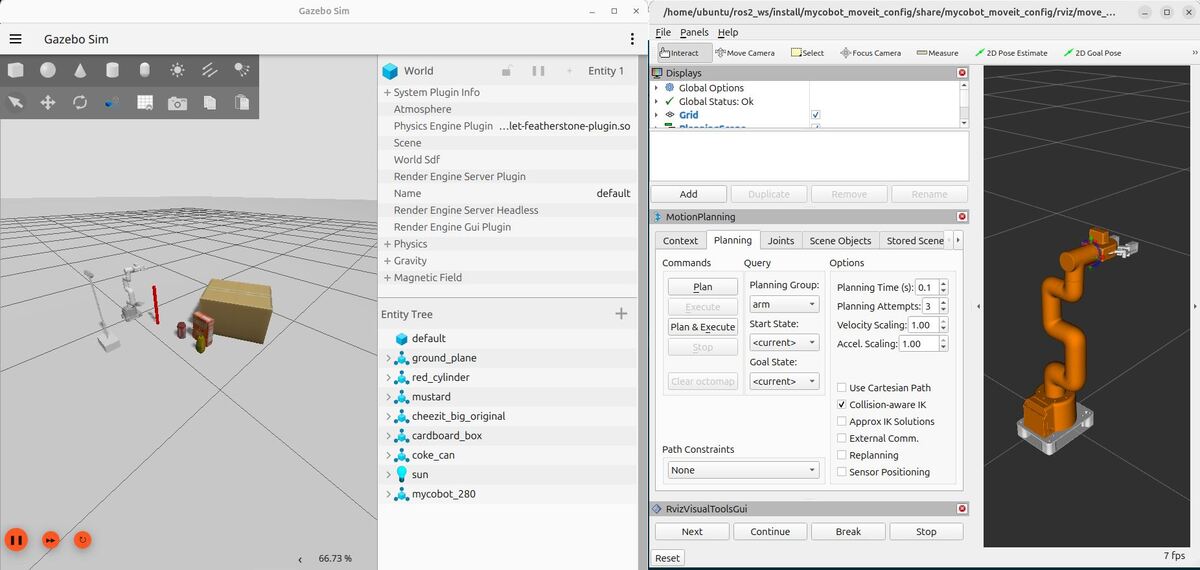
Here is what your screen should look like when everything is loaded properly. You will notice that on the right-hand side of Gazebo I closed the two panels. You can close them by right-clicking and hitting “Close”.
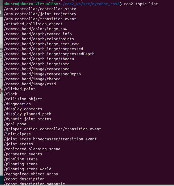
Let’s check out the active topics:
ros2 topic list
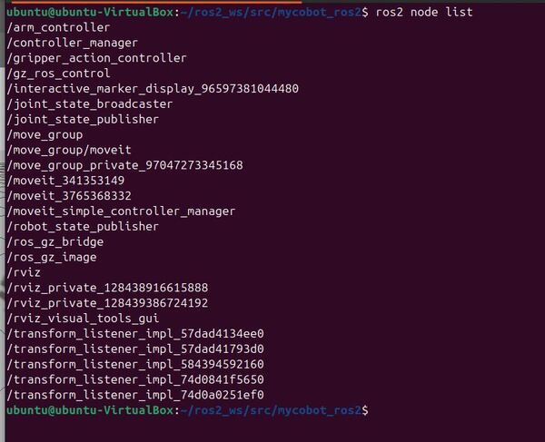
The active nodes are:
ros2 node list
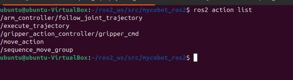
Here are our available action servers:
ros2 action list
Here are our services. You will see we have a lot of services. This page at the ROS 2 tutorials shows you how we can call services from the command line.
ros2 service list
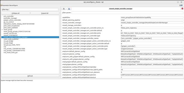
Let’s check out the parameters for the different nodes my launching a GUI tool called rqt_reconfigure:
rqt --standalone rqt_reconfigure
Click “Refresh”.
Click on any of the nodes to see the parameters for that node. For example, let’s take a look at the moveit_simple_controller_manager node.
This tool enables you to see if the parameters you set in the config file of your MoveIt package were set correctly.
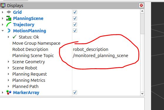
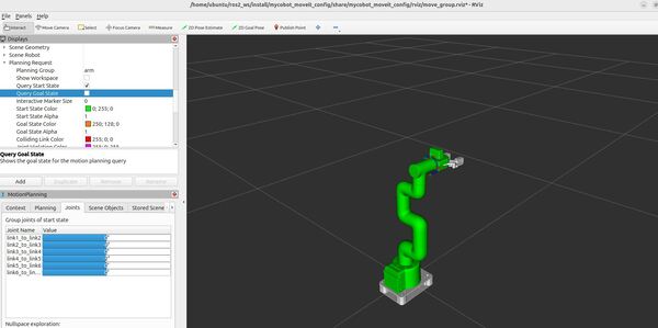
First, click on the Displays panel in the upper left.
Under Global Options, make sure the Fixed Frame is set to “base_link”
Scroll down to the MotionPlanning plugin.
Make sure the Robot Description field is set to robot_description.
Make sure the Planning Scene Topic field is set to /monitored_planning_scene.
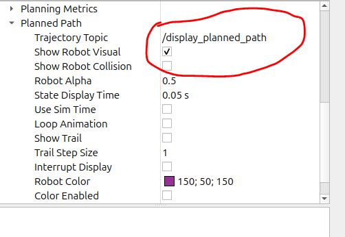
Make sure the Trajectory Topic under Planned Path is set to /display_planned_path.
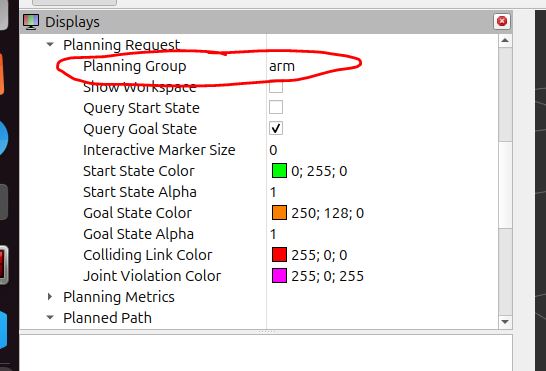
In the Planning Request section, make sure the Planning Group is set to arm. You can also see this in the MotionPlanning panel in the bottom left.
Play With the Robotic Arm
Rviz has four different visualizations for MoveIt. These visualizations are overlapping.
The robot’s configuration in the /monitored_planning_scene planning environment:
Planning Scene -> Scene Robot -> Show Robot Visual checkbox
The planned path for the robot:
Motion Planning -> Planned Path -> Show Robot Visual checkbox
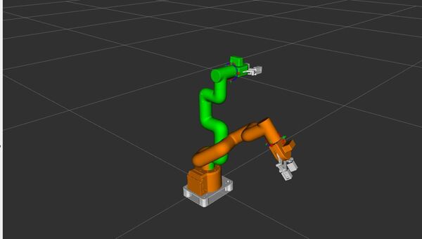
Green: The start state for motion planning:
MotionPlanning -> Planning Request -> Query Start State checkbox
Orange: The goal state for motion planning:
MotionPlanning -> Planning Request -> Query Goal State checkbox
You can toggle each of these visualizations on and off using the checkboxes in the Displays panel.
Interact With the Robotic Arm
Now let’s configure our RViz so that all we have are the scene robot, the starting state, and the goal state.
Check the Motion Planning -> Planned Path -> Show Robot Visual checkbox
Uncheck the Planning Scene -> Scene Robot -> Show Robot Visual checkbox
Uncheck the MotionPlanning -> Planning Request -> Query Start State checkbox
Check the MotionPlanning -> Planning Request -> Query Goal State checkbox
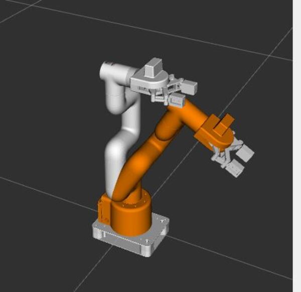
The orange colored robot represents the desired Goal State.
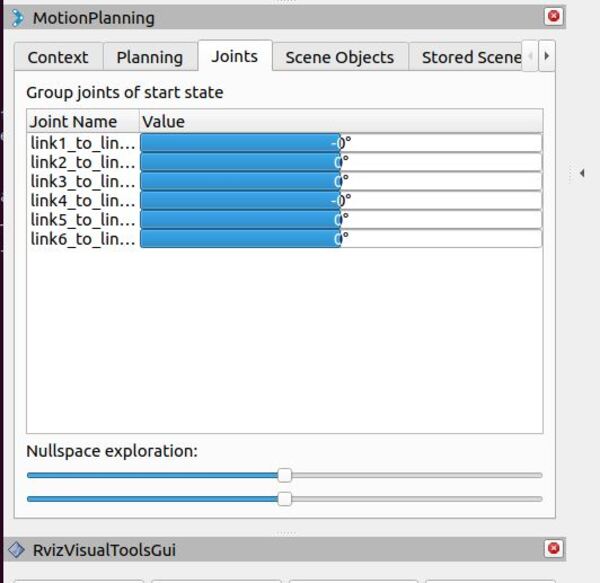
Find the “Joints” tab in the bottom MotionPlanning panel. This lets you control individual joints of the robot.
Try moving the sliders for the joints, and watch how the robot arm changes its pose.
Uncheck the MotionPlanning -> Planning Request -> Query Goal State checkbox.
Check the MotionPlanning -> Planning Request -> Query Start State checkbox.
The green colored robot is used to set the Start State for motion planning.
Use Motion Planning
Now it’s time to plan a movement for your robotic arm using RViz and MoveIt 2.
In the Displays panel in RViz, do the following…
Uncheck the MotionPlanning -> Planning Request -> Query Goal State checkbox
Check the MotionPlanning -> Planning Request -> Query Start State checkbox.
You can see if any links are in collision by going to the MotionPlanning window at the bottom and moving to the “Status” tab.
Move the green (Start State) to where you want the movement to begin.
Rather than using the interactive marker, I find it easier to go to the “Joints” tab in the Motion Planning window at the bottom. This lets you control individual joints of the robot to get your desired Start State.
Uncheck the MotionPlanning -> Planning Request -> Query Start State checkbox.
Check the MotionPlanning -> Planning Request -> Query Goal State checkbox.
Move the orange (Goal State) to where you want the movement to end.
Check the MotionPlanning -> Planning Request -> Query Start State checkbox.
Now let’s plan a motion. Look for the “MotionPlanning” window at the bottom-left part of the screen.
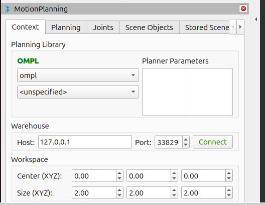
Click the Context tab.
Select ompl.
Now click the Planning tab.
Click the Plan button to generate a motion plan between the start and goal state.
The system will calculate a path, and you should see a preview of the planned motion in the 3D visualization window.
Review the planned path carefully to ensure it’s appropriate and collision-free.
If you’re not satisfied with the plan, you can adjust the start and goal states in the 3D view and plan again.
Once you’re happy with the plan, click the Plan & Execute button to make the robot carry out the planned motion.
You should see your simulated robotic arm moving in both Gazebo and RViz.
If you want to speed things up, you can tweak the Velocity Scaling figures on the Planning tab. You can make them all 1.0 for example.
Then click Plan & Execute again.
Keep setting new Goal States and moving your arm to different poses.
Be careful not to move your robot into a Goal State where the robot appears red. Red links on your robot mean the robot is colliding with itself.
If you want to open and close the gripper. The steps are the same.
Go to the MotionPlanning window at the bottom-left.
Go to the Planning tab.
Change the Planning Group to gripper.
Select closed as the Goal State. Remember this is one of the states we configured in the SRDF file.
Click Plan & Execute. No need to click Plan first and then Execute since this is a simple motion.
You should see the gripper close in Gazebo.
You can also make motion plans for the combined arm and gripper group. Have fun with it, and play around to get a feel for MoveIt2 in Rviz.
You can try other planners other than OMPL if you like.
I have set up Pilz and STOMP as some alternative motion planning libraries. Just use the dropdown menu on the Context tab.
Introspecting Trajectory Waypoints
Understanding how your robot moves in detail is important for ensuring smooth and safe operations. Let’s explore a tool that allows us to do just that:
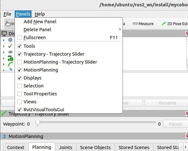
Add a new tool to RViz.
Click on the “Panels” menu
Choose “Trajectory – Trajectory Slider”
You’ll see a new slider appear in RViz
Plan a movement:
Set a new goal pose for the robotic arm.
Click the “Plan” button
Use the new Trajectory Slider:
Move the slider to see each step of the robot’s planned movement
Press the “Play” button to watch the whole movement smoothly
Remember: If you change where you want the robot to go, always click “Plan” again before using the slider or “Play” button. This makes sure you’re looking at the newest plan, not an old one.
This tool helps you understand exactly how your robot will move from start to finish.
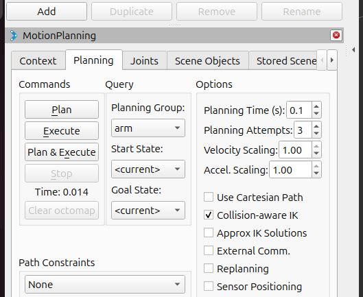
Plan Cartesian Motions
Sometimes, you want your robot to move in a straight line. Here’s how to do that.
Go to the MotionPlanning panel at the bottom-right of the screen.
Click the Planning tab.
Click the Use Cartesian Path checkbox.
What does this do?
When checked, the robot will try to move its end-effector in a straight line.
This is useful for tasks that need precise, direct movements, like drawing a straight line or moving directly towards an object.
Why is this important?
Normal planning might move the robot’s arm in a curved or complex path.
Cartesian planning ensures a more predictable, straight-line movement.
Try planning some movements with this option on and off to see the difference in how the robot moves. You will need to try different joint goal locations to get a plan that works (many will fail).
In this tutorial, we will demonstrate how to remap a topic called /chatter from the command line using ROS 2.
Remapping topics can be useful in several scenarios, such as avoiding naming conflicts when multiple nodes publish or subscribe to topics with the same name, or integrating third-party packages that use different topic names than your existing system.
We will use the built-in demo_nodes_cpp package, which contains a simple publisher (talker) and subscriber (listener) pair.
The talker node publishes messages on the /chatter topic, and the listener node subscribes to the /chatter topic.
Prerequisites
You have ROS 2 installed.
Command Line
First, open a new terminal and source your ROS 2 installation.
Run the talker node without remapping:
ros2 run demo_nodes_cpp talker
Open another terminal, and run the listener node without remapping:
ros2 run demo_nodes_cpp listener
You should see the listener node receiving messages from the talker node on the /chatter topic.
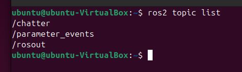
In a new terminal, run ros2 topic list to see the available topics:
ros2 topic list
You should see the /chatter topic in the list.
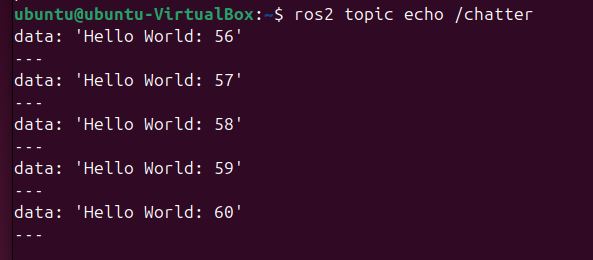
To verify that the talker node is publishing messages on the /chatter topic, run ros2 topic echo:
ros2 topic echo /chatter
You should see the messages being published by the talker node.
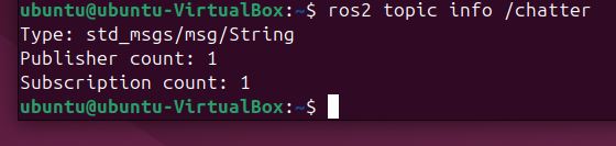
Run ros2 topic info to see the total number of publishers and subscribers for the /chatter topic:
ros2 topic info /chatter
You should see that there is one publisher and one subscriber for the /chatter topic.
Now, let’s remap the talker node to publish on a new topic called /conversation.
Stop the talker node using CTRL + C, and type this:
ros2 run demo_nodes_cpp talker --ros-args -r /chatter:=/conversation
Check the listener node terminal. You will notice that it is no longer receiving messages because it is still subscribed to the /chatter topic.
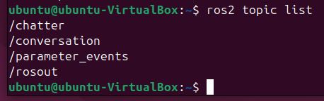
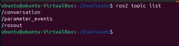
Run ros2 topic list again:
ros2 topic list
You will see the new /conversation topic in the list, but the /chatter topic is no longer present.
If you run ros2 topic echo /conversation, you will see the messages being published by the talker node on the new topic:
ros2 topic echo /conversation
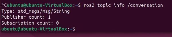
Run ros2 topic info for the /conversation topic:
ros2 topic info /conversation
You should see that there is one publisher and no subscribers for the /conversation topic.
To make the listener node receive messages from the talker node again, we need to remap its subscription from /chatter to /conversation. Stop the listener node (Ctrl+C) and run it with the remapping argument:
ros2 run demo_nodes_cpp listener --ros-args -r /chatter:=/conversation
Now, the listener node will receive messages from the talker node on the remapped /conversation topic.
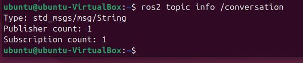
Run ros2 topic info for the /conversation topic again:
ros2 topic info /conversation
You should now see that there is one publisher and one subscriber for the /conversation topic.
In a Launch File
To remap topics using a launch file in ROS 2, you can use the <remap> tag within the <node> tag.
Create a new launch file called remap_demo.launch.py:
#!/usr/bin/env python3
"""
ROS 2 Topic Remapping Launch File.

This launch file demonstrates how to remap topics in ROS 2 by launching a talker and listener
node pair with remapped topic names. It shows how to change the default topic '/chatter'
to '/conversation' for both nodes.

Launch File Nodes:
    * talker_node (demo_nodes_cpp/talker): Publishes messages on remapped topic
    * listener_node (demo_nodes_cpp/listener): Subscribes to messages on remapped topic

Topic Remappings:
    * /chatter -> /conversation: Remaps the default topic to a new name for both nodes

Example Usage:
    $ ros2 launch your_package remap_demo.launch.py

:author: Addison Sears-Collins
:date: November 26, 2024
"""

# Import the necessary ROS 2 launch modules
from launch import LaunchDescription
from launch_ros.actions import Node


def generate_launch_description():
    """
    Generate a launch description for topic remapping demonstration.

    This function creates and returns a LaunchDescription object that specifies how
    to launch and configure the talker and listener nodes with topic remapping.

    Returns
    -------
    LaunchDescription
        A launch description object containing the configured nodes
    """
    return LaunchDescription([
        # Create and configure the talker node
        # This node will publish messages on the remapped topic '/conversation'
        Node(
            package='demo_nodes_cpp',      # The package containing the node
            executable='talker',           # The name of the executable
            name='talker_node',           # A unique name for this node instance
            remappings=[
                # Remap the default '/chatter' topic to '/conversation'
                ('/chatter', '/conversation'),
            ],
            output='screen'               # Display node output in the terminal
        ),

        # Create and configure the listener node
        # This node will subscribe to messages on the remapped topic '/conversation'
        Node(
            package='demo_nodes_cpp',      # The package containing the node
            executable='listener',         # The name of the executable
            name='listener_node',         # A unique name for this node instance
            remappings=[
                # Remap the default '/chatter' topic to '/conversation'
                # This must match the talker's remapping to receive messages
                ('/chatter', '/conversation'),
            ],
            output='screen'               # Display node output in the terminal
        ),
    ])
In this launch file, we define two nodes: talker and listener. For each node, we specify the package, executable, and name. We also use the remappings parameter to remap the /chatter topic to /conversation for both nodes.
To run the launch file, open a new terminal, source your ROS 2 installation, and navigate to the package containing the remap_demo.launch.py file. Then, run the following command:
ros2 launch remap_demo.launch.py
You should see both the talker and listener nodes running, with the talker node publishing messages on the /conversation topic and the listener node subscribing to the /conversation topic.
In a new terminal, run ros2 topic list to see the available topics:
ros2 topic list
You should see the /conversation topic in the list.
To verify that the talker node is publishing messages on the /conversation topic, run ros2 topic echo:
ros2 topic echo /conversation
You should see the messages being published by the talker node.
Run ros2 topic info for the /conversation topic:
ros2 topic info /conversation
You should see that there is one publisher and one subscriber for the /conversation topic.
Using a launch file to remap topics has several advantages:
It allows you to centralize the configuration of your nodes and their remappings in a single file.
It makes it easier to manage complex systems with multiple nodes and remappings.
It enables you to create reusable launch files that can be shared across different projects or with other users.