In this tutorial, we’ll explore the power of parameters in ROS 2. Parameters are important for creating flexible and dynamic robot software.
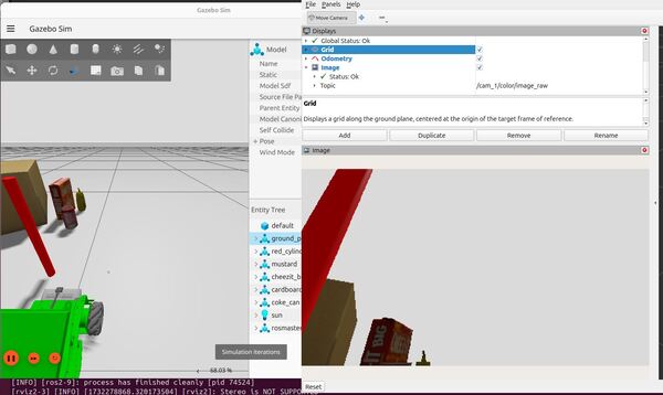
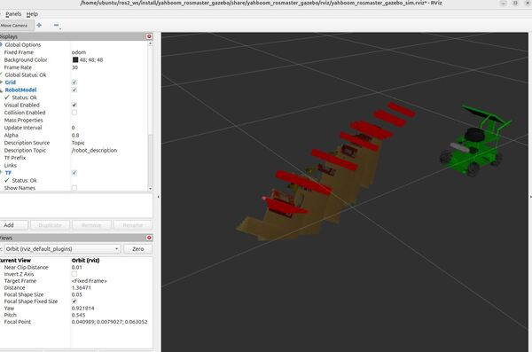
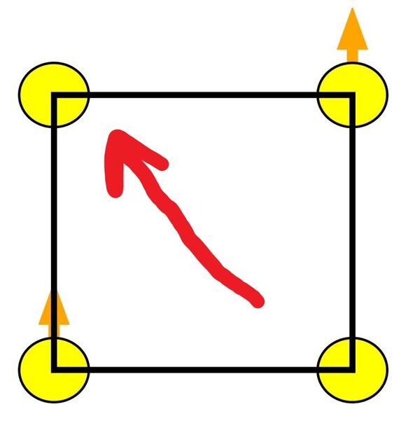
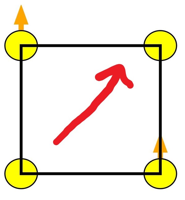
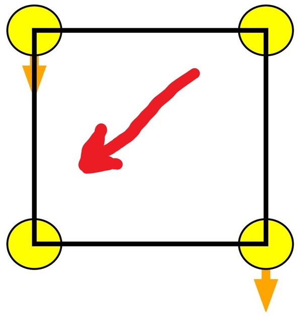
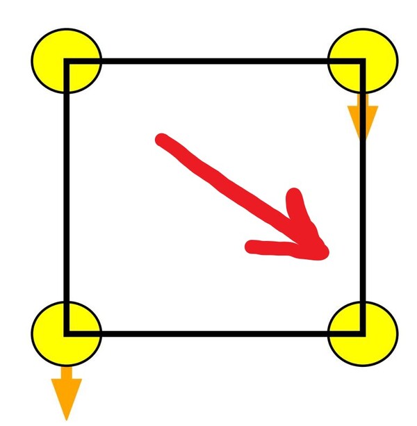
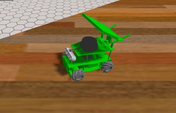
By the end of this tutorial, you will be able to use parameters to make your robot move like this:
You’ll learn how to define, access, and use parameters within your nodes, enabling you to customize your robot’s behavior without altering its code.
Join me as we dive into the essentials of parameters, setting the foundation for more complex robotics applications.
Real-World Applications
Here are some real-world examples of how ROS 2 parameters can be used in robotic applications:
- Joint Limits and Velocities: Parameters can be used to define the safe operating range (minimum and maximum) for each joint of the arm in terms of angles or positions.
- Payload Capacity: This parameter specifies the maximum weight the arm can safely carry while maintaining stability and avoiding damage to its motors or gears.
- Path Planning Parameters: These parameters influence how the arm plans its trajectory to reach a target point.
- End-effector Calibration: Parameters can store calibration data for the gripper or any tool attached to the end of the arm.
Pretty much any variable that applies to your robot can be declared as a parameter in ROS 2. Parameters are used to configure nodes at startup (and during runtime), without changing the code.
Remember, a ROS 2 node is a mini-program (written in either Python or C++) that performs a specific task within a robot system.
Prerequisites
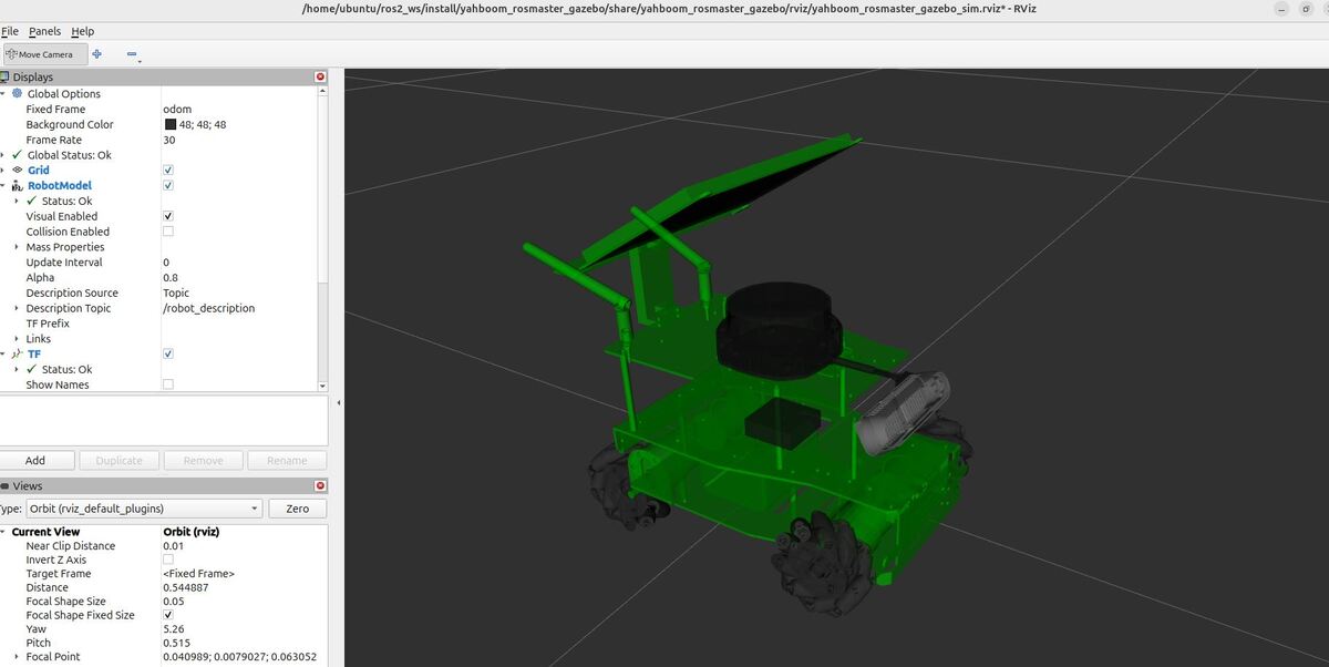
- You have completed this tutorial: How to Simulate a Mobile Robot in Gazebo – ROS 2 Jazzy
- I am assuming you are using Visual Studio Code, but you can use any code editor.
All my code for this project is located here on GitHub.
Write the Code
Let’s start by creating a ROS 2 node that declares four parameters:
- robot_name (string): Represents the name of the robot.
- robot_id (integer): The unique ID number of the robot
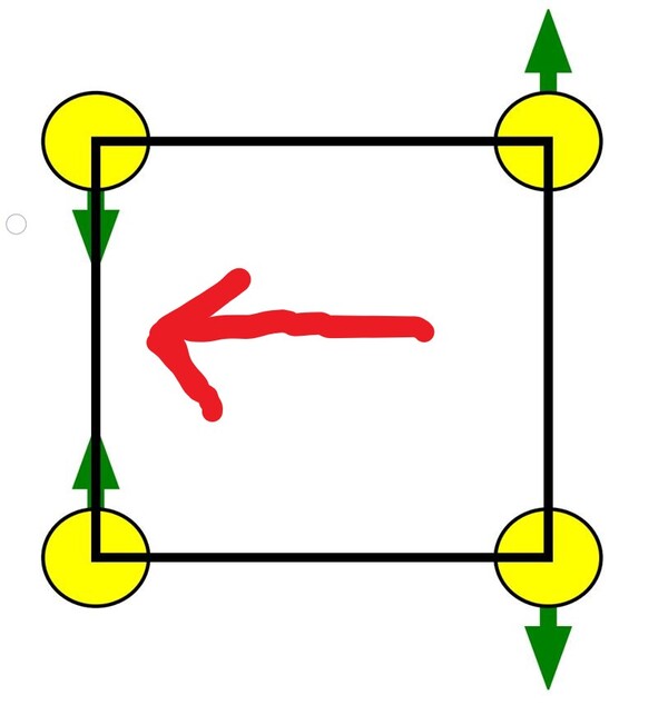
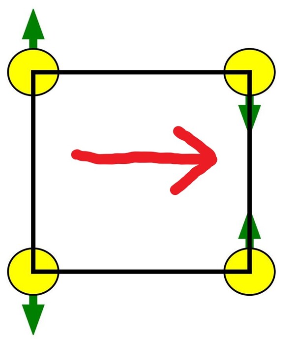
- target_linear_velocity (floating-point value): How fast we want the robot to move forward or sideways in meters per second.
- target_angular_velocity (floating-point value): How fast we want the robot to rotate in radians per second.
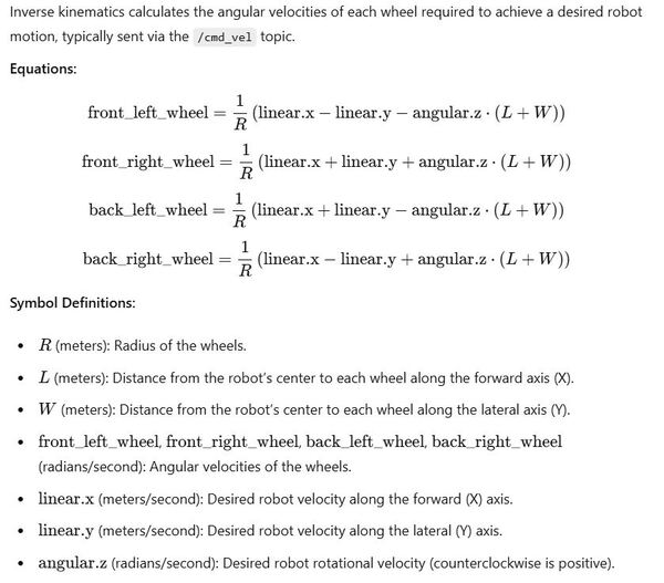
This node will include a function that executes any time one of the parameters changes. The node will also publish velocity messages (geometry_msgs/msg/TwistStamped message) to the /mecanum_drive_controller/cmd_vel topic that has as inputs the target_linear_velocity (in the x and y direction) and target_angular_velocity (rotation around the z-axis) parameters.
This publisher publishes a new velocity message at a rate of 2 Hz (two times per second), and the default velocity is 0 meters per second (for linear velocities) and 0 radians per second (for angular velocity).
Because we are parameterizing the velocity values, you can change the linear and angular velocity parameters at runtime, and the values will automatically update.
Open a new terminal window, and type:
cd ~/ros2_ws/src/yahboom_rosmaster/yahboom_rosmaster_system_tests/srcCreate a new file called mecanum_parameters_node.cpp.
Type the following code inside mecanum_parameters_node.cpp:
/**
 * @file mecanum_parameters_node.cpp
 * @brief This ROS 2 node demonstrates how to declare parameters and publish velocity messages.
 *
 * This program implements a ROS 2 node that declares parameters for a mecanum wheel robot
 * and publishes velocity commands. It demonstrates parameter declaration, callback
 * registration for parameter changes, and publishing to the velocity topic.
 *
 * Subscription Topics:
 *   None
 *
 * Publishing Topics:
 *   /mecanum_drive_controller/cmd_vel (geometry_msgs/TwistStamped): Velocity command for the robot
 *   (linear.x, linear.y, and angular.z)
 *
 * Parameters:
 *   robot_name (string): The name of the robot
 *   robot_id (int): The unique ID number of the robot
 *   target_linear_velocity_x (double): Target linear velocity in x direction (m/s)
 *   target_linear_velocity_y (double): Target linear velocity in y direction (m/s)
 *   target_angular_velocity (double): Target angular velocity in radians per second
 *
 * @author Addison Sears-Collins
 * @date November 24, 2024
 */

#include <rclcpp/rclcpp.hpp>
#include <rcl_interfaces/msg/parameter_descriptor.hpp>
#include <rcl_interfaces/msg/set_parameters_result.hpp>
#include <geometry_msgs/msg/twist_stamped.hpp>

/**
 * @class MecanumParameters
 * @brief A ROS 2 node that demonstrates parameter handling and velocity publishing.
 */
class MecanumParameters : public rclcpp::Node
{
public:
  /**
   * @brief Constructor for the MecanumParameters node.
   *
   * Initializes the node, declares parameters, sets up parameter change callback,
   * and creates a publisher and timer for velocity messages.
   */
  MecanumParameters() : Node("mecanum_parameters_node")
  {
    // Describe parameters
    rcl_interfaces::msg::ParameterDescriptor robot_name_descriptor;
    robot_name_descriptor.description = "The name of the robot";
    rcl_interfaces::msg::ParameterDescriptor robot_id_descriptor;
    robot_id_descriptor.description = "The unique ID number of the robot";
    rcl_interfaces::msg::ParameterDescriptor target_linear_velocity_x_descriptor;
    target_linear_velocity_x_descriptor.description = "Target linear velocity in x direction (meters per second)";
    rcl_interfaces::msg::ParameterDescriptor target_linear_velocity_y_descriptor;
    target_linear_velocity_y_descriptor.description = "Target linear velocity in y direction (meters per second)";
    rcl_interfaces::msg::ParameterDescriptor target_angular_velocity_descriptor;
    target_angular_velocity_descriptor.description = "Target angular velocity in radians per second";

    // Declare parameters using declare_parameter()
    this->declare_parameter("robot_name", "Automatic Addison Bot", robot_name_descriptor);
    this->declare_parameter("robot_id", 1, robot_id_descriptor);
    this->declare_parameter("target_linear_velocity_x", 0.0, target_linear_velocity_x_descriptor);
    this->declare_parameter("target_linear_velocity_y", 0.0, target_linear_velocity_y_descriptor);
    this->declare_parameter("target_angular_velocity", 0.0, target_angular_velocity_descriptor);

    // Register a callback function for parameter changes using the newer method
    param_callback_handle_ = this->add_on_set_parameters_callback(
      std::bind(&MecanumParameters::parameter_change_callback, this, std::placeholders::_1));

    // Create a publisher for the /mecanum_drive_controller/cmd_vel topic
    velocity_publisher_ = this->create_publisher<geometry_msgs::msg::TwistStamped>("/mecanum_drive_controller/cmd_vel", 10);

    // Create a timer that will call the publish_velocity function every 0.5 seconds (2 Hz)
    timer_ = this->create_wall_timer(std::chrono::milliseconds(500), std::bind(&MecanumParameters::publish_velocity, this));
  }

private:
  /**
   * @brief Callback function for parameter changes.
   *
   * @param params A vector of rclcpp::Parameter objects representing the parameters that are
   *               being attempted to change.
   * @return rcl_interfaces::msg::SetParametersResult Object indicating whether the change was successful.
   */
  rcl_interfaces::msg::SetParametersResult parameter_change_callback(const std::vector<rclcpp::Parameter> & params)
  {
    rcl_interfaces::msg::SetParametersResult result;
    result.successful = true;

    for (const auto & param : params)
    {
      if (param.get_name() == "robot_name" && param.get_type() == rclcpp::ParameterType::PARAMETER_STRING)
      {
        RCLCPP_INFO(this->get_logger(), "Parameter robot_name has changed. The new value is: %s", param.as_string().c_str());
      }
      else if (param.get_name() == "robot_id" && param.get_type() == rclcpp::ParameterType::PARAMETER_INTEGER)
      {
        RCLCPP_INFO(this->get_logger(), "Parameter robot_id has changed. The new value is: %ld", param.as_int());  // Changed %d to %ld
      }
      else if (param.get_name() == "target_linear_velocity_x" && param.get_type() == rclcpp::ParameterType::PARAMETER_DOUBLE)
      {
        RCLCPP_INFO(this->get_logger(), "Parameter target_linear_velocity_x has changed. The new value is: %f", param.as_double());
      }
      else if (param.get_name() == "target_linear_velocity_y" && param.get_type() == rclcpp::ParameterType::PARAMETER_DOUBLE)
      {
        RCLCPP_INFO(this->get_logger(), "Parameter target_linear_velocity_y has changed. The new value is: %f", param.as_double());
      }
      else if (param.get_name() == "target_angular_velocity" && param.get_type() == rclcpp::ParameterType::PARAMETER_DOUBLE)
      {
        RCLCPP_INFO(this->get_logger(), "Parameter target_angular_velocity has changed. The new value is: %f", param.as_double());
      }
      else
      {
        result.successful = false;
        result.reason = "Unknown parameter: " + param.get_name();
        break;
      }
    }
    return result;
  }

  /**
   * @brief Publishes velocity messages to the /mecanum_drive_controller/cmd_vel topic.
   *
   * This function is called periodically by the timer to publish the current
   * target linear and angular velocities.
   */
  void publish_velocity()
  {
    double target_linear_velocity_x = this->get_parameter("target_linear_velocity_x").as_double();
    double target_linear_velocity_y = this->get_parameter("target_linear_velocity_y").as_double();
    double target_angular_velocity = this->get_parameter("target_angular_velocity").as_double();

    geometry_msgs::msg::TwistStamped velocity_msg;
    velocity_msg.header.stamp = this->get_clock()->now();
    velocity_msg.header.frame_id = "base_link";
    velocity_msg.twist.linear.x = target_linear_velocity_x;
    velocity_msg.twist.linear.y = target_linear_velocity_y;
    velocity_msg.twist.angular.z = target_angular_velocity;

    velocity_publisher_->publish(velocity_msg);
  }

  rclcpp::Publisher<geometry_msgs::msg::TwistStamped>::SharedPtr velocity_publisher_;  ///< Publisher for velocity commands
  rclcpp::TimerBase::SharedPtr timer_;  ///< Timer for periodic velocity publishing
  OnSetParametersCallbackHandle::SharedPtr param_callback_handle_;  ///< Handle for the parameter callback
};

/**
 * @brief Main function to start the ROS 2 node.
 *
 * Initializes ROS 2, creates an instance of the MecanumParameters node,
 * and keeps it running to process callbacks and publish messages.
 *
 * @param argc Number of command-line arguments.
 * @param argv Array of command-line argument strings.
 * @return int Return code (0 for normal exit).
 */
int main(int argc, char ** argv)
{
  rclcpp::init(argc, argv);
  auto mecanum_parameters_node = std::make_shared<MecanumParameters>();
  rclcpp::spin(mecanum_parameters_node);
  rclcpp::shutdown();
  return 0;
}
Save the file, and close it.
Edit package.xml
Now let’s modify our package.xml file to update the package dependencies. Either open the package.xml file if you are using VS Code, or type this:
cd ~/ros2_ws/src/yahboom_rosmaster/yahboom_rosmaster_system_tests/gedit package.xmlAdd this line in the dependencies section:
<depend>rcl_interfaces</depend>
Save the file, and close it.
Update CMakeLists.txt
Now we need to edit the CMakeLists.txt file.
Open CMakeLists.txt, and make sure it looks like this:
Be sure to add the mecanum_parameters_node.cpp program.
cmake_minimum_required(VERSION 3.8)
project(yahboom_rosmaster_system_tests)

if(CMAKE_COMPILER_IS_GNUCXX OR CMAKE_CXX_COMPILER_ID MATCHES "Clang")
  add_compile_options(-Wall -Wextra -Wpedantic)
endif()

# find dependencies
find_package(ament_cmake REQUIRED)
find_package(rclcpp REQUIRED)
find_package(geometry_msgs REQUIRED)
find_package(std_msgs REQUIRED)
find_package(rcl_interfaces REQUIRED)

# Copy necessary files to designated locations in the project
install (
  DIRECTORY config launch
  DESTINATION share/${PROJECT_NAME}
)

# Add the square mecanum controller executable
add_executable(square_mecanum_controller
  src/square_mecanum_controller.cpp
)

# Add the mecanum parameters node executable
add_executable(mecanum_parameters_node
  src/mecanum_parameters_node.cpp
)

# Specify dependencies for the target
ament_target_dependencies(square_mecanum_controller
  rclcpp
  geometry_msgs
  std_msgs
)

# Specify dependencies for the mecanum parameters node
ament_target_dependencies(mecanum_parameters_node
  rclcpp
  geometry_msgs
  std_msgs
  rcl_interfaces
)

# Install the executables
install(TARGETS
  square_mecanum_controller
  mecanum_parameters_node
  DESTINATION lib/${PROJECT_NAME}
)

if(BUILD_TESTING)
  find_package(ament_lint_auto REQUIRED)
  # the following line skips the linter which checks for copyrights
  # comment the line when a copyright and license is added to all source files
  set(ament_cmake_copyright_FOUND TRUE)
  # the following line skips cpplint (only works in a git repo)
  # comment the line when this package is in a git repo and when
  # a copyright and license is added to all source files
  set(ament_cmake_cpplint_FOUND TRUE)
  ament_lint_auto_find_test_dependencies()
endif()

ament_package()
Save the file, and close it.
Build the Workspace
Open a terminal window, and type:
cd ~/ros2_ws/colcon build && source ~/.bashrcOr you can type my alias:
buildLaunch the Robot
Now let’s launch the mobile robot.
Open a terminal window, and type the following command:
x3 or
bash ~/ros2_ws/src/yahboom_rosmaster/yahboom_rosmaster_bringup/scripts/rosmaster_x3_gazebo.shRun the node you created earlier. Open a new terminal and type:
ros2 run yahboom_rosmaster_system_tests mecanum_parameters_nodeNow, press Enter.
Open a new terminal window.
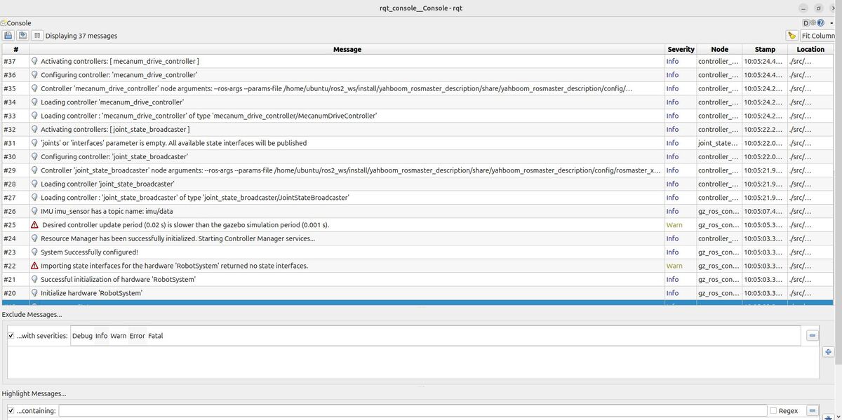
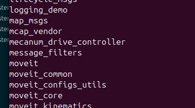
What are the currently active nodes?
ros2 node list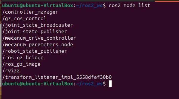
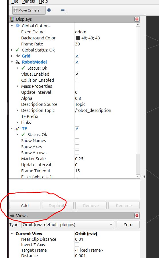
List all the parameters for all nodes in the ROS2 system.
ros2 param listRetrieve the value of a specific parameter for a node.
ros2 param get /mecanum_parameters_node robot_nameString value is: Automatic Addison Bot
ros2 param get /mecanum_parameters_node robot_idInteger value is: 1
ros2 param get /mecanum_parameters_node target_linear_velocity_xDouble value is: 0.0
ros2 param get /mecanum_parameters_node target_linear_velocity_yDouble value is: 0.0
ros2 param get /mecanum_parameters_node target_angular_velocityDouble value is: 0.0
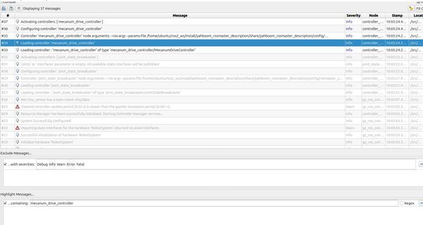
Let’s change the name of the robot:
ros2 param set /mecanum_parameters_node robot_name "New Automatic Addison Bot"Set parameter successful
Double check the new value:
ros2 param get /mecanum_parameters_node robot_nameString value is: New Automatic Addison Bot
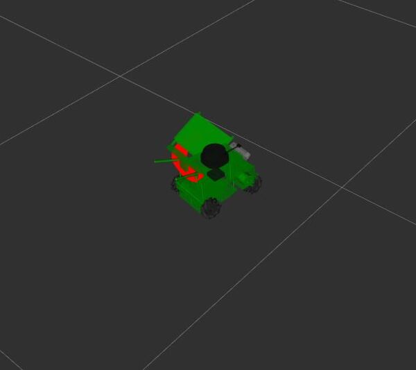
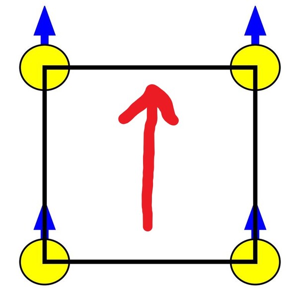
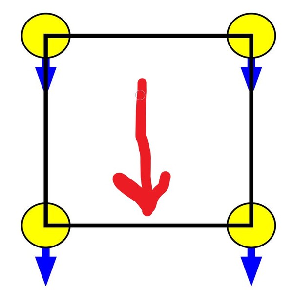
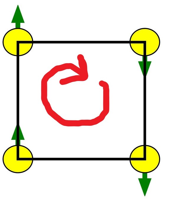
Let’s make the robot rotate clockwise:
ros2 param set /mecanum_parameters_node target_angular_velocity -0.5ros2 param get /mecanum_parameters_node target_angular_velocityDouble value is: -0.5
Now go back to the terminals where your scripts are running and press CTRL + C to stop the execution.
To clear the terminal window, type:
clearCreate Your Own YAML File to Set Parameters in a Launch File
Now we will create a YAML file containing our desired parameters. We will then import that YAML file into a launch file and launch the robot in Gazebo.
Create the Launch File
Go to this folder:
cd ~/ros2_ws/src/yahboom_rosmaster/yahboom_rosmaster_system_tests/mkdir launchcd launchCreate a new file called mecanum_parameters.launch.py.
Open a new terminal window, and type the following code:
#!/usr/bin/env python3
"""
Launch file for mecanum_parameters_node.

This launch file launches the mecanum_parameters_node with configurable parameters.

:author: Addison Sears-Collins
:date: November 24, 2024
"""

import os
from launch import LaunchDescription
from launch.actions import DeclareLaunchArgument
from launch.substitutions import LaunchConfiguration
from launch_ros.actions import Node
from launch_ros.substitutions import FindPackageShare


def generate_launch_description():
    """
    Generate a launch description for the mecanum_parameters_node.

    :return: A LaunchDescription object containing the actions to execute.
    :rtype: LaunchDescription
    """

    # Constants for paths to different files and folders
    package_name_system_tests = 'yahboom_rosmaster_system_tests'

    mecanum_params_path = 'config/mecanum_parameters.yaml'

    # Set the path to different files and folders
    pkg_share_system_tests = FindPackageShare(
        package=package_name_system_tests).find(package_name_system_tests)

    mecanum_params_path = os.path.join(pkg_share_system_tests, mecanum_params_path)

    # Launch configuration variables
    mecanum_params = LaunchConfiguration('mecanum_params')

    # Declare the launch arguments
    declare_mecanum_params_cmd = DeclareLaunchArgument(
        name='mecanum_params',
        default_value=mecanum_params_path,
        description='Full path to parameters for the parameters file.')

    # Launch the mecanum_parameters_node
    start_mecanum_parameters_node_cmd = Node(
        package=package_name_system_tests,
        executable='mecanum_parameters_node',
        parameters=[mecanum_params],
        output='screen')

    # Create the launch description and populate it
    ld = LaunchDescription()

    # Declare the launch options
    ld.add_action(declare_mecanum_params_cmd)

    # Add actions to the launch description
    ld.add_action(start_mecanum_parameters_node_cmd)

    return ld
Save the file, and close it.
Create the YAML File
Now let’s create the configuration file.
cd ~/ros2_ws/src/yahboom_rosmaster/yahboom_rosmaster_system_tests/mkdir configcd configCreate a new file called mecanum_parameters.yaml.
# Desired parameter values
/mecanum_parameters_node:
ros__parameters:
robot_name: "New Automatic Addison Bot"
robot_id: 82
target_linear_velocity_x: 0.0
target_linear_velocity_y: 0.0
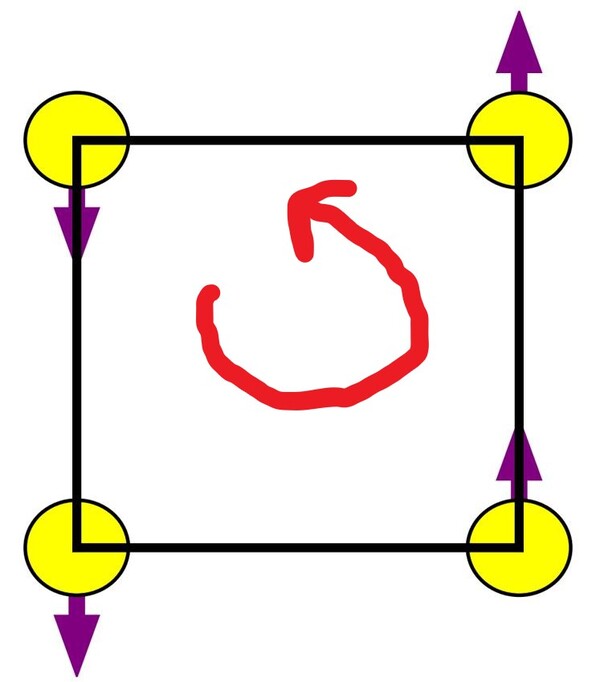
target_angular_velocity: 0.23
Save the file, and close it.
Update CMakeLists.txt
Update your CMakeLists.txt with the new launch and config folders.
# Copy necessary files to designated locations in the project
install (
  DIRECTORY config launch
  DESTINATION share/${PROJECT_NAME}
)
Build the Workspace
Open a terminal window, and type:
build(Note this “build” is my alias for “cd ~/ros2_ws/ && colcon build && source ~/.bashrc)
Launch the Robot Again
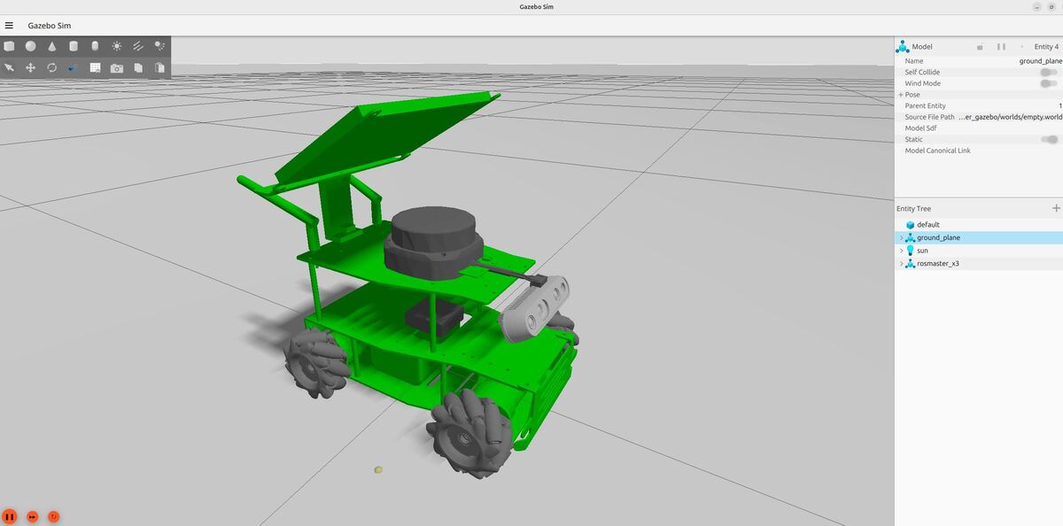
To launch the robot with the default parameter values, you can do this:
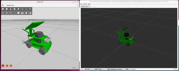
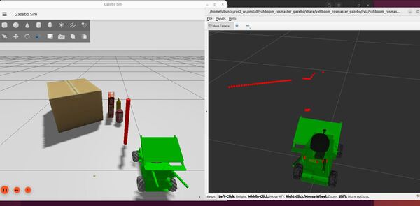
x3In another terminal window, type:
ros2 launch yahboom_rosmaster_system_tests mecanum_parameters.launch.pyThe robot should start to rotate counter-clockwise.
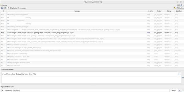
Let’s check the velocity values:
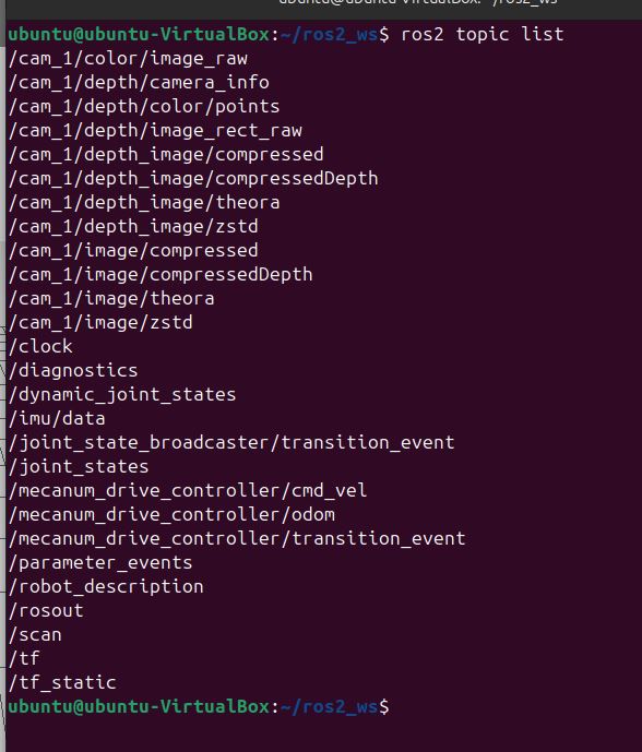
ros2 topic echo /mecanum_drive_controller/cmd_vel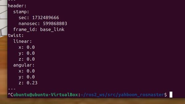
Press CTRL + C to stop the robot.
That’s it! Keep building!