In this tutorial, we will get started with Python development for robotics projects.
Prerequisites
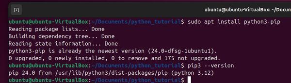
- You have completed this tutorial: How to Install Python in Ubuntu Linux – ROS 2
ROS 2 Python Style Guide
Before we get started, it is important to note that we will be following the ROS 2 Python Style Guide throughout this tutorial and future tutorials where we use Python. This guide is based on PEP 8, the official style guide for Python code, with some ROS 2-specific modifications.
- 4 spaces for indents
- 100 characters max per line
- Single quotes for strings
- Imports at the top, grouped by type
- snake_case for functions and variables
- CapWords convention for class names
Adhering to these guidelines will help make sure your code is consistent with ROS 2 projects in the community that use Python.
Create a Folder to Store Your Python Code
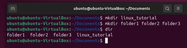
Let’s start by creating a folder to store our Python code. Open a terminal window, and type:
mkdir -p ~/Documents/python_tutorialcd ~/Documents/python_tutorialOpen Visual Studio Code (Optional)
For those of you who will be using Visual Studio Code for your Python development, type this:
code .Otherwise, you can open your favorite code editor.
Configure Visual Studio Code (Optional)
Let’s configure our settings so that our code follows the ROS 2 Python Style Guide which uses the PEP8 standards.
Click on the Extensions button on the left side.
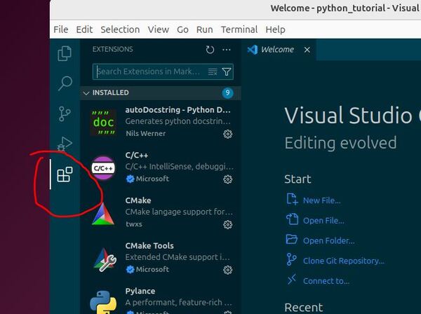
Type autopep8 in the search bar.
Click Install the version made by Microsoft.
Type PyLint in the search bar.
Click Install the version made by Microsoft.
Click on “File” in the top-left corner.
Select “Preferences”
Click on “Settings”.
In the search bar at the top of the Settings page, type “editor rulers” and click “Edit in settings.json”.
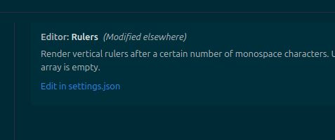
Add or modify:
{
 "workbench.colorTheme": "Solarized Dark",
 "editor.fontSize": 30,
 "terminal.integrated.fontSize": 30,
 "editor.rulers": [100],
 "[python]": {
   "editor.formatOnSave": true,
   "editor.defaultFormatter": "ms-python.autopep8",
   "editor.tabSize": 4,
   "editor.insertSpaces": true
 },
 "[cpp]": {
   "editor.tabSize": 2,
   "editor.insertSpaces": true
 },
 "editor.tabSize": 2,
 "editor.insertSpaces": true,
 "files.trimTrailingWhitespace": true,
 "autopep8.args": [
   "--max-line-length",
   "100",
   "--aggressive"
 ]
}
Save and close the settings.json file.
Let’s create a new Python file with intentional style issues to test our PEP 8 compliance setup.
To test the configuration, create a new Python file named test_formatting.py. Right-click underneath the name of the folder on the left panel: “PYTHON_TUTORIAL”.
Click “New File”.
Name the file test_formatting.py.
Press Enter.
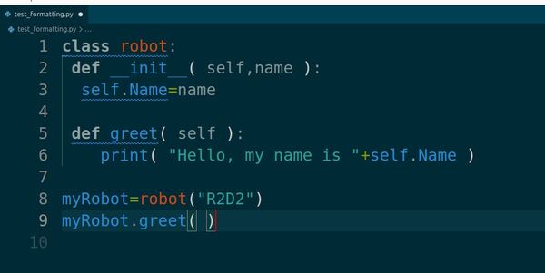
Paste the following code with intentional style issues:
class robot:
 def __init__( self,name ):
  self.Name=name

 def greet( self ):
    print( "Hello, my name is "+self.Name )

myRobot=robot("R2D2")
myRobot.greet( )
Save the file. You should immediately see some changes and warnings. Let’s examine what autopep8 has automatically fixed and what issues remain.
After saving, your code should look more like this:
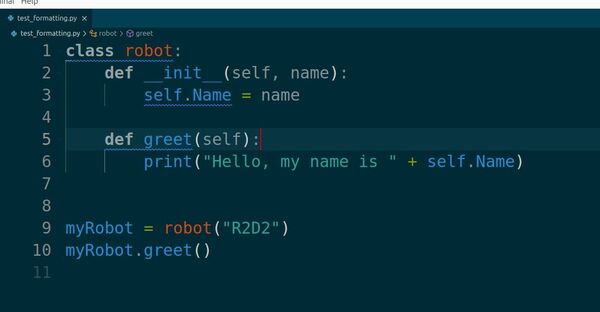
class robot:
    def __init__(self, name):
        self.Name = name

    def greet(self):
        print("Hello, my name is " + self.Name)


myRobot = robot("R2D2")
myRobot.greet()
autopep8 has automatically fixed several issues:
- Corrected indentation to use 4 spaces
- Fixed spacing around operators and after commas
- Removed extra spaces inside parentheses
However, there are still style problems that autopep8 doesn’t address. These should be highlighted by PyLint:
- Class name should be in CapWords format (PascalCase)
- Variable names should be in snake_case
- The file, class, and methods need to have docstrings, which provide an explanation of what the code does (docstrings can be added directly in VS Code by going on the line underneath the method or class, and typing “””.
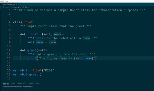
To fix these remaining issues, manually update your code as follows:
"""This module defines a simple Robot class for demonstration purposes."""


class Robot:
    """Simple robot class that can greet."""

    def __init__(self, name):
        """Initialize the robot with a name."""
        self.name = name

    def greet(self):
        """Print a greeting from the robot."""
        print(f"Hello, my name is {self.name}")


my_robot = Robot("R2D2")
my_robot.greet()
After making these changes and saving the file, you should see no more warnings in the “Problems” tab at the bottom of your screen.
By using autopep8 and PyLint in VS Code, we’ve set up an environment that helps us adhere to the ROS 2 Python Style Guide. autopep8 automatically handles many formatting issues, while PyLint provides additional guidance on style and best practices.
Remember, while these tools are extremely helpful, they don’t catch everything. It’s important to understand the principles behind the style guide and apply them as you write your code.
In future robotics projects, this setup will help you write clean, consistent Python code that adheres to ROS 2 standards, making your code more readable and maintainable.
Finally, let’s run the code.
Look for the “Run” button (a triangle play icon) in the top-right corner of the editor.
Click this button to run the currently open Python file.
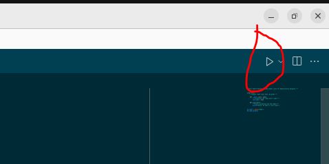
You should get this output:
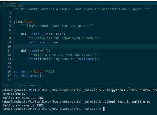
Hello, my name is R2D2
You can also run the file, by going to the terminal window, and typing:
python3 test_formatting.pyCreating Variables
In this section, we will learn how to create and use variables in Python.
Variables in Python are like containers; they store data values. Unlike some other programming languages, Python has no command for declaring a variable. A variable is created the moment you first assign a value to it.
Let’s begin. Right-click in the Explorer pane and select “New File”.
Name the file robot_variables.py, and press Enter.
In the new file, let’s start by creating our first variable:
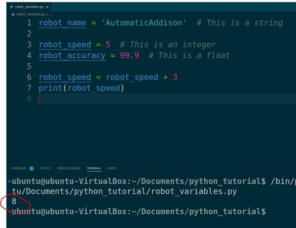
robot_name = 'AutomaticAddison'
Here, robot_name is a variable, and we’ve assigned it the value ‘AutomaticAddison’, which is a string.
Python knows the type of the variable based on the value it’s given. This feature is known as dynamic typing.
You can also store numbers in variables. Let’s create an integer variable and a floating-point variable:
robot_speed = 5  # This is an integer
robot_accuracy = 99.9  # This is a float
The # symbol in Python is used to create comments. Comments are notes within the code that Python ignores when running the program.
We can use variables to perform calculations.
For example, if we want to increase the robot_speed by 3, we can do so like this:
robot_speed = robot_speed + 3
print(robot_speed)
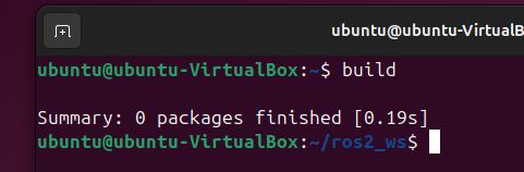
Now run the code.
In the terminal, you’ll see the value of robot_speed printed out.
Notice how we used the same variable to update its own value.
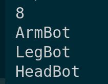
Python also allows you to create multiple variables in a single line. Here’s how you can assign different robot parts to different variables simultaneously:
arm, leg, head = 'ArmBot', 'LegBot', 'HeadBot'
print(arm)
print(leg)
print(head)
Run the code.
Finally, variables can be reassigned to different data types.
For example, if we want to reassign robot_speed to a string, we can do that like this:
robot_speed = 'fast'
print(robot_speed)
Run the code again.
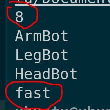
And just like that, robot_speed now holds a string instead of an integer.
Understanding Data Types
Let’s learn about data types in Python.
In Python, data types are the classifications we give to different kinds of data. Understanding them helps you manage how Python will process your data.
Let’s look at the most common data types used in Python.
In VS Code, right-click in the Explorer pane and select “New File”.
Name the file robot_data_types.py and press Enter.
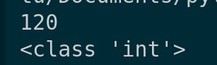
First, we have integers, known as int. These are whole numbers without a decimal point. For example:
distance = 120
print(distance)

#Check the data type
print(type(distance))
Here is the output:
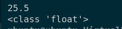
Next is the floating-point number, or float, which is a number with a decimal. It’s often used in Python for more precise measurements or calculations:
speed = 25.5
print(speed)

#Check the data type
print(type(speed))
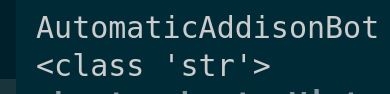
Strings, or str, are sequences of characters used for storing text. In Python, you enclose strings in quotes:
robot_name = 'AutomaticAddisonBot'
print(robot_name)

# Check the data type
print(type(robot_name))
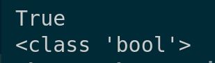
Booleans, or bool, represent one of two values: True or False. This data type is useful when dealing with conditions in your programming:
is_active = True
print(is_active)

# Check the data type
print(type(is_active))
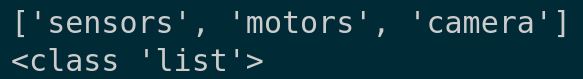
Lists are ordered collections of values that can hold a mix of data types, and they are mutable, meaning you can change their content without changing their identity:
components = ['sensors', 'motors', 'camera']
print(components)

# Check the data type
print(type(components))
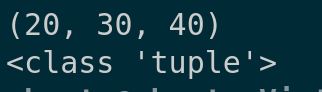
Tuples are similar to lists, but they are immutable, meaning once they are created, their values cannot be changed:
dimensions = (20, 30, 40)
print(dimensions)

# Check the data type
print(type(dimensions))
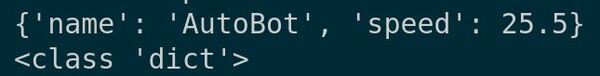
Dictionaries, or dict, store key-value pairs and are extremely useful for storing data items like a database:
robot_specs = {'name': 'AutoBot', 'speed': 25.5}
print(robot_specs)

# Check the data type
print(type(robot_specs))
Understanding Casting
Let’s explore the concept of casting in Python.
Casting is important when you need to specify or alter the data type of a variable in your code. This is particularly useful in robotics when you need to ensure that data types match expected parameters for functions or calculations.
In VS Code, right-click in the Explorer pane and select “New File”.
Name the file robot_casting.py and press Enter.
First, if you have a number as a string but need to perform mathematical operations, you’ll need to convert it to an integer or float:
speed_str = '30'
print(speed_str)
print(type(speed_str))

speed_int = int(speed_str)
print(speed_int)
print(type(speed_int))
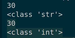
This converts the string ’30’ to the integer 30, enabling arithmetic operations.
Similarly, if you’re working with floating-point numbers but need to convert them to integers for functions that do not accept floats, you can use:
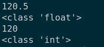
distance_float = 120.5
print(distance_float)
print(type(distance_float))

distance_int = int(distance_float)
print(distance_int)
print(type(distance_int))
Here, distance_float is converted to 120, truncating the decimal part.
On the other hand, sometimes you need to perform accurate division calculations with integers. In Python, dividing two integers yields an integer result.
To get a float result, one of the numbers must be a float. You can achieve this by casting:
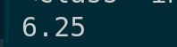
length = 25
width = 4
aspect_ratio = float(length) / width

print(aspect_ratio)
This ensures aspect_ratio holds the value 6.25 rather than just 6.
Lastly, let’s look at converting numbers to strings, which is common when you need to concatenate numbers to strings for messages or outputs:
age = 5
age_str = str(age)
message = 'The robot is ' + age_str + ' years old.'
print(message)
This casts the integer 5 to the string ‘5’, making it possible to construct the full message string without errors.

Working with Output
Let’s see how to work with output in Python. Managing output effectively is important for debugging, monitoring the state of your robotics applications, and providing interactive user experiences. Let’s get started.
In VS Code, right-click in the Explorer pane and select “New File”.
Name the file robot_output.py and press Enter.
In Python, the print() function is the most common way to output data. Whether you’re outputting simple messages or complex data structures, print() can handle it all. Let’s look at some examples.
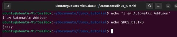
First, a straightforward message:
print("Hello, robot world!")
This sends the text “Hello, robot world!” to the console, which is useful for simple notifications about the program’s status.
You can also use the print() function to output multiple items in one line by separating them with commas:
robot_name = 'AutomaticAddisonBot'
task_status = 'active'

print('Robot Name:', robot_name, '- Status:', task_status)
This will output:

For more complex outputs, you might want to format strings. Python’s string formatting capabilities are powerful.
Here’s how you can use formatted string literals, also known as f-strings:
battery_level = 85
print(f'Battery Level: {battery_level}%')
This injects the value of battery_level directly into the string, making it simpler to construct detailed messages dynamically.
Sometimes, you may want to redirect your output from the console to a file. This is especially useful for logging data that you want to review later. Here’s how you can do it:
with open('log.txt', 'a') as file:
    print('An error occurred', file=file)
This code snippet opens log.txt in append mode (‘a’) and writes “An error occurred” to the file instead of the console.
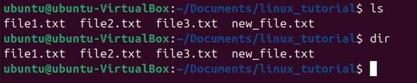
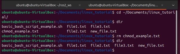
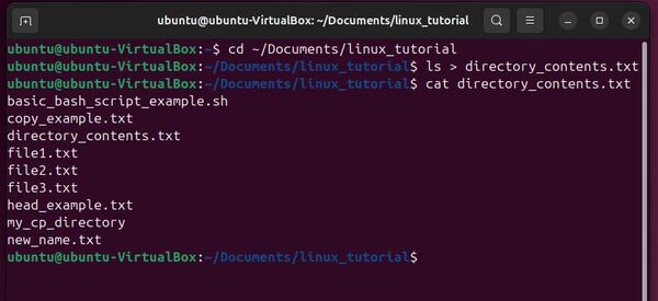
In the terminal window, type:
dirYou will see our new file log.txt.
That’s it for this tutorial! You’ve taken your first big step into Python programming. Thanks for following along with me, and I will see you in the next tutorial.
Keep building!