In this tutorial, we will demonstrate how to remap a topic called /chatter from the command line using ROS 2.
Remapping topics can be useful in several scenarios, such as avoiding naming conflicts when multiple nodes publish or subscribe to topics with the same name, or integrating third-party packages that use different topic names than your existing system.
We will use the built-in demo_nodes_cpp package, which contains a simple publisher (talker) and subscriber (listener) pair.
The talker node publishes messages on the /chatter topic, and the listener node subscribes to the /chatter topic.
Prerequisites
- You have ROS 2 installed.
Command Line
First, open a new terminal and source your ROS 2 installation.
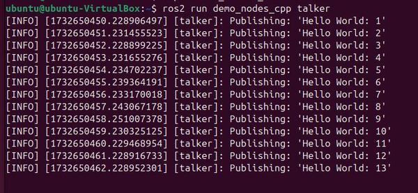
Run the talker node without remapping:
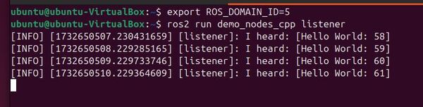
ros2 run demo_nodes_cpp talkerOpen another terminal, and run the listener node without remapping:
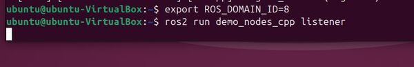
ros2 run demo_nodes_cpp listenerYou should see the listener node receiving messages from the talker node on the /chatter topic.
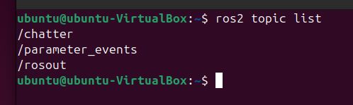
In a new terminal, run ros2 topic list to see the available topics:
ros2 topic listYou should see the /chatter topic in the list.
To verify that the talker node is publishing messages on the /chatter topic, run ros2 topic echo:
ros2 topic echo /chatter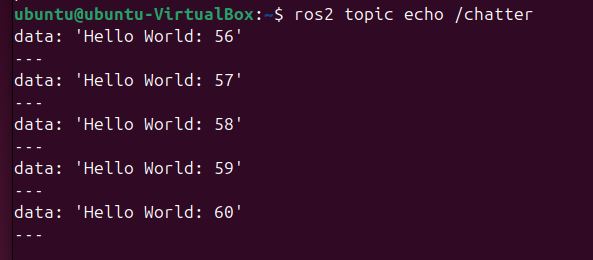
You should see the messages being published by the talker node.
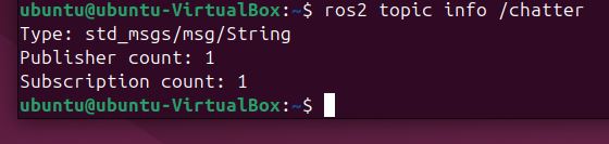
Run ros2 topic info to see the total number of publishers and subscribers for the /chatter topic:
ros2 topic info /chatterYou should see that there is one publisher and one subscriber for the /chatter topic.
Now, let’s remap the talker node to publish on a new topic called /conversation.
Stop the talker node using CTRL + C, and type this:
ros2 run demo_nodes_cpp talker --ros-args -r /chatter:=/conversationCheck the listener node terminal. You will notice that it is no longer receiving messages because it is still subscribed to the /chatter topic.
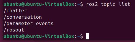
Run ros2 topic list again:
ros2 topic listYou will see the new /conversation topic in the list, but the /chatter topic is no longer present.
If you run ros2 topic echo /conversation, you will see the messages being published by the talker node on the new topic:
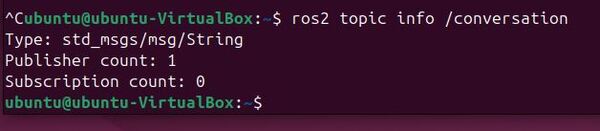
ros2 topic echo /conversationRun ros2 topic info for the /conversation topic:
ros2 topic info /conversationYou should see that there is one publisher and no subscribers for the /conversation topic.
To make the listener node receive messages from the talker node again, we need to remap its subscription from /chatter to /conversation. Stop the listener node (Ctrl+C) and run it with the remapping argument:
ros2 run demo_nodes_cpp listener --ros-args -r /chatter:=/conversationNow, the listener node will receive messages from the talker node on the remapped /conversation topic.
Run ros2 topic info for the /conversation topic again:
ros2 topic info /conversationYou should now see that there is one publisher and one subscriber for the /conversation topic.
In a Launch File
To remap topics using a launch file in ROS 2, you can use the <remap> tag within the <node> tag.
Create a new launch file called remap_demo.launch.py:
#!/usr/bin/env python3
"""
ROS 2 Topic Remapping Launch File.

This launch file demonstrates how to remap topics in ROS 2 by launching a talker and listener
node pair with remapped topic names. It shows how to change the default topic '/chatter'
to '/conversation' for both nodes.

Launch File Nodes:
    * talker_node (demo_nodes_cpp/talker): Publishes messages on remapped topic
    * listener_node (demo_nodes_cpp/listener): Subscribes to messages on remapped topic

Topic Remappings:
    * /chatter -> /conversation: Remaps the default topic to a new name for both nodes

Example Usage:
    $ ros2 launch your_package remap_demo.launch.py

:author: Addison Sears-Collins
:date: November 26, 2024
"""

# Import the necessary ROS 2 launch modules
from launch import LaunchDescription
from launch_ros.actions import Node


def generate_launch_description():
    """
    Generate a launch description for topic remapping demonstration.

    This function creates and returns a LaunchDescription object that specifies how
    to launch and configure the talker and listener nodes with topic remapping.

    Returns
    -------
    LaunchDescription
        A launch description object containing the configured nodes
    """
    return LaunchDescription([
        # Create and configure the talker node
        # This node will publish messages on the remapped topic '/conversation'
        Node(
            package='demo_nodes_cpp',      # The package containing the node
            executable='talker',           # The name of the executable
            name='talker_node',           # A unique name for this node instance
            remappings=[
                # Remap the default '/chatter' topic to '/conversation'
                ('/chatter', '/conversation'),
            ],
            output='screen'               # Display node output in the terminal
        ),

        # Create and configure the listener node
        # This node will subscribe to messages on the remapped topic '/conversation'
        Node(
            package='demo_nodes_cpp',      # The package containing the node
            executable='listener',         # The name of the executable
            name='listener_node',         # A unique name for this node instance
            remappings=[
                # Remap the default '/chatter' topic to '/conversation'
                # This must match the talker's remapping to receive messages
                ('/chatter', '/conversation'),
            ],
            output='screen'               # Display node output in the terminal
        ),
    ])
In this launch file, we define two nodes: talker and listener. For each node, we specify the package, executable, and name. We also use the remappings parameter to remap the /chatter topic to /conversation for both nodes.
To run the launch file, open a new terminal, source your ROS 2 installation, and navigate to the package containing the remap_demo.launch.py file. Then, run the following command:
ros2 launch remap_demo.launch.pyYou should see both the talker and listener nodes running, with the talker node publishing messages on the /conversation topic and the listener node subscribing to the /conversation topic.
In a new terminal, run ros2 topic list to see the available topics:
ros2 topic listYou should see the /conversation topic in the list.
To verify that the talker node is publishing messages on the /conversation topic, run ros2 topic echo:
ros2 topic echo /conversationYou should see the messages being published by the talker node.
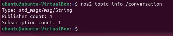
Run ros2 topic info for the /conversation topic:
ros2 topic info /conversation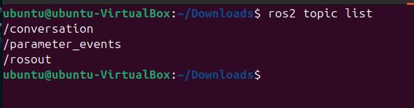
You should see that there is one publisher and one subscriber for the /conversation topic.
Using a launch file to remap topics has several advantages:
- It allows you to centralize the configuration of your nodes and their remappings in a single file.
- It makes it easier to manage complex systems with multiple nodes and remappings.
- It enables you to create reusable launch files that can be shared across different projects or with other users.
That’s it! Keep building!