Despite the explosion in the popularity of deep learning, we are still a long way from the kind of artificial general intelligence that is the inherent long term goal of computer science. Let us take a look at what the limitations are of deep learning. I’m going to pull from a paper written by Professor Gary Marcus of New York University about this topic. The paper is entitled: Deep Learning: A Critical Appraisal.
Deep Learning Methods Require Lots and Lots of Data

Humans do not need hundreds, thousands, or even millions of examples of horseshoe crabs in order to learn what a horseshoe crab is. In fact, a 3 year old child could look at one example of a horseshoe crab, be told it is a horseshoe crab, and immediately identify other horseshoe crabs, even if those new horseshoe crabs do not look exactly like that first horseshoe crab example.
Deep learning models on the other hand, need truck loads of examples of horseshoe crabs in order to distinguish horseshoe crabs from say spiders, or other similar-looking creatures.
Deep Learning Is Not Deep

The word “deep” in deep learning just refers to the structure of the mathematical model built during the training phase of the algorithm. The learning is not really deep, in the true sense of the word. A deep learning algorithm does not understand the why behind its output.
Deep Learning Does Not Quickly Adapt When Things Change

Deep learning works well when test data looks like training data. However, it cannot easily cope with novel situations, such as when the domain changes from the one that it was trained on.
For example, if a deep neural network learns that school buses are always yellow, but, all of a sudden, school buses become blue, deep learning models will need to be retrained. A five year old would have no problem recognizing the vehicle as a blue school bus.
Deep Learning Does Not Do Well With Inference
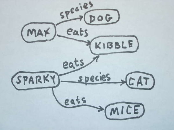
Deep learning algorithms cannot easily tell the difference between phrases like: “John promised Mary to leave” and “John promised to leave Mary.”
Deep Learning Is Not Transparent

Part of the confusion and lack of clarity of deep learning is that it is difficult to understand for the general public. For example, there are many formulas and recalculations that are completed in order to create the neural network that forms the learning model for our deep learning program.
These neural networks could also be biased depending on how the programmer sets up the formulas…for example, weighting some features more than others instead of considering the collaborative effect of all the features.
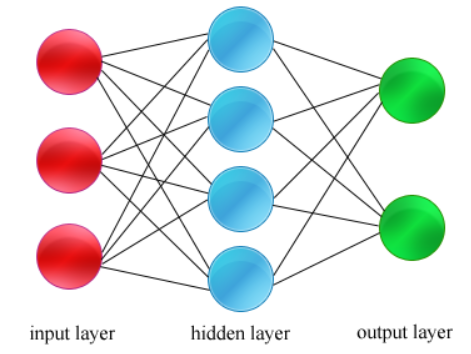
It also does not help that the layers of the neural network are called “hidden layers” which makes deep learning and its methodologies sound even more mysterious.
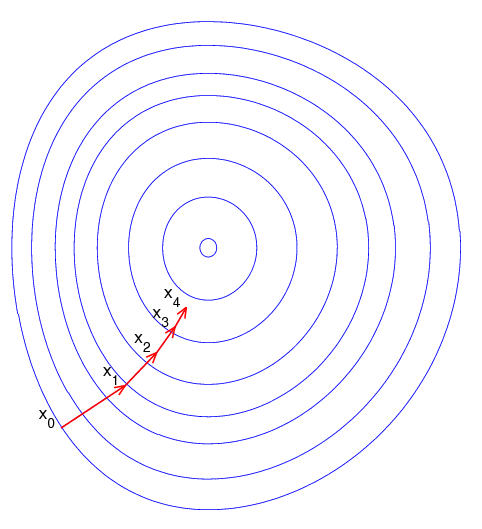
Also, the mathematics….ahh the mathematics. Try explaining the whole sigmoid and gradient descent thing to a child. Better yet, imagine a doctor explaining to a patient suffering from cancer that the cancer diagnosis was determined based on the output of an artificial feedforward neural network trained with backpropagation. How would a patient respond to this? How would a health insurance company respond?
Neural networks are relatively black boxes that look like magic to the untrained eye, containing hundreds if not millions of parameters. In fields like medicine and finance, humans want to know exactly (and simply) why a particular decision was made. You cannot just say, “because my deep neural network said so.”
Deep Learning Cannot Take Full Advantage of the Five Basic Senses

Humans have five basic senses: vision, hearing, smell, taste, touch. When I learn what a rooster is, I can see it, hear it, smell it, taste it, and touch it. Deep learning at this stage focuses mainly on the vision part and lacks the other four senses. Those other senses can be important.
For example, imagine a driverless car. A human could hear a train coming long before it sees the train. The driver would then stop. A driverless car on the other hand would need to see the train first before making the decision to stop.
Humans use all five senses to learn, and these five senses play an important role in getting a bigger picture of recognizing objects and understanding what makes a rooster a rooster, or a train, a train.
Deep Learning Is Not yet Able to Know Something With 100% Certainty

I could look at a trash can inside my kitchen, know it is a trash can, and tell you with 100% certainty that it is a trash can. A deep neural network on the other hand, no matter how many parameters or data it has been trained on, works in the world of probabilities and numbers. It will never have 100% confidence that the trash can is a trash can.
A trained deep neural network, for example, might be 96.3% sure it is a trash can but not 100% sure. There is always that miniscule probability it could be something else, like say a tree stump or a recycle bin.
I’m in front of my laptop now. It is 100% my laptop. A deep learning algorithm, on the other hand, might say it is 99.3% sure that the object currently in front of me is my laptop. It would need a human to validate that the object is, in fact, a laptop.
This limitation this has to do with the way a neural network algorithm “learns.”
The reality is that a program does not look at a dog and intuitively know that it is a dog like a human does. Instead, deep learning is more like a statistical analysis of patterns that are observed from the sample data points. So a deep learning program might only identify that an image is a dog based on the shapes in the image and the fact that statistical patterns tell you that these shapes will mean that the image is likely a dog.
But the fact is that the deep learning program cannot be 100% sure that an image is a dog; for example if there is a weird picture of a fox or bear that looks a lot like a dog. Due to this uncertainty (the fact that the deep learning algorithm cannot be 100% sure), it is difficult for humans to trust deep learning especially when applied to critical, possibly life-threatening applications.
For example, if a deep learning algorithm cannot always correctly identify that an object is an obstacle when processing the images from a driverless car, then it would be concerning for people to trust this program to drive for us.
Furthermore, there may be an inherent bias in how the deep learning algorithm identifies patterns. For example, if a programmer decided that a road is only definable by separating lines for lanes, then the algorithm may be biased to using lines for identifying roads. This would mean that the algorithm misses identifying roads that don’t have clear lane markings or even dirt roads. Such a bias means that a deep learning program could miss important identifying features/patterns.

In short, it is difficult for a deep learning algorithm to account for every possible example and every variation, which means that it would not be 100% correct.

