In this tutorial, we are going to learn advanced concepts for object-oriented programming using Python.
Prerequisites
- You have completed this tutorial: How to Read and Write Files in Python
Writing Getters and Setters
Let’s learn about getters and setters – they’re like security guards for your robot’s information! Think of them as special functions that help you safely check and change your robot’s settings.
Just like you wouldn’t want anyone to accidentally set your robot’s speed to a dangerous level, getters and setters help protect your robot’s information and make sure it’s changed in the right way.
First, create a file called robot_settings.py inside the following folder: ~/Documents/python_tutorial.
Define a class named Robot that will help us manage the speed and battery level, which are common attributes in robotics:
class Robot:
    def __init__(self, speed=0, battery=100):
        self._speed = speed
        self._battery = battery

    def get_speed(self):
        return self._speed

    def set_speed(self, value):
        if value < 0:
            raise ValueError("Speed cannot be negative")
        self._speed = value

    def get_battery(self):
        return self._battery

    def set_battery(self, value):
        if not (0 <= value <= 100):
            raise ValueError("Battery must be between 0 and 100")
        self._battery = value
This code snippet introduces get and set methods for speed and battery level. The setters include validations to ensure the values are within acceptable ranges, which is essential for maintaining the safety and functionality of your robot.
Next, run a simple test to see these getters and setters in action.
Add the following test code at the end of your script:
robot = Robot()
print("Initial Speed:", robot.get_speed())
robot.set_speed(5)
print("Updated Speed:", robot.get_speed())

try:
    robot.set_battery(150)
except ValueError as e:
    print(e)
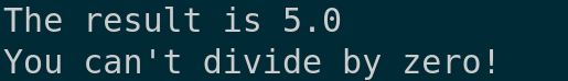
Now, run the code:
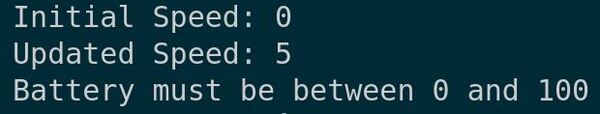
You should see the outputs corresponding to the robot’s speed updates and any error messages related to battery level adjustments.
Using Inheritance
Let’s talk about inheritance in Python, a topic we briefly covered in the previous tutorial.
Inheritance is like creating a family tree of robots. Imagine you design a basic robot with common features. Then, just like how children inherit traits from their parents, you can create new types of robots that automatically get all the abilities of the basic robot, plus their own special features. This saves you from having to write the same code over and over again.
Create a new file called robot_inheritance.py inside the following folder: ~/Documents/python_tutorial.
Begin by defining a base class called Robot that will contain common attributes and methods that any robot might need:
class Robot:
    def __init__(self, name):
        self.name = name

    def greet(self):
        print(f"Hello, I am {self.name}.")
Now, let’s use inheritance to create a specialized type of robot. We’ll define a class CleaningRobot that inherits from Robot:
class CleaningRobot(Robot):
    def clean(self):
        print("Cleaning in progress...")
Notice how CleaningRobot doesn’t redefine the __init__ method or the greet method but inherits them from the Robot class. It does, however, add a new method, clean, which is specific to cleaning robots.
Now let’s add this test code at the end of your script to create an instance of CleaningRobot and use its methods:
my_robot = CleaningRobot("RoboCleaner")
my_robot.greet()
my_robot.clean()
Now, run the script.
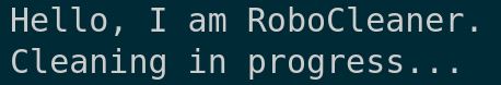
You should see the greeting from the robot followed by the cleaning message. This demonstrates how the CleaningRobot uses functionality from the Robot base class while adding its own unique behavior.
Practicing Polymorphism
Let’s take a look at another key concept in object-oriented programming: polymorphism.
Polymorphism literally means “many forms”.
Imagine you have a television remote control with a “power” button that works on different TVs. Just like how different television classes (Samsung, LG, or Sony) all understand the same power command, different robot classes can share common commands too. This is polymorphism in action – we can treat different kinds of objects (like our different robot types) as if they were the same basic type (like a general “robot” class).
For example, all our robots might understand the command “move forward,” but each robot class implements it differently: a walking robot takes steps, while a wheeled robot rolls forward. Same command name, different behaviors!
Create a new file named polymorphism_example.py inside the following folder: ~/Documents/python_tutorial.
Start by defining a base class called Robot with the following method:
class Robot:
    def __init__(self, name):
        self.name = name

    def perform_task(self):
        print(f"{self.name} performs a generic task.")
Now, let’s define two subclasses that inherit from Robot but perform tasks differently, demonstrating polymorphism:
class CleaningRobot(Robot):
    def perform_task(self):
        print(f"{self.name} is cleaning the area.")

class PaintingRobot(Robot):
    def perform_task(self):
        print(f"{self.name} is painting the wall.")
Each subclass has its own implementation of the perform_task method, tailored to what the specific robot is supposed to do.
Now add this test code at the end of your script to create instances of each robot and call their task method:
robots = [CleaningRobot("Cleany"), PaintingRobot("Painty")]
for robot in robots:
    robot.perform_task()
Now, run the script.
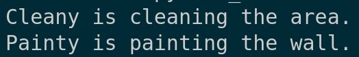
You should see each robot performing its specific task, demonstrating how polymorphism allows us to use a common method in different contexts.
Working with Magic Methods
Now let’s explore a concept of Python programming that can significantly enhance your coding, especially when working with classes in robotics: magic methods, also known as dunder methods.
Magic methods are special methods that start and end with double underscores. They allow us to implement functionality that mimics the behavior of built-in types and elegantly interact with different Python operations.
Create a new file named magic_methods.py inside the following folder: ~/Documents/python_tutorial.
We’ll begin by defining a class called Robot that utilizes some common magic methods:
class Robot:
    def __init__(self, name, battery_life):
        self.name = name
        self.battery_life = battery_life

    def __str__(self):
        return f"{self.name} (Battery life: {self.battery_life} hours)"

    def __len__(self):
        return self.battery_life

    def __add__(self, other):
        if isinstance(other, Robot):
            return Robot(f"{self.name}&{other.name}", self.battery_life + other.battery_life)
        raise ValueError("Can only add another Robot")
In this snippet, we define three magic methods:
__str__: customizes the string representation of our objects, making it more informative.
__len__: allows us to use Python’s len() function to get the battery life of the robot.
__add__: enables us to “add” two robots together to create a new robot with combined names and battery life.
Now add the following test code at the end of your script:
robot1 = Robot("Robo-One", 5)
robot2 = Robot("Robo-Two", 3)
print(robot1)
print("Battery life of", robot1.name, "is", len(robot1), "hours")
combined_robot = robot1 + robot2
print(combined_robot)
Run your code.
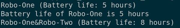
You should see the string representations of the robots, their individual battery lives, and the details of the combined robot.
That concludes our overview of magic methods. Thanks, and I’ll see you in the next tutorial.
Keep building!