In this tutorial, we are going to dive into the world of functions in Python, an essential skill in your journey toward becoming a robotics engineer. Functions allow us to encapsulate code into reusable blocks, making our programs more modular, maintainable, and testable—qualities crucial in robotics software development.
Prerequisites
- You have completed this tutorial: How to Process User Input and Strings in Python.
Using Functions
Let’s start by defining what a function is in Python. A function is a set of instructions that performs a specific task; it can take inputs, execute code, and return an output. To create a function, we use the def keyword followed by the function name and parentheses.
Let’s start by opening your code editor and creating a new file named robot_functions.py inside the following folder: ~/Documents/python_tutorial.
Let’s define a function called greet. This function will take a name as an input and print a greeting message. Here’s how you do it:
def greet(name):
    print(f"Hello, {name}! Welcome to the robotics world.")
Here, name is a parameter of the function greet. The code inside the function will output a personalized greeting message when it is called.
Now let’s see this function in action. Below the function definition, call the function by passing a name:
greet("Addison")
After typing this, save your file, and run it.
You should see this output:

This example demonstrates how your function takes an input and processes it to return a result.
Understanding Lambda Functions
Let’s explore lambda functions in Python. Lambda functions are small anonymous functions defined with the lambda keyword. They are syntactically restricted to a single expression. This makes them very useful for simple functionalities that don’t require extensive formatting in robotics programming.
In robotics, lambda functions can be particularly useful for handling events or data transformations quickly without needing to create separate, named functions. This can help keep your code clean and efficient, which is vital in complex robotic systems where performance is a priority.
Let’s start by opening your code editor and creating a new file named lambda_functions.py inside the following folder: ~/Documents/python_tutorial.
Create a lambda function that multiplies two numbers. Here’s how you do it in your editor:
multiply = lambda x, y: x * y
This lambda function takes two arguments, x and y, and returns their product. The expression after the colon is what the function will return when called.
Now, let’s use this function by calling it with two numbers:
result = multiply(4, 5)
print(f"The product is {result}")
You should see the output:
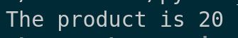
This demonstrates how our lambda function quickly processes inputs and provides outputs without the need for defining a conventional function.
Working with Maps
Let’s explore how to work with Python’s built-in map function. This is a tool that applies a function to every item in an iterable, such as a list or tuple, and returns a map object, which is an iterator. This can be particularly useful in robotics for transforming data efficiently.
Whether it’s sensor data or commands to actuators, using map can help you manage data transformations cleanly and effectively across various components of your robotic systems.
Let’s start by understanding the syntax of the map function. The basic structure is map(function, iterable), where function is the function that you want to apply to each item in the iterable.
Create a file called convert_temperatures.py inside the following folder: ~/Documents/python_tutorial.
First, we’ll define a simple function that we will use with map. Let’s create a function that converts temperatures from Celsius to Fahrenheit:
def celsius_to_fahrenheit(c):
    return (c * 9/5) + 32
This function takes a Celsius value, converts it to Fahrenheit, and returns the result. It’s a simple calculation but imagine needing to convert a list of temperatures—this is where map comes in handy.
Now, let’s use the map function to apply our celsius_to_fahrenheit function to a list of temperatures:
temperatures_celsius = [0, 20, 30, 40]
temperatures_fahrenheit = list(map(celsius_to_fahrenheit, temperatures_celsius))
Let’s print out the Fahrenheit temperatures:
print(temperatures_fahrenheit)
Now, save your script, and run it.

You should see the output as a list of temperatures in Fahrenheit. This demonstrates how the map function has applied our conversion function to each element in the list efficiently.
Creating Filters
Let’s learn how to use the filter function in Python.
Filter is a built-in function that offers a convenient way to filter items from an iterable—like lists or tuples—based on a function that tests each item in the iterable to be true or not. This functionality is incredibly useful in robotics for extracting relevant data from a larger dataset, such as sensor readings or logs.
The syntax for the filter function is:
filter(function, iterable)
Here, function is a function that tests each item in the iterable to determine if it should be included in the result.
Create a file called filter_even_numbers.py inside the following folder: ~/Documents/python_tutorial.
Let’s define a function that checks if a number is even. This function will return True if the number is even, which tells the filter to include it in the output:
def is_even(num):
    return num % 2 == 0
This function uses the modulo operator % to check if the number has no remainder when divided by 2, meaning it’s even.
Now, let’s apply this function to a list of numbers using filter:
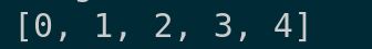
numbers = [1, 2, 3, 4, 5, 6, 7, 8, 9, 10]
even_numbers = list(filter(is_even, numbers))
Let’s print out the even numbers:
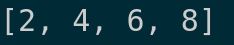
print(even_numbers)
Save your script, and run it.
You should see this output:
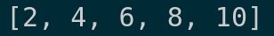
This list contains all the even numbers from our original list, filtered using our is_even function.
In robotics, you might use filters to process sensor data, like filtering out readings that are beyond a certain threshold or that don’t meet certain conditions. This helps in focusing on relevant data and reducing noise in the system’s input, which is crucial for performance and accuracy.
Working with the Reduce Function
Now let’s explore the reduce function in Python, which is a fundamental tool for performing cumulative operations on a list or any iterable.
Unlike map and filter, reduce doesn’t come built into the basic set of Python functions; it is part of the functools module, emphasizing its utility for more specialized tasks, such as aggregating data values in a sequence.
To use reduce, you first need to import it from the functools module. Let’s do that and explore how reduce works.
Create a file named reduce_example.py inside the following folder: ~/Documents/python_tutorial.
Type this code:
from functools import reduce
The reduce function applies a given function to the items of an iterable, cumulatively, to reduce the iterable to a single value. This function takes two arguments at a time and continues to combine them until only one remains.
Let’s define a simple operation to use with reduce: a function that multiplies two numbers. This will help us calculate the product of a list of numbers:
def multiply(x, y):
    return x * y
Now, let’s use reduce to multiply all the numbers in a list together:
numbers = [1, 2, 3, 4, 5]
product = reduce(multiply, numbers)
Let’s print out the result of multiplying all these numbers:
print(f"The product of the numbers is: {product}")
Run the script.
You should see the output:

This shows how reduce took our list of numbers and reduced them to a single value by multiplying them together sequentially.
- First iteration:
- Takes first two numbers: 1 and 2
- multiply(1, 2) = 2
- Result so far: 2
- Second iteration:
- Takes previous result (2) and next number (3)
- multiply(2, 3) = 6
- Result so far: 6
- Third iteration:
- Takes previous result (6) and next number (4)
- multiply(6, 4) = 24
- Result so far: 24
- And so on…
In robotics, reduce can be useful for processing sequences of data to extract single cumulative values, like summing up sensor measurements to calculate an average or total over time, or combining a series of incremental movements into a total displacement.
That’s it for this tutorial on the reduce function.
Thanks, and I’ll see you in the next tutorial.
Keep building!