In this tutorial, we will create a ROS 2 action. A ROS 2 action is a communication interface that allows a node to send a goal to another node to perform a long-running task and receive feedback while the task is in progress and a result when the task is completed.
You will build this by the end of this tutorial:
A ROS 2 action is useful for tasks that take a while to complete and where you want to know the progress and be able to cancel the task if needed. Let’s take a look at some real-world examples.
Real-World Applications
- Robot Vacuum Cleaner: Consider a robot vacuum cleaner. Instead of just starting to clean, let’s say we want to clean a specific room. This might take some time, and we want to get updates on the cleaning progress. We create an action called clean_room. This action will give us updates like “10% complete”, “50% complete”, and “finished”, and we can even cancel the cleaning if we change our mind.
- Autonomous Docking to a Charging Station: Consider a mobile robot that needs to autonomously dock to recharge its batteries. This process involves multiple steps and precise positioning. We create an action called dock_to_charger. The action provides continuous feedback about the robot’s progress, such as “approaching charging station”, “aligning with dock”, “making final approach”, and “charging connection established”. The operation can be cancelled if obstacles are detected or if alignment fails. This is particularly useful because docking requires careful coordination and monitoring – the robot needs to detect the charging station, align itself precisely, and verify a successful connection, all while providing status updates and handling potential failures.
- Kitchen Robot Chef: Imagine a mobile robot with an arm that prepares meals in a kitchen. The robot needs to move around, grab ingredients, and use cooking equipment. We create an action called prepare_dish. This action provides feedback like “getting ingredients”, “chopping vegetables”, “stirring pot”, and “plating food”. The cooking process can be cancelled if ingredients are missing or if safety limits are exceeded.
When to Use Actions vs. Publishers and Subscribers?
Publishers and subscribers are the basic tools for continuous, one-way communication in ROS 2. For example, a temperature sensor constantly publishing the current temperature or a motor constantly receiving speed commands.
However, sometimes we need to monitor the progress of a long-running task and have the ability to cancel it if needed. ROS 2 actions work well for this use case.
Prerequisites
All my code for this project is located here on GitHub.
Create a Package
Navigate to the ~/ros2_ws/src/yahboom_rosmaster directory and create the yahboom_rosmaster_msgs package.
cd ~/ros2_ws/src/yahboom_rosmaster
ros2 pkg create --build-type ament_cmake \
                --license BSD-3-Clause \
                --maintainer-name ubuntu \
                --maintainer-email automaticaddison@todo.com \
                yahboom_rosmaster_msgs
Format of an Action
In ROS 2, an action is defined in a .action file, which consists of three parts:
- The goal (what you want to happen)
- The result (what happened in the end)
- The feedback (updates while it’s happening)
Each part is separated by a line with three dashes (—).
# Goal (Request)
---
# Result
---
# Feedback
The first part, the goal message, describes exactly what you want the robot or system to do. Think of it like giving instructions to someone – you need to be clear about what you want.
The second part, the result message, tells you what happened after everything is done. It’s like getting a report card after finishing a task – it shows the final outcome.
The third part, the feedback message, gives you regular updates while the action is running. Imagine tracking a package delivery – you get updates like “package picked up”, “in transit”, “out for delivery”.
When you use an action, it works like this: First, you (the action client) send your request (goal). Then, the system that handles the task (action server) starts working on it and sends you progress updates (feedback) so you know what’s happening. When it’s all done, you get the final report (result) telling you how everything went.
Define the Action
Let’s create a file called TimedRotation.action that defines an action for performing a timed rotation (of a mobile robot) with a specified angular velocity and duration, providing feedback on the progress and status of the rotation, and returning the result indicating the success and actual duration of the rotation.
Open a terminal window, and type:
cd ~/ros2_ws/src/yahboom_rosmaster/yahboom_rosmaster_msgs
mkdir action && cd action
Within the action directory, create a file called TimedRotation.action with the following contents:
# Request parameters for the timed rotation
float64 angular_velocity    # Desired angular velocity in rad/s (positive for counterclockwise, negative for clockwise)
float64 duration           # Desired duration of the rotation in seconds
---
# Result of the completed rotation
bool success               # Indicates if the rotation was completed successfully
float64 actual_duration    # Actual duration of the rotation in seconds
---
# Continuous feedback during rotation
float64 elapsed_time  # Elapsed time since the start of the rotation in seconds
string status         # Current status of the rotation:
                      # GOAL_RECEIVED: The action server has received a goal
                      # ROTATING: The rotation is in progress
                      # GOAL_SUCCEEDED: The rotation has been completed successfully
                      # GOAL_ABORTED: The rotation has been aborted due to an error or exceptional condition
                      # GOAL_CANCELED: The client has canceled the rotation goal
The goal message includes the desired angular velocity (in radians per second) and the duration of the rotation (in seconds).
The feedback message provides information about the progress of the rotation, including the elapsed time since the start of the rotation and the current status of the rotation, which can be one of the following: GOAL_RECEIVED, ROTATING, GOAL_SUCCEEDED, GOAL_ABORTED, or GOAL_CANCELED.
The result message indicates whether the rotation was completed successfully and provides the actual duration of the rotation.
Edit CMakeLists.txt
Here’s the complete CMakeLists.txt file with the necessary additions to include the TimedRotation.action in your ROS 2 package:
cmake_minimum_required(VERSION 3.8)
project(yahboom_rosmaster_msgs)

if(CMAKE_COMPILER_IS_GNUCXX OR CMAKE_CXX_COMPILER_ID MATCHES "Clang")
  add_compile_options(-Wall -Wextra -Wpedantic)
endif()

# find dependencies
find_package(ament_cmake REQUIRED)
find_package(rosidl_default_generators REQUIRED)

rosidl_generate_interfaces(${PROJECT_NAME}
  "action/TimedRotation.action"
)

if(BUILD_TESTING)
  find_package(ament_lint_auto REQUIRED)
  # the following line skips the linter which checks for copyrights
  # comment the line when a copyright and license is added to all source files
  set(ament_cmake_copyright_FOUND TRUE)
  # the following line skips cpplint (only works in a git repo)
  # comment the line when this package is in a git repo and when
  # a copyright and license is added to all source files
  set(ament_cmake_cpplint_FOUND TRUE)
  ament_lint_auto_find_test_dependencies()
endif()

ament_package()
Edit package.xml
Add the necessary dependencies to your package.xml file:
<?xml version="1.0"?>
<?xml-model href="http://download.ros.org/schema/package_format3.xsd" schematypens="http://www.w3.org/2001/XMLSchema"?>
<package format="3">
  <name>yahboom_rosmaster_msgs</name>
  <version>0.0.0</version>
  <description>Custom messages, services, and actions for the Yahboom ROSMaster robot</description>
  <maintainer email="automaticaddison@todo.com">ubuntu</maintainer>
  <license>BSD-3-Clause</license>

  <buildtool_depend>ament_cmake</buildtool_depend>
  <buildtool_depend>rosidl_default_generators</buildtool_depend>

  <exec_depend>rosidl_default_runtime</exec_depend>

  <test_depend>ament_lint_auto</test_depend>
  <test_depend>ament_lint_common</test_depend>

  <member_of_group>rosidl_interface_packages</member_of_group>

  <export>
    <build_type>ament_cmake</build_type>
  </export>
</package>
Build the action
Open a terminal window, and type:
cd ~/ros2_ws
rosdep install --from-paths src --ignore-src -y
colcon build && source ~/.bashrc
Or you can type the following command if you have been following my tutorials:
build
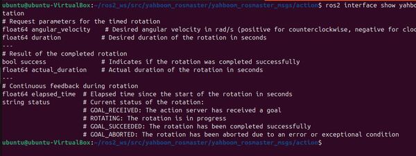
Check the action definition exists:
ros2 interface show yahboom_rosmaster_msgs/action/TimedRotation
If the action definition exists and is properly generated, the command will display the contents of the TimedRotation.action file, like this:
If the action definition doesn’t exist or is not properly generated, you will see an error message indicating that the interface could not be found.
Writing an Action Server
Let’s write an action server node in C++. This node will handle long-running tasks with feedback and the ability to cancel the task while it’s running. We will follow the official ROS 2 examples.
The server should publish to the /mecanum_drive_controller/cmd_vel topic to control the robot’s rotation. The action server receives the goal from the action client, which specifies the desired angular velocity and duration for the rotation.
The server then publishes velocity commands to the /mecanum_drive_controller/cmd_vel topic to execute the rotation. Here’s an explanation of the action server’s behavior:
- The action server subscribes to the action topic to receive goals from the action client.
- When a goal is received, the action server extracts the desired angular velocity and duration from the goal message.
- The action server publishes velocity commands to the /mecanum_drive_controller/cmd_vel topic to initiate and maintain the robot’s rotation. It sets the linear velocities (in both the x and y directions) to zero and the angular velocity around z to the specified value from the goal.
- While the rotation is in progress, the action server publishes feedback messages to the action topic, providing the elapsed time since the start of the rotation and the status.
- The action server continues publishing velocity commands to the /mecanum_drive_controller/cmd_vel topic until the specified duration is reached.
- Once the duration is reached, the action server stops publishing velocity commands and sends a result message to the action topic, indicating the success of the rotation and the actual duration of the rotation.
- If any errors occur during the rotation, the action server stops publishing velocity commands and sends a result message indicating the failure.
Open a terminal window, and type:
cd ~/ros2_ws/src/yahboom_rosmaster/yahboom_rosmaster_system_tests/src
Create a new file called timed_rotation_action_server.cpp.
Add the following code:
/**
 * @file timed_rotation_action_server.cpp
 * @brief This ROS 2 node implements an action server for the TimedRotation action.
 *
 * This program implements a ROS 2 action server that executes timed rotation actions for the Yahboom RosMaster robot.
 * It receives goals from action clients, publishes timestamped velocity commands to rotate the robot,
 * and provides feedback on the rotation progress.
 *
 * Subscription Topics:
 *   None
 *
 * Publishing Topics:
 *   /mecanum_drive_controller/cmd_vel (geometry_msgs/TwistStamped):
 *     Timestamped velocity command for the robot:
 *     - header.stamp: Current ROS time when command is published
 *     - header.frame_id: "base_link" (robot's base frame)
 *     - twist.linear.x: Always 0 (no forward/backward motion)
 *     - twist.linear.y: Always 0 (no left/right motion)
 *     - twist.angular.z: Rotation speed in radians/second (positive=counterclockwise, negative=clockwise)
 *
 * Action Server:
 *   timed_rotation (yahboom_rosmaster_msgs/action/TimedRotation):
 *     Executes timed rotation actions with the following:
 *     - Goal: angular_velocity (rad/s) and duration (seconds)
 *     - Feedback: elapsed_time and status updates
 *     - Result: success flag and actual_duration
 *
 * @author Addison Sears-Collins
 * @date November 25, 2024
 */

#include <memory>
#include <thread>
#include <chrono>

#include "rclcpp/rclcpp.hpp"
#include "rclcpp_action/rclcpp_action.hpp"
#include "yahboom_rosmaster_msgs/action/timed_rotation.hpp"
#include "geometry_msgs/msg/twist_stamped.hpp"

using namespace std::chrono_literals;
using TimedRotation = yahboom_rosmaster_msgs::action::TimedRotation;
using GoalHandleTimedRotation = rclcpp_action::ServerGoalHandle<TimedRotation>;

/**
 * @class TimedRotationActionServer
 * @brief ROS 2 action server for the TimedRotation action.
 *
 * This class implements the action server functionality for the TimedRotation action.
 * It receives goals from an action client, executes the timed rotation, provides feedback,
 * and handles goal cancellation requests. The server maintains rotation by continuously
 * publishing timestamped velocity commands until the specified duration is reached or the goal is canceled.
 */
class TimedRotationActionServer : public rclcpp::Node
{
public:
  /**
   * @brief Constructor for the TimedRotationActionServer class.
   *
   * Initializes the action server and the timestamped velocity command publisher.
   * Sets up callback bindings for handling goals, cancellation requests,
   * and accepted goals.
   */
  TimedRotationActionServer()
  : Node("timed_rotation_action_server_cpp")
  {
    using namespace std::placeholders;

    // Create the action server with callbacks for goal handling, cancellation, and execution
    action_server_ = rclcpp_action::create_server<TimedRotation>(
      this,
      "timed_rotation",
      std::bind(&TimedRotationActionServer::handle_goal, this, _1, _2),
      std::bind(&TimedRotationActionServer::handle_cancel, this, _1),
      std::bind(&TimedRotationActionServer::handle_accepted, this, _1));

    // Create publisher for timestamped velocity commands
    cmd_vel_publisher_ = this->create_publisher<geometry_msgs::msg::TwistStamped>(
      "/mecanum_drive_controller/cmd_vel",
      10);  // Queue size of 10 messages
  }

private:
  // Class member variables
  rclcpp_action::Server<TimedRotation>::SharedPtr action_server_;  ///< The action server instance
  rclcpp::Publisher<geometry_msgs::msg::TwistStamped>::SharedPtr cmd_vel_publisher_;  ///< Publisher for timestamped velocity commands

  /**
   * @brief Callback function for handling new goal requests.
   *
   * This function is called when a new goal is received from an action client.
   * Currently accepts all goals without any validation.
   *
   * @param uuid Unique identifier for the goal request.
   * @param goal The goal request message containing angular_velocity and duration.
   * @return rclcpp_action::GoalResponse indicating if the goal is accepted or rejected.
   */
  rclcpp_action::GoalResponse handle_goal(
    const rclcpp_action::GoalUUID & uuid,
    [[maybe_unused]] std::shared_ptr<const TimedRotation::Goal> goal)
  {
    RCLCPP_INFO(this->get_logger(), "Received goal request for a timed rotation action");
    (void)uuid;
    return rclcpp_action::GoalResponse::ACCEPT_AND_EXECUTE;
  }

  /**
   * @brief Callback function for handling cancel requests.
   *
   * This function is called when a client requests to cancel an ongoing goal.
   * Currently accepts all cancellation requests.
   *
   * @param goal_handle The goal handle associated with the goal to be canceled.
   * @return rclcpp_action::CancelResponse indicating if the cancellation is accepted.
   */
  rclcpp_action::CancelResponse handle_cancel(
    const std::shared_ptr<GoalHandleTimedRotation> goal_handle)
  {
    RCLCPP_INFO(this->get_logger(), "Received cancel request for timed rotation action");
    (void)goal_handle;
    return rclcpp_action::CancelResponse::ACCEPT;
  }

  /**
   * @brief Callback function for handling accepted goals.
   *
   * This function is called when a goal has been accepted and needs to be executed.
   * Spawns a new thread to execute the goal to avoid blocking the main thread.
   *
   * @param goal_handle The goal handle associated with the accepted goal.
   */
  void handle_accepted(const std::shared_ptr<GoalHandleTimedRotation> goal_handle)
  {
    // Create a new thread using proper bind syntax
    std::thread{
      [this, goal_handle]() {
        this->execute(goal_handle);
      }
    }.detach();
  }

  /**
   * @brief Executes the timed rotation action.
   *
   * This function runs in a separate thread and performs the following:
   * 1. Publishes initial feedback with GOAL_RECEIVED status
   * 2. Creates and sends timestamped velocity commands based on goal parameters
   * 3. Continuously publishes feedback during rotation
   * 4. Handles cancellation requests during execution
   * 5. Stops rotation and publishes final result
   *
   * @param goal_handle The goal handle associated with the goal to be executed.
   */
  void execute(const std::shared_ptr<GoalHandleTimedRotation> goal_handle)
  {
    RCLCPP_INFO(this->get_logger(), "Executing goal for timed rotation action...");

    // Get the goal message
    const auto goal = goal_handle->get_goal();

    // Create result and feedback messages
    auto result = std::make_shared<TimedRotation::Result>();
    auto feedback = std::make_shared<TimedRotation::Feedback>();

    // Send initial feedback
    feedback->status = "GOAL_RECEIVED";
    goal_handle->publish_feedback(feedback);

    // Create timestamped velocity command message
    geometry_msgs::msg::TwistStamped twist_stamped_msg;
    twist_stamped_msg.twist.angular.z = goal->angular_velocity;  // Set rotation speed
    twist_stamped_msg.header.frame_id = "base_link";  // Set the reference frame
    // linear.x and linear.y are automatically initialized to 0

    // Record start time for duration tracking
    auto start_time = this->now();

    // Main execution loop
    while (rclcpp::ok())
    {
      // Check for cancellation requests
      if (goal_handle->is_canceling())
      {
        goal_handle->canceled(result);
        RCLCPP_INFO(this->get_logger(), "Goal canceled");
        feedback->status = "GOAL_CANCELED";
        goal_handle->publish_feedback(feedback);

        // Stop the robot with timestamped command
        twist_stamped_msg.twist.angular.z = 0.0;
        twist_stamped_msg.header.stamp = this->now();
        cmd_vel_publisher_->publish(twist_stamped_msg);
        return;
      }

      // Update timestamp and publish velocity command
      twist_stamped_msg.header.stamp = this->now();
      cmd_vel_publisher_->publish(twist_stamped_msg);

      // Calculate elapsed time
      auto elapsed_time = (this->now() - start_time).seconds();

      // Publish feedback
      feedback->elapsed_time = elapsed_time;
      feedback->status = "ROTATING";
      goal_handle->publish_feedback(feedback);

      // Check if we've reached the desired duration
      if (elapsed_time >= goal->duration)
      {
        break;
      }

      // Sleep to control update rate (5Hz)
      std::this_thread::sleep_for(200ms);
    }

    // Stop the robot with final timestamped command
    twist_stamped_msg.twist.angular.z = 0.0;
    twist_stamped_msg.header.stamp = this->now();
    cmd_vel_publisher_->publish(twist_stamped_msg);

    // Set and send result
    result->success = true;
    result->actual_duration = (this->now() - start_time).seconds();

    // Mark the goal as succeeded
    goal_handle->succeed(result);

    // Send final feedback
    feedback->status = "GOAL_SUCCEEDED";
    goal_handle->publish_feedback(feedback);

    RCLCPP_INFO(this->get_logger(), "Goal succeeded");
  }
};

/**
 * @brief Main function for the timed rotation action server node.
 *
 * Initializes ROS 2, creates an instance of the TimedRotationActionServer,
 * and spins the node to process callbacks.
 *
 * @param argc Number of command-line arguments.
 * @param argv Array of command-line arguments.
 * @return int Exit status of the program.
 */
int main(int argc, char ** argv)
{
  rclcpp::init(argc, argv);
  auto action_server = std::make_shared<TimedRotationActionServer>();
  rclcpp::spin(action_server);
  rclcpp::shutdown();
  return 0;
}
Save the code and close the editor.
Edit your package.xml file.
cd ~/ros2_ws/src/yahboom_rosmaster/yahboom_rosmaster_system_tests
Open the package.xml file.
Save the file and close the editor.
Open CMakeLists.txt.
Make sure your CMakeLists.txt file looks like this.
Save the file, and close the editor.
Build the workspace:
build
Testing the Action Server
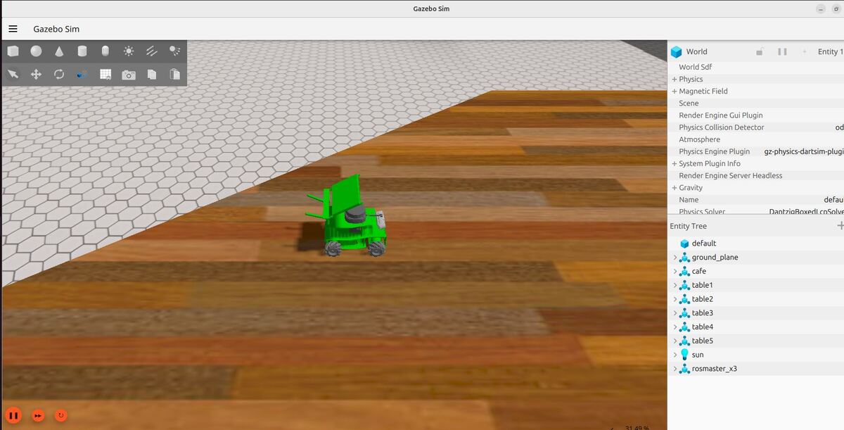
Now let’s launch the mobile robot.
Open a terminal window, and type the following command:
x3
or
bash ~/ros2_ws/src/yahboom_rosmaster/yahboom_rosmaster_bringup/scripts/rosmaster_x3_gazebo.sh
Now, let’s launch the action server. Open a new terminal window, and type:
ros2 run yahboom_rosmaster_system_tests timed_rotation_action_server
To see the list of actions a node provides, /timed_rotation_action_server in this case, open a new terminal and run the command:
ros2 node info /timed_rotation_action_server_cpp
Which will return a list of /timed_rotation_action_server_cpp’s subscribers, publishers, services, action servers and action clients:
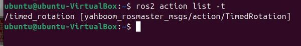
Let’s see all the active actions:
ros2 action list -t
If you want to check the action type for the action, run the command:
ros2 action type /timed_rotation
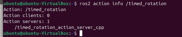
Take a closer look at the action with this command:
ros2 action info /timed_rotation
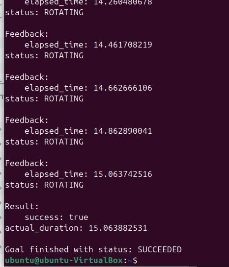
To send a goal to the server and receive feedback, type:.
ros2 action send_goal /timed_rotation yahboom_rosmaster_msgs/action/TimedRotation "{duration: 15.0, angular_velocity: -0.25}" --feedback
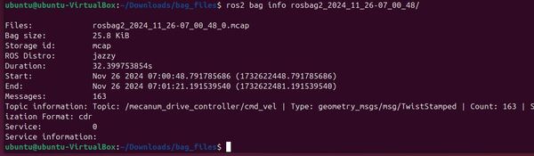
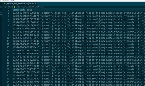
Observe the velocity messages:
ros2 topic echo /mecanum_drive_controller/cmd_vel
The robot will rotate for 15 seconds.
Press CTRL + C in all windows to close everything.
Writing an Action Client
Now that we’ve created and tested our action server for controlling the robot’s rotation, let’s create an action client that can send goals to it. The action client will allow us to programmatically request timed rotations, monitor their progress through feedback, and receive the final results. This is particularly useful when you want to integrate the rotation behavior into a larger automated system or control sequence.
Open a terminal window and navigate to the src directory of your package:
cd ~/ros2_ws/src/yahboom_rosmaster/yahboom_rosmaster_system_tests/src
Create a new file named timed_rotation_action_client.cpp and open it in your preferred text editor:
Add the following code to timed_rotation_action_client.cpp:
/**
 * @file timed_rotation_action_client.cpp
 * @brief ROS 2 action client node for sending timed rotation goals.
 *
 * This program implements a ROS 2 action client node that sends timed rotation goals
 * to a corresponding action server. It subscribes to the /timed_rotation_mode topic
 * to determine when to send or cancel goals.
 *
 * Subscription Topics:
 *   /timed_rotation_mode (std_msgs/Bool): Topic indicating whether timed rotation mode is active
 *
 * Publishing Topics:
 *   None
 *
 * Action Client:
 *   timed_rotation (yahboom_rosmaster_msgs/action/TimedRotation):
 *     Sends goals for timed rotation and receives feedback and results:
 *     - Goal: angular_velocity (rad/s) and duration (seconds)
 *     - Feedback: elapsed_time (seconds) and status string
 *     - Result: success flag and actual_duration (seconds)
 *
 * @author Addison Sears-Collins
 * @date November 25, 2024
 */

#include <memory>
#include <thread>

#include "rclcpp/rclcpp.hpp"
#include "rclcpp_action/rclcpp_action.hpp"
#include "yahboom_rosmaster_msgs/action/timed_rotation.hpp"
#include "std_msgs/msg/bool.hpp"

using TimedRotation = yahboom_rosmaster_msgs::action::TimedRotation;
using GoalHandleTimedRotation = rclcpp_action::ClientGoalHandle<TimedRotation>;

/**
 * @class TimedRotationActionClient
 * @brief ROS 2 action client node for sending timed rotation goals.
 *
 * This class implements a ROS 2 action client that sends timed rotation goals and
 * processes feedback and results from the action server. It can be controlled via
 * a boolean topic to start and stop rotations.
 */
class TimedRotationActionClient : public rclcpp::Node
{
public:
  using TimedRotation = yahboom_rosmaster_msgs::action::TimedRotation;
  using GoalHandleTimedRotation = rclcpp_action::ClientGoalHandle<TimedRotation>;

  /**
   * @brief Constructor for the TimedRotationActionClient class.
   * @param options ROS 2 node options.
   */
  explicit TimedRotationActionClient(const rclcpp::NodeOptions& options)
  : Node("timed_rotation_action_client_cpp", options)
  {
    // Create the action client
    action_client_ = rclcpp_action::create_client<TimedRotation>(
      this,
      "timed_rotation"
    );

    // Create subscription to control rotation mode
    timed_rotation_mode_sub_ = create_subscription<std_msgs::msg::Bool>(
      "/timed_rotation_mode",
      10,
      std::bind(&TimedRotationActionClient::timed_rotation_mode_callback, this, std::placeholders::_1)
    );

    // Declare parameters with default values
    this->declare_parameter("angular_velocity", 0.5);  // rad/s
    this->declare_parameter("duration", 10.0);         // seconds
  }

private:
  /**
   * @brief Callback function for the /timed_rotation_mode topic.
   *
   * Controls the action client based on the received boolean value:
   * - True: Starts a new rotation if none is active
   * - False: Cancels the current rotation if one is active
   *
   * @param msg The received boolean message.
   */
  void timed_rotation_mode_callback(const std_msgs::msg::Bool::SharedPtr msg)
  {
    if (!timed_rotation_mode_ && msg->data)
    {
      // Transition from False to True - Start rotation
      send_goal();
    }
    else if (timed_rotation_mode_ && !msg->data)
    {
      // Transition from True to False - Cancel if active
      if (goal_handle_ && goal_handle_->get_status() == rclcpp_action::GoalStatus::STATUS_ACCEPTED)
      {
        cancel_goal();
      }
    }
    timed_rotation_mode_ = msg->data;
  }

  /**
   * @brief Callback function for goal response.
   * @param goal_handle The goal handle returned by the action server.
   */
  void goal_response_callback(const GoalHandleTimedRotation::SharedPtr& goal_handle)
  {
    if (!goal_handle)
    {
      RCLCPP_ERROR(get_logger(), "Goal was rejected by server");
      return;
    }

    goal_handle_ = goal_handle;
    RCLCPP_INFO(get_logger(), "Goal accepted by server");
  }

  /**
   * @brief Callback function for feedback.
   * @param goal_handle The goal handle associated with the feedback.
   * @param feedback The feedback message received from the action server.
   */
  void feedback_callback(
    const GoalHandleTimedRotation::SharedPtr& goal_handle,
    const std::shared_ptr<const TimedRotation::Feedback>& feedback)
  {
    (void)goal_handle;  // Unused parameter
    RCLCPP_INFO(get_logger(), "Feedback received - Elapsed time: %.2f seconds, Status: %s",
                feedback->elapsed_time,
                feedback->status.c_str());
  }

  /**
   * @brief Callback function for getting the result.
   * @param result The result message received from the action server.
   */
  void get_result_callback(const GoalHandleTimedRotation::WrappedResult& result)
  {
    switch (result.code)
    {
      case rclcpp_action::ResultCode::SUCCEEDED:
        RCLCPP_INFO(get_logger(), "Goal succeeded! Actual duration: %.2f seconds",
                    result.result->actual_duration);
        break;
      case rclcpp_action::ResultCode::ABORTED:
        RCLCPP_ERROR(get_logger(), "Goal was aborted");
        return;
      case rclcpp_action::ResultCode::CANCELED:
        RCLCPP_INFO(get_logger(), "Goal was canceled");
        return;
      default:
        RCLCPP_ERROR(get_logger(), "Unknown result code");
        return;
    }
  }

  /**
   * @brief Cancel the current goal.
   *
   * Attempts to cancel the currently executing goal. Checks for a valid goal handle
   * and waits for the cancellation response from the server.
   */
  void cancel_goal()
  {
    RCLCPP_INFO(get_logger(), "Requesting to cancel goal");
    if (!goal_handle_)
    {
        RCLCPP_ERROR(get_logger(), "Goal handle is null");
        return;
    }

    auto future = action_client_->async_cancel_goal(goal_handle_);

    if (rclcpp::spin_until_future_complete(this->get_node_base_interface(), future) !=
        rclcpp::FutureReturnCode::SUCCESS)
    {
        RCLCPP_ERROR(get_logger(), "Failed to cancel goal");
        return;
    }
    RCLCPP_INFO(get_logger(), "Goal cancellation request sent");
  }

  /**
   * @brief Send a goal to the action server.
   *
   * Sends a new rotation goal using parameters from the parameter server.
   * If the server isn't available, it will wait for it to become available.
   */
  void send_goal()
  {
    RCLCPP_INFO(get_logger(), "Waiting for action server...");
    if (!action_client_->wait_for_action_server(std::chrono::seconds(5)))
    {
      RCLCPP_ERROR(get_logger(), "Action server not available after 5 seconds");
      return;
    }

    // Get parameters for the goal
    auto angular_velocity = this->get_parameter("angular_velocity").as_double();
    auto duration = this->get_parameter("duration").as_double();

    auto goal_msg = TimedRotation::Goal();
    goal_msg.angular_velocity = angular_velocity;
    goal_msg.duration = duration;

    RCLCPP_INFO(get_logger(),
                "Sending goal: angular_velocity=%.2f rad/s, duration=%.2f seconds",
                angular_velocity, duration);

    auto send_goal_options = rclcpp_action::Client<TimedRotation>::SendGoalOptions();
    send_goal_options.goal_response_callback =
      std::bind(&TimedRotationActionClient::goal_response_callback, this, std::placeholders::_1);
    send_goal_options.feedback_callback =
      std::bind(&TimedRotationActionClient::feedback_callback, this, std::placeholders::_1, std::placeholders::_2);
    send_goal_options.result_callback =
      std::bind(&TimedRotationActionClient::get_result_callback, this, std::placeholders::_1);

    action_client_->async_send_goal(goal_msg, send_goal_options);
  }

  // Class member variables
  rclcpp_action::Client<TimedRotation>::SharedPtr action_client_;        ///< Action client for timed rotation
  rclcpp::Subscription<std_msgs::msg::Bool>::SharedPtr timed_rotation_mode_sub_;  ///< Subscription to timed rotation mode
  bool timed_rotation_mode_{false};                                      ///< Current state of timed rotation mode
  GoalHandleTimedRotation::SharedPtr goal_handle_;                      ///< Handle for the current goal
};

/**
 * @brief Main function for the timed rotation action client node.
 *
 * Initializes ROS 2, creates an instance of the TimedRotationActionClient,
 * and spins the node to process callbacks.
 *
 * @param argc Number of command-line arguments.
 * @param argv Array of command-line arguments.
 * @return int Exit status of the program.
 */
int main(int argc, char** argv)
{
  rclcpp::init(argc, argv);
  auto action_client = std::make_shared<TimedRotationActionClient>(rclcpp::NodeOptions());
  rclcpp::spin(action_client);
  rclcpp::shutdown();
  return 0;
}
Save the code and close the file.
Edit your CMakeLists.txt file to add the new executable:
cd ~/ros2_ws/src/yahboom_rosmaster/yahboom_rosmaster_system_tests/
Open CMakeLists.txt.
Add your new node.
Save the file, and close it.
Open a terminal window and build the package:
build
Testing the Action Client – C++
Now let’s launch the mobile robot.
Open a terminal window, and type the following command:
x3
or
bash ~/ros2_ws/src/yahboom_rosmaster/yahboom_rosmaster_bringup/scripts/rosmaster_x3_gazebo.sh
Now, let’s launch the action server. Open a new terminal window, and type:
ros2 run yahboom_rosmaster_system_tests timed_rotation_action_server
Launch the action client in another terminal window.
ros2 run yahboom_rosmaster_system_tests timed_rotation_action_client
To see how many servers and clients you have on the /timed_rotation action, type:
ros2 action info /timed_rotation
Check out the topics.
ros2 topic list
You will see a topic called /timed_rotation_mode. This is the topic we will use to trigger the timed rotation action.
Trigger this action using the following command:
ros2 topic pub /timed_rotation_mode std_msgs/msg/Bool "data: true" -1
Observe the velocity messages:
ros2 topic echo /mecanum_drive_controller/cmd_vel
Once that finishes, trigger it again:
ros2 topic pub /timed_rotation_mode std_msgs/msg/Bool "data: false" -1
ros2 topic pub /timed_rotation_mode std_msgs/msg/Bool "data: true" -1
To stop the timed rotation before it completes, you can publish a message with the value set to False:
ros2 topic pub /timed_rotation_mode std_msgs/msg/Bool "data: false" -1
This will cause the action client to send a cancellation request to the action server if the rotation is currently in progress.
Press CTRL + C in all windows to close everything.
Congratulations! You have created a ROS 2 action.
That’s it! Keep building!