To create a package in ROS, you use the catkin_create_pkg command followed by your desired name for the package and then a list of any packages that your package depends on.
Here is the syntax:
catkin_create_pkg <package_name> [depend1] [depend2] [depend3]
For example, let’s create a new package named noetic_basics_part_1 that depends on two packages, std_msgs (a package for handling common data types like integers, strings, and arrays) and roscpp (the standard C++ package for ROS).
In a new terminal window, move to the src (source) folder of your workspace.
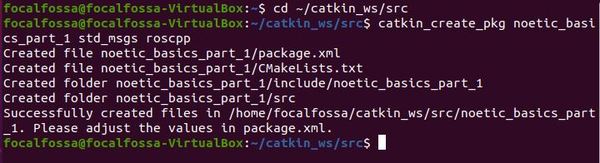
cd ~/catkin_ws/src
Now create the package.
catkin_create_pkg noetic_basics_part_1 std_msgs roscpp
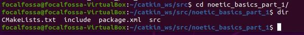
If you go inside the package, you’ll see we have all the basic files of a ROS package.
- CMakeLists.txt (contains the commands to build the ROS source code inside the noetic_basics_part_1 package)
- include (where the package header files are located)
- package.xml (contains descriptive information about the package)
- src (the folder that will contain your C++ source code…note that if you write Python code, you’ll want to create another folder inside the package named scripts).