In this tutorial, I will show you how to create a simulated mobile robot using the Universal Robot Description Format (URDF), the standard ROS format for robot modeling. This tutorial is the first tutorial in my Ultimate Guide to the ROS 2 Navigation Stack (also known as Nav2). Here is what you will create:

Roboticists like to simulate robots before building them in order to test out different algorithms. You can imagine the cost of making mistakes with a physical robot can be high (e.g. crashing a mobile robot into a wall at high speed means lost money).
You can get the entire code for this project here.
Let’s get started!
Prerequisites
- ROS 2 Foxy Fitzroy installed on Ubuntu Linux 20.04
- If you are using another ROS 2 distribution, you will need to replace ‘foxy’ with the name of your distribution everywhere I mention ‘foxy’ in this tutorial.
- I highly recommend you get the newest version of ROS 2. If you are using a newer version of ROS 2, you can still follow all the steps in this tutorial. Everything will work just fine.
- You have already created a ROS 2 workspace. The name of our workspace is “dev_ws”, which stands for “development workspace.”
What is URDF?
A URDF (Universal Robot Description Format) file is an XML file that describes what a robot should look like in real life. It contains the complete physical description of the robot. Building the body of the robot is the first step when getting started with Nav2.
The body of a robot consists of two components:
- Links
- Joints
Links are the rigid pieces of a robot. They are the “bones”.
Links are connected to each other by joints. Joints are the pieces of the robot that move, enabling motion between connected links.
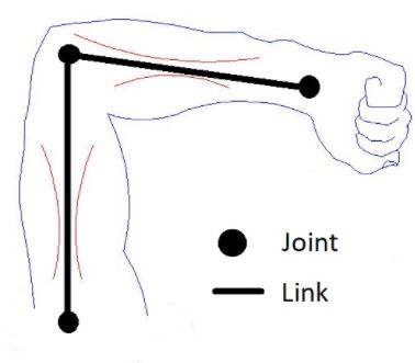
Consider the human arm below as an example. The shoulder, elbow, and wrist are joints. The upper arm, forearm and palm of the hand are links.
For a robotic arm, links and joints look like this.
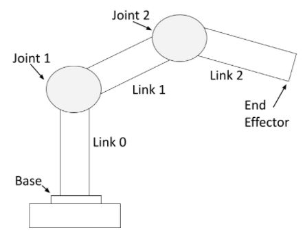
You can see that a robotic arm is made of rigid pieces (links) and non-rigid pieces (joints). Servo motors at the joints cause the links of a robotic arm to move.
For a mobile robot with LIDAR, links and joints look like this:
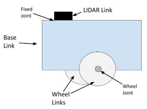
The wheel joints are revolute joints. Revolute joints cause rotational motion. The wheel joints in the photo connect the wheel link to the base link.
Fixed joints have no motion at all. You can see that the LIDAR is connected to the base of the robot via a fixed joint (i.e. this could be a simple screw that connects the LIDAR to the base of the robot).
You can also have prismatic joints. The SCARA robot in this post has a prismatic joint. Prismatic joints cause linear motion between links (as opposed to rotational motion).
Install the ROS 2 Navigation Stack (Nav2)
Now that you know what a URDF file is, let’s get to work.
Right now, I want you to complete this tutorial to install the ROS 2 Navigation Stack. Once you complete that tutorial, return to this page.
Don’t worry, setting up the ROS 2 Navigation Stack doesn’t take very long. Make sure to complete the entire tutorial before you come back here.
Install Important ROS 2 Packages
Now we need to install some important ROS 2 packages that we will use in this tutorial. Open a new terminal window, and type the following commands, one right after the other.
sudo apt install ros-foxy-joint-state-publisher-gui
sudo apt install ros-foxy-xacro
The format of the commands above is:
sudo apt install ros-<ros2-distro>-joint-state-publisher-gui
sudo apt install ros-<ros2-distro>-xacro
You will need to replace <ros2-distro> with the ROS 2 distribution you are using. In this case, I am using ROS 2 Foxy Fitzroy, which is ‘foxy’ for short.
Create a ROS 2 Package
Let’s create a ROS 2 package inside our workspace.
In a new terminal window, move to the src (source) folder of your workspace.
cd ~/dev_ws/src
Now create the package using the following command.
ros2 pkg create --build-type ament_cmake basic_mobile_robot
Create Extra Folders
Move inside the package.
cd ~/dev_ws/src/basic_mobile_robot
Create some extra folders with the following names.
mkdir config launch maps meshes models params rviz worlds
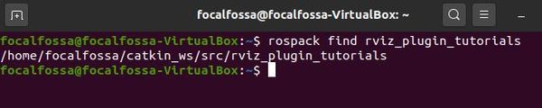
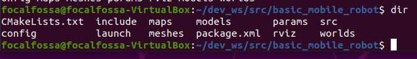
Type the following command to verify the folders were created.
dir
Now build the package by typing the following command:
cd ~/dev_ws
colcon build
Let’s add a script to our bashrc file which enables us to use the following command to move to the package from any directory inside our terminal window.
colcon_cd basic_mobile_robot
Where ‘cd’ means “change directory”.
Note that in ROS 1, we typed roscd to change directories. In ROS 2, we use the colcon_cd command instead of roscd.
Open a terminal window, and type the following commands, one right after the other:
echo "source /usr/share/colcon_cd/function/colcon_cd.sh" >> ~/.bashrc
echo "export _colcon_cd_root=~/dev_ws" >> ~/.bashrc
Now open a new terminal window.
To go directly to the basic_mobile_robot ROS 2 package, type:
colcon_cd basic_mobile_robot
This command above will get you straight to the basic_mobile_robot package from within any directory in your Linux system. The format is:
colcon_cd [ROS 2 package name]
Create the URDF File
In this section, we will build our mobile robot step-by-step. Our robot will be defined in a Universal Robot Descriptor File (URDF), the XML file that represents a robot model.
Open a new terminal window, and type:
colcon_cd basic_mobile_robot
cd models
Make sure you have the Gedit text editor installed.
sudo apt-get install gedit
Create a new file named basic_mobile_bot_v1.urdf.
gedit basic_mobile_bot_v1.urdf
Inside this file, we define what our robot will look like (i.e. visual properties), how the robot will behave when it bumps into stuff (i.e. collision properties), and its mass (i.e. inertial properties).
Type this code inside the URDF file.
Save and close the file.
All robots are made up of links and joints. If you go through the URDF file, you will see that we have defined each link and each joint of our two-wheeled robot.
The links of the mobile robot include the robot base (often called “chassis”), the two drive wheels, the front caster wheel, the IMU, and the GPS. We also have a virtual link known as the base footprint. The base footprint (as shown on this post) is the link directly under the center of the robot.
Each link of the robot is connected by a joint. The only two joints that move are the revolute joints for the left and right wheels that rotate, causing the wheel links to turn.
I use xacro in this file, which stands for XML macro language. Xacro helps avoid clutter in the URDF file by enabling us to define string constants that we can reuse throughout the URDF file (e.g. “wheel_radius”).
To learn more about URDF files, check out the official documentation.
Now go to the meshes folder.
cd ~/dev_ws/src/basic_mobile_robot/meshes
Add the following STL files to your meshes folder. A mesh is a file that allows your robot to look more realistic (rather than just using basic shapes like boxes and spheres).
Rather than use the STL files I provided, you can use a program like SolidWorks to generate your own STL files. You can also use a program called Blender to create DAE files. URDF files support meshes in either STL or DAE format.
Add Dependencies
Let’s add some packages that our project will depend on. Go to the package.xml file.
cd ~/dev_ws/src/basic_mobile_robot
gedit package.xml
After the <buildtool_depend> tag, add the following lines:
<exec_depend>joint_state_publisher</exec_depend>
<exec_depend>robot_state_publisher</exec_depend>
<exec_depend>rviz</exec_depend>
<exec_depend>xacro</exec_depend>
Save the file, and close it.
We will be using the Joint State Publisher and the Robot State Publisher. We will also be using RViz to visualize our robot model.
Create the Launch File
Let’s create a launch file. This launch file will be used by ROS 2 to load the necessary nodes for our package.
colcon_cd basic_mobile_robot
cd launch
cd ~/dev_ws/src/basic_mobile_robot/launch/
gedit basic_mobile_bot_v1.launch.py
Copy and paste this code into the file.
Save the file, and close it.
If you go through the launch file, you will see that we first set the path to the important files and folders our robot needs in order to launch properly.
After we set the paths to the files and folders, we set our LaunchConfiguration variables. You can think of these variables as our options for how we want to launch our robot simulation.
For example, imagine we want to launch our robot using the ROS 2 launch file, but we want to make sure that RViz (the robot visualization tool provided by ROS) remains turned OFF. We can create a flag called ‘use_rviz’. When we set ‘use_rviz’ to True, RViz launches, and when we set it to False, RViz does not launch.
In order for us to be able to set the value of this flag from a terminal window (i.e. outside the launch file), we have to do two things:
- Turn the string ‘use_rviz’ into a LaunchConfiguration variable since we can’t assign boolean values like True and False to a string like ‘use_rviz’. By using the LaunchConfiguration command, use_rviz == ‘use_rviz’.
- We also need to set the default value for this flag so that our system knows what to do if we don’t set its value from a terminal window as an argument when we launch our launch file. The DeclareLaunchArgument command sets the default value of the string ‘use_rviz’, which is True in the case of our launch file…and therefore, the LaunchConfiguration variable use_rviz also has a default value of True.
After we set and declare our launch arguments, we launch our ROS 2 nodes (e.g. the robot state publisher, RViz, etc.)
Add the RViz Configuration File
Let’s add a configuration file that will initialize RViz with the proper settings so we can view the robot as soon as RViz launches.
Open a new terminal window. Type:
colcon_cd basic_mobile_robot
cd rviz
gedit urdf_config.rviz
Add this code.
Save the file, and close it.
Build the Package
Now we need to build the package. Open a new terminal window, and type:
cd ~/dev_ws/src/basic_mobile_robot/
gedit CMakeLists.txt
Add the following snippet to CMakeLists.txt file above the if(BUILD_TESTING) line.
install(
  DIRECTORY config launch maps meshes models params rviz src worlds
  DESTINATION share/${PROJECT_NAME}
)
Save the file and close it.
Build the project.
cd ~/dev_ws/
colcon build
In the future, if you would like to build the basic_mobile_robot package only, you can type:
colcon build --packages-select basic_mobile_robot
Launch the Robot in RViz
Open a new terminal, and launch the robot.
cd ~/dev_ws/
ros2 launch basic_mobile_robot basic_mobile_bot_v1.launch.py
——
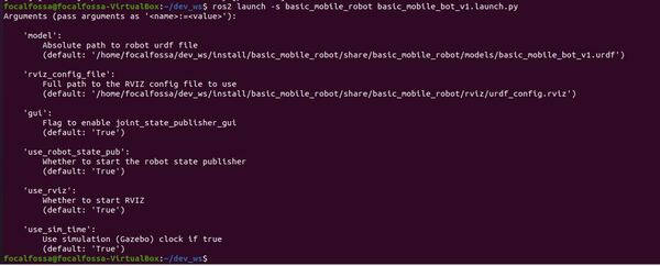
By the way, if you want to see the available arguments you can pass to the launch file from the terminal window, type:
ros2 launch -s basic_mobile_robot basic_mobile_bot_v1.launch.py
And if you want to set the value of an argument (e.g. launch the robot without RViz), you can do something like this (this is a single command):
ros2 launch basic_mobile_robot basic_mobile_bot_v1.launch.py use_rviz:='False'
——
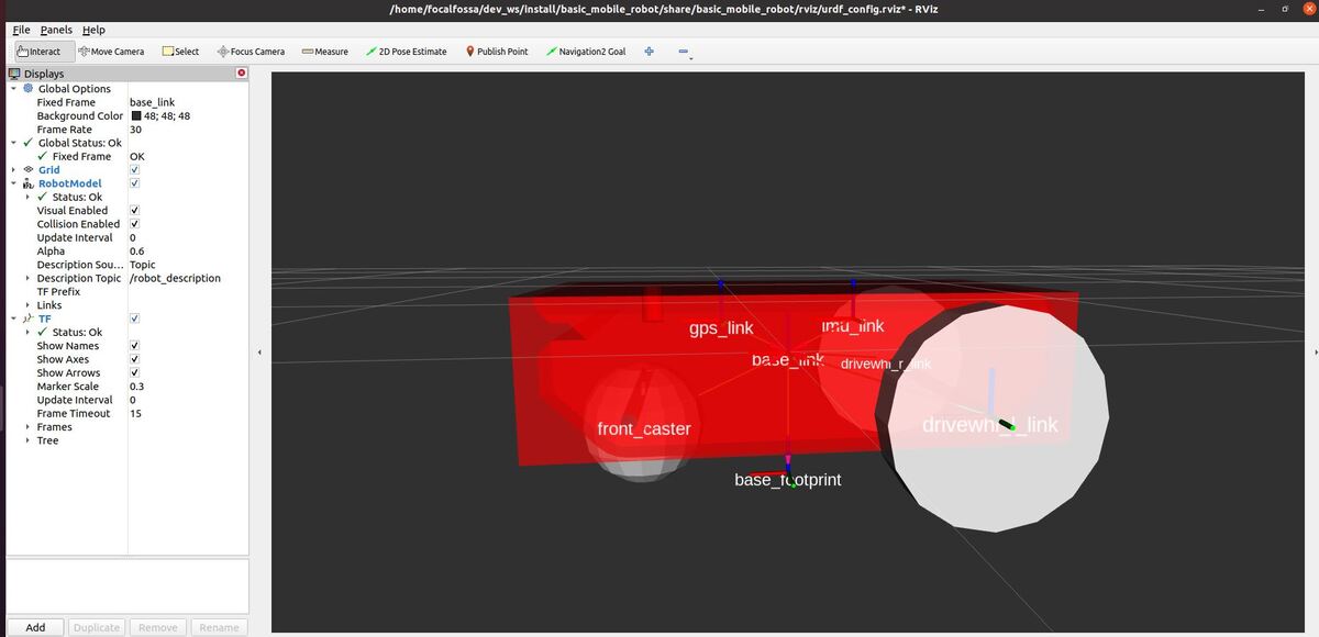
Here is the output after we launch the robot in RViz:
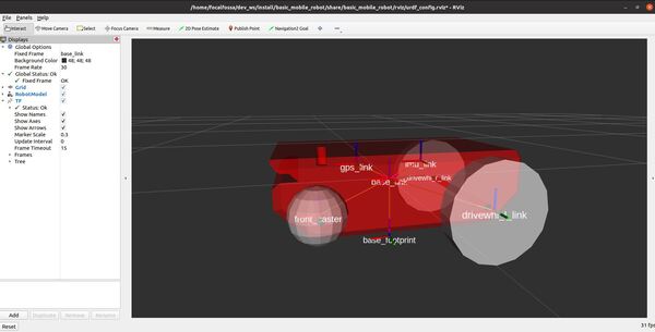
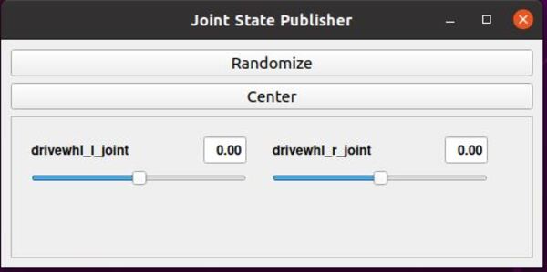
The joint state publisher GUI has sliders that enable you to move the wheels.
If something goes wrong with the launch, close everything down, restart Linux, and launch again.
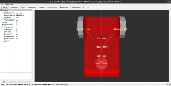
Check whether you have properly set up the collision properties by enabling Collision Enabled under RobotModel on the left pane.
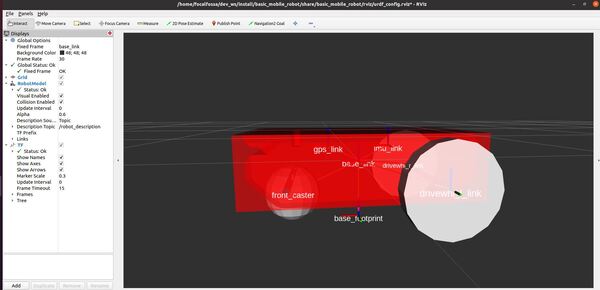
You can see in the image that I have modeled the base_link as a box for collisions. I could have just as easily used the STL model itself (which was used for visualization) as the collision geometry, but I decided to go with the simpler box representation to give me more flexibility to alter the collision areas if necessary. Also, Gazebo (a popular robotics simulator) recommends using simpler collision geometry to increase performance.
View the Coordinate Frames
Let’s see the coordinate frames. We first need to install the necessary software.
sudo apt install ros-foxy-tf2-tools
Again, if you have a different distribution of ROS 2, you will need to repalace ‘foxy’ in the command above with the name of your distribution.
Check out the coordinate frames.
ros2 run tf2_tools view_frames.py
In the current working directory, you will have a file called frames.pdf. Open that file.
evince frames.pdf
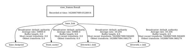
Here is what my coordinate transform (i.e. tf) tree looks like:
If we want to see the coordinate transformation from one link to another, we can type the following command. For example, what is the position and orientation of the front caster wheel relative to the base_link of the robot?
The syntax is:
ros2 run tf2_ros tf2_echo <parent frame> <child frame>
We open a terminal window, and type:
ros2 run tf2_ros tf2_echo base_link front_caster
Here is the output. With respect to the base_link reference frame, the front caster wheel is located at (x=0.217 meters, y=0 meters, and z=-0.1 meters).
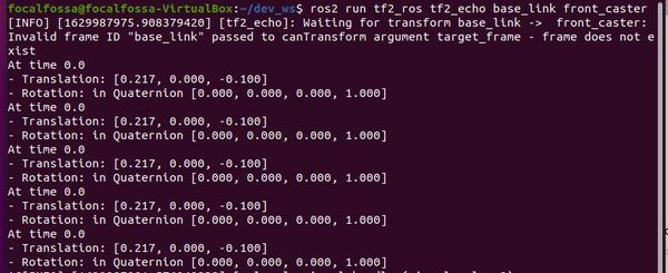
The rotation value is in quaternion format. You can see that the rotation values are all 0s, indicating that the orientation of both coordinate frames is equivalent (i.e. the x, y, and z axes of both coordinate frames point in the same direction).
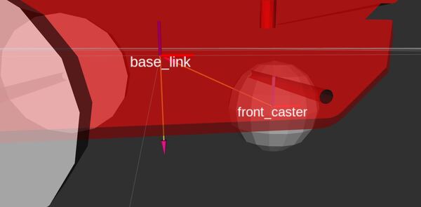
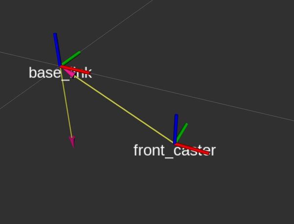
Remember that, by convention:
- x-axis is red
- y-axis is green
- z-axis is blue
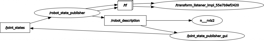
To see an image of the architecture of our ROS system, open a new terminal window, and type the following command:
rqt_graph
Select the “Nodes/Topics (all)” option in the upper-left part of the screen, and then click the refresh arrow right next to it.
You can see how the joint state publisher GUI manipulates the joint states (i.e. the angle of each wheel joint). This data feeds into the robot state publisher. The robot state publisher publishes the coordinate frame relationships to tf, and the updated robot model feeds into RViz, the robot model visualization program.
That’s it!
When you’re done, press CTRL+C in all terminal windows to shut everything down.
In the next tutorial, we will set up the odometry for our robot so that we can make the robot move and answer questions like “where is my robot located as it moves around in the world?”. Stay tuned!