In this tutorial, we’ll learn how to use ROS pluginlib.
What is ROS pluginlib?
Over the course of your work with ROS, there may be some situations where you want an application to have added functionality. However, you want that functionality to remain independent from the main application so that you can “plug it in” when you need it and unplug it when you don’t need it.
In short, the job of a plugin is to add some specific feature to an existing program.
The ROS pluginlib is a C++ library that enables you to load and unload plugins from within a package in ROS, giving your robot added capabilities.
ROS services are all about request/reply communication. A Service Client node sends a request (typically for some data) to a Service Server node. The Service Server node then replies to that request.
However, there may be some situations when the Service Client wants to cancel a request. This situation could occur when it is taking too long to receive a reply from the Service Server.
There are also some situations when the Service Client wants to get regular updates on the processing status of the request.
Fortunately, ROS has a solution for this. It is called the ROS’s actionlib package. The ROS actionlib package enables cancellation of requests and periodic feedback on the status of requests.
What is the Difference Between a ROS Service and a ROS Action?
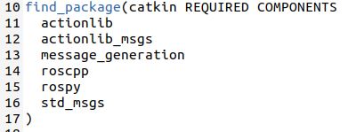
Here is an analogy to understand the difference between ROS Services and ROS Actions.
Let’s say you’re hungry. You order Chinese food from your local Chinese restaurant. Here are two ways communication might work during the ordering process between you (the client) and the restaurant (the server).
Option 1: Go to the Chinese Restaurant to Order Takeout
Place your order.
Wait for your order.
Receive your order.
Option 2: Order Chinese Food via an App on Your Smartphone (for Delivery)
Place your order.
Receive an order confirmation.
Consider cancelling your order.
Receive periodic updates on the status of your order.
Do some household tasks while you wait for your order.
Chinese food is delivered.
A ROS Service is like Option 1. It is a synchronous form of communication. After the client sends a request to a server, the client has to wait for a response from the server in order to continue doing other things.
Synchronous communication is also like talking on the telephone. When you’re talking on the telephone, you’re not free to do other things. You have to wait for the call to end to resume doing other things.
A ROS Action is like Option 2. It is an asynchronous form of communication. The client is free to do other things while it is waiting for a response from the server.
Asynchronous communication is like communicating via text message or e-mail. You send a request and then wait for a reply. In the meantime, you can do other things besides waiting for a response.
Here’s how ROS actions work. An ActionClient sends a request (i.e. a Goal) to an ActionServer. The goal might be, for example, for the robot to move to a particular location in the environment.
The ActionServer gives the ActionClient feedback on the progress it is making towards the execution of that goal (e.g. the robot’s most recent position along the path towards the goal location).
When the ActionServer completes the goal, it sends a result message to the ActionClient.
How to Create an ActionServer
Let’s create an ActionServer. The ActionServer’s job is to generate a Fibonacci sequence of a certain order (i.e.length). Don’t be scared if you’ve never heard of Fibonacci before.
A Fibonacci sequence is just a series of numbers in which the next number is found by adding up the two numbers before it, starting from 0 and 1. For example, here is a Fibonacci sequence:
0, 1, 1, 2, 3, 5, 8, 13, 21, 34, …
Notice that after 0 and 1, each number is the sum of the two numbers before it.
1 + 2 = 3 … 2 + 3 = 5, 3 + 5 = 8, etc.
A Fibonacci sequence of order 5, means the first 5 numbers of the sequence after the two seed numbers, which are 0 and 1:
0, 1, 1, 2, 3, 5, 8
In the next section of this tutorial, we will create an ActionClient. The ActionClient must send a goal to the ActionServer. The goal in this example will be the ActionClient’s desired order of the Fibonacci sequence (e.g. 5).
The ActionServer will take that order number as input (e.g. 5) and then reply to the ActionClient with the result (e.g. 0, 1, 1, 2, 3, 5, 8).
While the ActionServer is busy generating the requested Fibonacci sequence, it will send feedback to the ActionClient on its progress towards completing the goal.
Open up a new terminal window.
Move to the src folder of your workspace.
cd ~/catkin_ws/src
Create a package named actionlib_basics. Everything below is a single command that you type on one line in the terminal.
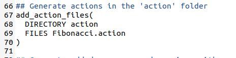
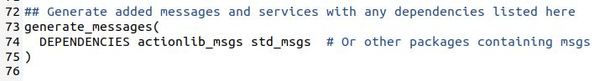
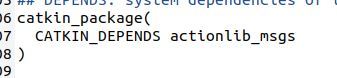
Now, let’s create an action. In this action, we’ll define the goal, result, and feedback messages. Create a new folder named action inside the actionlib_basics package.
Now, let’s generate the msg files out of the action files. Type the following commands in your terminal.
cd ~/catkin_ws/
catkin_make
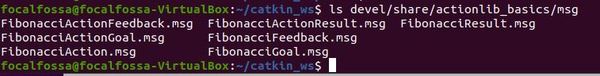
Now let’s see all the messages that were created.
ls devel/share/actionlib_basics/msg/
You should see 7 files in there.
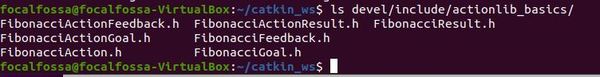
Let’s take a look at the header files.
ls devel/include/actionlib_basics/
Now that we’ve set up the message types, let’s create a program for the ActionServer.
Move to the src folder of the package.
roscd actionlib_basics/src
Create a new C++ program called fibonacci_server.cpp.
Type the following code inside it.
#include <ros/ros.h>
#include <actionlib/server/simple_action_server.h>
#include <actionlib_basics/FibonacciAction.h>

class FibonacciAction
{
protected:

  ros::NodeHandle nh_;
  actionlib::SimpleActionServer<actionlib_basics::FibonacciAction> as_; // NodeHandle instance must be created before this line. Otherwise strange error occurs.
  std::string action_name_;
  // create messages that are used to published feedback/result
  actionlib_basics::FibonacciFeedback feedback_;
  actionlib_basics::FibonacciResult result_;

public:

  FibonacciAction(std::string name) :
    as_(nh_, name, boost::bind(&FibonacciAction::executeCB, this, _1), false),
    action_name_(name)
  {
    as_.start();
  }

  ~FibonacciAction(void)
  {
  }

  void executeCB(const actionlib_basics::FibonacciGoalConstPtr &goal)
  {
    // helper variables
    ros::Rate r(1);
    bool success = true;

    // push_back the seeds for the fibonacci sequence
    feedback_.sequence.clear();
    feedback_.sequence.push_back(0);
    feedback_.sequence.push_back(1);

    // publish info to the console for the user
    ROS_INFO("%s: Executing, creating fibonacci sequence of order %i with seeds %i, %i", action_name_.c_str(), goal->order, feedback_.sequence[0], feedback_.sequence[1]);

    // start executing the action
    for(int i=1; i<=goal->order; i++)
    {
      // check that preempt has not been requested by the client
      if (as_.isPreemptRequested() || !ros::ok())
      {
        ROS_INFO("%s: Preempted", action_name_.c_str());
        // set the action state to preempted
        as_.setPreempted();
        success = false;
        break;
      }
      feedback_.sequence.push_back(feedback_.sequence[i] + feedback_.sequence[i-1]);
      // publish the feedback
      as_.publishFeedback(feedback_);
      // this sleep is not necessary, the sequence is computed at 1 Hz for demonstration purposes
      r.sleep();
    }

    if(success)
    {
      result_.sequence = feedback_.sequence;
      ROS_INFO("%s: Succeeded", action_name_.c_str());
      // set the action state to succeeded
      as_.setSucceeded(result_);
    }
  }


};


int main(int argc, char** argv)
{
  ros::init(argc, argv, "fibonacci");

  FibonacciAction fibonacci("fibonacci");
  ros::spin();

  return 0;
}
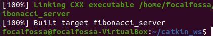
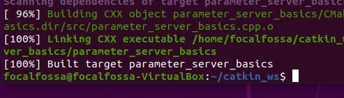
Now, let’s build everything again using the usual process.
cd ~/catkin_ws/
catkin_make
If it builds successfully, you should see this message in the terminal window.
Now let’s run the server.
In a fresh terminal window, type the following:
roscore
Open a new terminal tab, and type this command:
rosrun actionlib_basics fibonacci_server
You shouldn’t see any output. The ActionServer (i.e. fibonacci_server) is patiently waiting to receive a goal to execute.
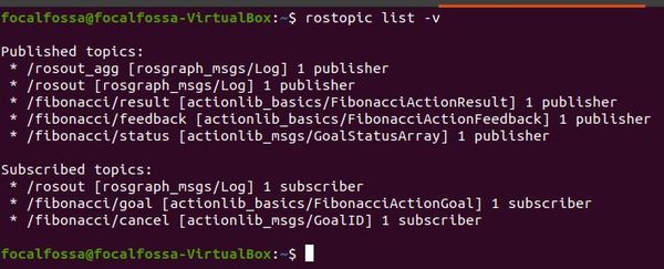
Let’s check to see if the actions are running properly by listing the current topics.
rostopic list -v
Press CTRL+C on all terminal windows to shutdown ROS.
That’s it. Now let’s create an ActionClient that can send the ActionServer (that we just created) some goals.
How to Create an ActionClient
Here is the official tutorial for creating an ActionClient, but I’ll run through the process below.
Move to the src folder of the package.
roscd actionlib_basics/src
Create a new C++ program called fibonacci_client.cpp.
Type the following code inside it.
#include <ros/ros.h>
#include <actionlib/client/simple_action_client.h>
#include <actionlib/client/terminal_state.h>
#include <actionlib_basics/FibonacciAction.h>

int main (int argc, char **argv)
{
  ros::init(argc, argv, "test_fibonacci");

  // create the action client
  // true causes the client to spin its own thread
  actionlib::SimpleActionClient<actionlib_basics::FibonacciAction> ac("fibonacci", true);

  ROS_INFO("Waiting for action server to start.");
  // wait for the action server to start
  ac.waitForServer(); //will wait for infinite time

  ROS_INFO("Action server started, sending goal.");
  // send a goal to the action
  actionlib_basics::FibonacciGoal goal;
  goal.order = 20;
  ac.sendGoal(goal);

  //wait for the action to return
  bool finished_before_timeout = ac.waitForResult(ros::Duration(30.0));

  if (finished_before_timeout)
  {
    actionlib::SimpleClientGoalState state = ac.getState();
    ROS_INFO("Action finished: %s",state.toString().c_str());
  }
  else
    ROS_INFO("Action did not finish before the time out.");

  //exit
  return 0;
}
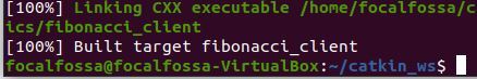
Now, let’s build everything again using the usual process.
cd ~/catkin_ws/
catkin_make
If it builds successfully, you should see this message in the terminal window.
Now let’s run the client.
In a fresh terminal window, type the following:
roscore
Open a new terminal tab, and type this command:
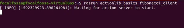
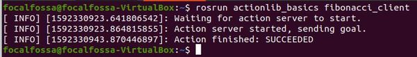
rosrun actionlib_basics fibonacci_client
You should see a message that says “Waiting for action server to start.” Going back to our Chinese restaurant analogy, the customer is waiting for the restaurant to open.
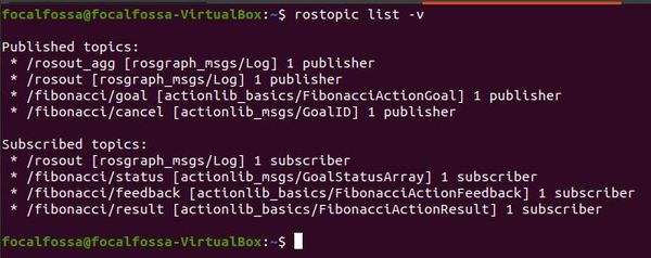
Let’s check to see the current topics. In a new terminal window, type:
rostopic list -v
Press CTRL+C on all terminal windows to shutdown ROS.
That’s it. Now let’s see how to run both the ActionClient and ActionServer at the same time.
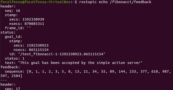
Let’s see the feedback from the ActionServer while it is in the middle of executing the goal. In a new tab, type:
rostopic echo /fibonacci/feedback
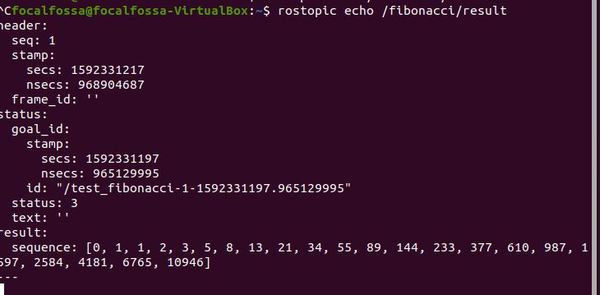
Let’s check out the action result. In a new terminal tab, type:
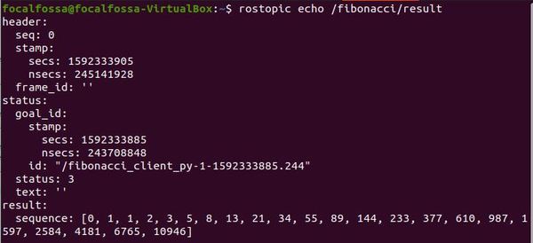
rostopic echo /fibonacci/result
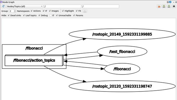
To see the communication lines between the ActionServer and ActionClient, in a new terminal tab, type:
rqt_graph
If you didn’t get the same output, try again, typing in the commands above quickly. It doesn’t take long (~10 seconds on my computer) for the ActionServer to execute the goal in this case (i.e. creating a Fibonacci sequence of order 20).
In a real robotics project, you won’t need to type in all the commands so fast because your robot will most likely be operating for longer than 10 seconds.
When you’re done, type CTRL+C on the window where you launched the ROS Master (i.e. roscore).
Create a new Python program called fibonacci_client.py.
gedit fibonacci_client.py
Type the following code inside it.
#! /usr/bin/env python3
from __future__ import print_function
import rospy


# Brings in the SimpleActionClient
import actionlib

# Brings in the messages used by the fibonacci action, including the
# goal message and the result message.
import actionlib_basics.msg

def fibonacci_client():
    # Creates the SimpleActionClient, passing the type of the action
    # (FibonacciAction) to the constructor.
    client = actionlib.SimpleActionClient('fibonacci', actionlib_basics.msg.FibonacciAction)

    # Waits until the action server has started up and started
    # listening for goals.
    client.wait_for_server()

    # Creates a goal to send to the action server.
    goal = actionlib_basics.msg.FibonacciGoal(order=20)

    # Sends the goal to the action server.
    client.send_goal(goal)

    # Waits for the server to finish performing the action.
    client.wait_for_result()

    # Prints out the result of executing the action
    return client.get_result()  # A FibonacciResult

if __name__ == '__main__':
    try:
        # Initializes a rospy node so that the SimpleActionClient can
        # publish and subscribe over ROS.
        rospy.init_node('fibonacci_client_py')
        result = fibonacci_client()
        print("Result:", ', '.join([str(n) for n in result.sequence]))
    except rospy.ROSInterruptException:
        print("program interrupted before completion", file=sys.stderr)
Click Save.
Close the editor.
Make the file executable.
chmod +x fibonacci_client.py
Now type the following commands to build the node:
cd ~/catkin_ws
catkin_make
Now let’s run our ActionServer (created using C++) and our ActionClient (create using Python).
In a new terminal window, launch ROS.
roscore
In a new terminal tab, type:
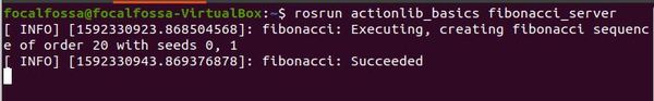
rosrun actionlib_basics fibonacci_server
In another terminal tab, type:
rosrun actionlib_basics fibonacci_client.py
Let’s see the feedback from the ActionServer while it is in the middle of executing the goal. In a new tab, type:
rostopic echo /fibonacci/feedback
Let’s check out the action result. In a new terminal tab, type:
rostopic echo /fibonacci/result
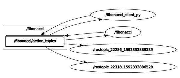
To see the communication lines between the ActionServer and ActionClient, in a new terminal tab, type:
rqt_graph
Here is the node graph:
Here is the output of the /fibonacci/result tab we opened up.
To run the client again, go back to the terminal where you ran fibonacci_client.py, and type the up arrow on your keyboard. Then press Enter to run this command again:
rosrun actionlib_basics fibonacci_client.py
When you’re done, press CTRL+C to close down everything.
Parameters are globally available values such as integers, floats, strings or booleans. Any node in ROS can access and modify these values. You should use parameters for data that you do not expect to change a lot over time.
Nodes (i.e. programs in C++/Python that exist inside ROS packages), can use parameters during runtime.
Parameters are stored inside a centralized Parameter Server. The Parameter Server is like a dictionary that contains the name of the parameter and the corresponding value of the parameter.
The Parameter Server is part of the ROS Master, so it launches automatically when you launch either roscore or roslaunch.
To get a list of the currently active parameters on your system, open a new terminal window, and type:
roscore
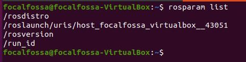
rosparam list
Here we see the name of the active parameters.
If you want to see the value of the parameter, you use this syntax:
rosparam get <name_of_parameter>
For example, type:
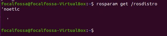
rosparam get /rosdistro
We see that the value of the /rosdistro (i.e. “ROS distribution”) is noetic, which is exactly what we would expect.
If you want to see the values of all parameters at once, you type this command:
rosparam get /
To assign a value to a parameter, you use this command.
rosparam set <name_of_parameter> <desired_value>
Followed by this command to complete the update of the parameter value.
rosservice call /clear
How to Update Parameters Using the dynamic_reconfigure Package
Imagine we have two nodes written in either Python or C++. One node sets the value of a particular parameter on the Parameter Server. The other node uses the value of that parameter to perform some computation. This latter node typically reads the value of the parameter only when the node is first launched. How will this latter node know if the value of the parameter has changed during runtime?
Fortunately, ROS has an efficient solution for this. To update the value of a parameter dynamically (i.e. “on-the-fly”) while a node is running, we can use the dynamic_reconfigure package. This package enables us to update parameters on the Parameter Server at runtime and push that change out to a given active node that needs the most current value of that parameter.
This is cool because it means we don’t have to restart a node in order for it to recognize the change in the value of a parameter.
A common use case for the dynamic_reconfigure package is when you’ve built a control system that needs to precisely control the speed of a motor. You might need to continuously tune the control parameters to make the robot move how you want it to move. Doing so requires continuous updates. The dynamic_reconfigure package provides an efficient means of doing this.
Create a cfg directory. This is where all the cfg files will be.
mkdir cfg
Move inside the cfg directory you just created.
cd cfg
Now let’s create a file named parameter_server_basics.cfg.
gedit parameter_server_basics.cfg
Write the following code:
#!/usr/bin/env python3

PACKAGE = "parameter_server_basics"

from dynamic_reconfigure.parameter_generator_catkin import *

gen = ParameterGenerator()

gen.add("int_param",    int_t,    0, "An Integer parameter", 50,  0, 100)
gen.add("double_param", double_t, 0, "A double parameter",    .5, 0,   1)
gen.add("str_param",    str_t,    0, "A string parameter",  "Hello World")
gen.add("bool_param",   bool_t,   0, "A Boolean parameter",  True)

size_enum = gen.enum([ gen.const("Small",      int_t, 0, "A small constant"),
                       gen.const("Medium",     int_t, 1, "A medium constant"),
                       gen.const("Large",      int_t, 2, "A large constant"),
                       gen.const("ExtraLarge", int_t, 3, "An extra large constant")],
                     "An enum to set size")

gen.add("size", int_t, 0, "A size parameter which is edited via an enum", 1, 0, 3, edit_method=size_enum)

exit(gen.generate(PACKAGE, "parameter_server_basics", "parameter_server_"))
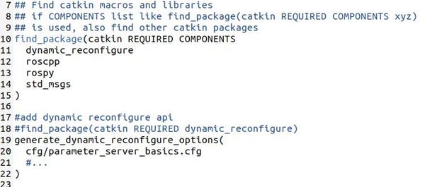
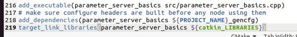
Let’s edit the CMakeLists.txt file for the parameter_server_basics package.
Open a new terminal window, and type this command:
roscd parameter_server_basics
gedit CMakeLists.txt
Now add these lines to the bottom of the CMakeLists.txt file. Make sure the add_dependencies line you added in the last section is between add_executable… and target_link_libraries:
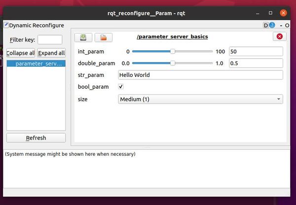
Click on parameter_server_basics on the left-hand side.
Here is what you should see:
To modify the parameters, drag any of the sliders. You can also uncheck the boolean checkbox there.
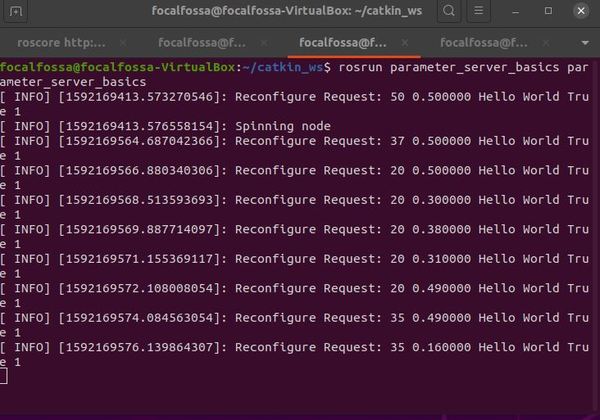
Each time you make a change to one of the parameters, you’ll see the change printed out to the terminal window where you ran rosrun parameter_server_basics parameter_server_basics.
When you’re finished, type Ctrl + C on all terminal windows to shutdown ROS.