In this tutorial, we are going to learn how to write loops in Python. Loops are a key tool for iterating over sequences and automating repetitive tasks.
Prerequisites
You have completed this tutorial: How to Use Python’s Most Common Data Structures.
Writing For Loops
Let’s create a new file named writing_for_loops.py inside the following folder: ~/Documents/python_tutorial.
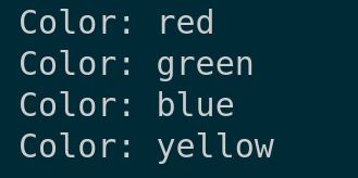
First, let’s demonstrate a simple for loop with a list of colors.
Type the following code into the editor:
# Simple for loop with a list
colors = ['red', 'green', 'blue', 'yellow']
for color in colors:
    print("Color:", color)
This loop prints each color in our list, showing how for loops process elements one by one.
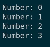
Next, we’ll use a for loop with the range() function, which generates a sequence of numbers.
# For loop with range
for i in range(4):  # Generates numbers from 0 to 3
    print("Number:", i)
Here, range(4) produces numbers from 0 to 3, and we print each one.
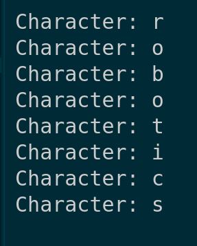
For loops can also iterate over strings, treating each character as an item.
# Iterating over a string
for char in 'robotics':
    print("Character:", char)
This prints each character in ‘robotics’.
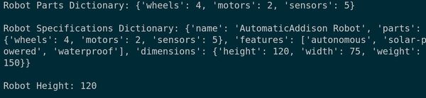
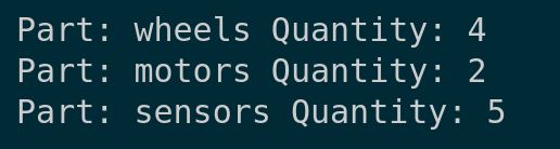
Next, let’s loop through a dictionary of robot parts.
# Looping through a dictionary
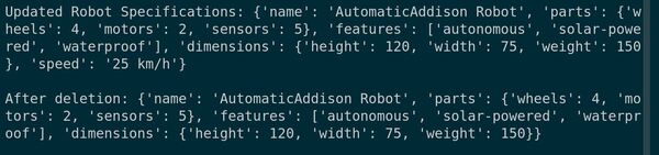
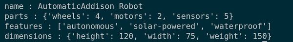
robot_parts = {'wheels': 4, 'motors': 2, 'sensors': 5}
for part, quantity in robot_parts.items():
print("Part:", part, "Quantity:", quantity)
Using .items() allows us to print both keys and values.
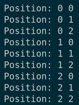
Lastly, we’ll explore nested for loops, useful for processing multi-dimensional data.
# Nested for loops
for outer in range(3):
    for inner in range(3):
        print("Position:", outer, inner)
This generates a grid of positions from (0, 0) to (2, 2).
Save your file, and let’s run it to see these for loops in action.
You can see how for loops effectively handle various data structures.
Writing While loops
Let’s explore how to effectively use while loops in Python. These loops are essential for executing code repeatedly based on a condition.
Open your code editor and start a new file, writing_while_loops.py inside the following folder: ~/Documents/python_tutorial.
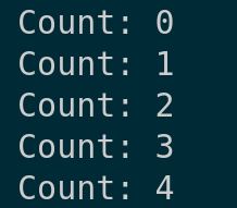
First, let’s look at a basic while loop that prints numbers from 0 to 4.
# Basic while loop
count = 0
while count < 5:
    print("Count:", count)
    count += 1
This loop increments ‘count’ each time, stopping when it reaches 5.
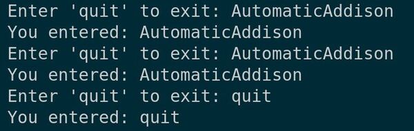
Next, we’ll use a while loop to handle user input. This loop will continue until ‘quit’ is entered.
# While loop with user input
user_input = ""
while user_input.lower() != 'quit':
    user_input = input("Enter 'quit' to exit: ")
    print("You entered:", user_input)
This demonstrates a loop that runs based on user interaction.
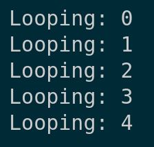
Finally, let’s use the ‘break’ statement to exit a loop prematurely.
# Using break in a while loop
count = 0
while True:
    if count == 5:
        break
    print("Looping:", count)
    count += 1

print("")
This loop runs indefinitely but breaks when ‘count’ reaches 5.
Save your file, and then let’s run the script to see these while loops in action.
You’ll see how each while loop works, demonstrating their versatility and power in handling different types of data structures.
We’ve covered basic to advanced uses of while loops, showing how they control flow in programs. Thanks, and I’ll see you in the next tutorial.
Keep building!