I’ve written before about how to create a simple publisher node in ROS, but let’s review the process.
We’ll take a look at C++ nodes and Python nodes, although our main focus for this entire tutorial will be C++-based nodes.
The main difference when you create a Python node is that you’ll want to create a new directory named “scripts” (using the mkdir scripts command) inside your noetic_basics_part_1 package. C++ nodes go in the src folder, while Python nodes go inside the scripts folder. We’ll do all this together, step-by-step.
How to Create a Publisher Node in C++
So, what is a node in ROS? A node in ROS is just a program (e.g. typically a piece of source code made in C++ or Python) that does some computation. ROS nodes reside inside ROS packages. ROS packages reside inside the src folder of your catkin workspace (i.e. catkin_ws).
One of the best definitions of a ROS node comes from Jason O’Kane’s book, A Gentle Introduction to ROS:
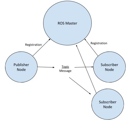
“One of the basic goals of ROS is to enable roboticists to design software as a collection of small ,mostly independent programs called nodes that all run at the same time. For this to work, those nodes must be able to communicate with one another. The part of ROS that facilitates this communication is called the ROS master.”
A publisher node is a program that publishes data (e.g. a sensor reading on a robot). A subscriber node is a program that subscribes to published data. Nodes communicate with each other by passing messages (i.e. publishing data and subscribing to that data) via named topics. You can also have nodes that both publish data and subscribe to data.
The entity that manages the whole communication process between nodes is called the ROS Master.
Also note that you can have mixed nodes as well, which are nodes that are both subscribers and publishers.
The command for starting the ROS Master is (no need to run this code at this stage):
roscore
Whenever you use ROS to execute your robotics programs, you need to make sure the ROS Master is running the entire time. You’ll only stop the ROS Master (using Ctrl + C on your keyboard) when you’re finished using ROS.
What I like to always do is open up a new terminal window, start the ROS Master using the roscore command, then open up another terminal window to do all the ROS-related work.
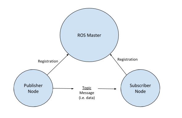
When you want to run a publisher and/or subscriber node, you have to make sure ROS Master is running because these nodes need to register with the ROS Master. ROS Master enables publisher nodes and subscriber nodes to pass data (i.e. messages) between each other via named topics.
A good analogy is YouTube. YouTubers (publisher nodes) publish videos (messages) to a channel (topic), and you (subscriber node) can subscribe to that channel (topic) so that you receive all the videos (messages) on that channel (topic). YouTube (ROS Master) keeps track of who is a publisher and who is a subscriber. One thing to keep in mind is that (in contrast to YouTube) in ROS there can be multiple publishers to the same topic, and publishers and subscribers don’t know each other.
Let’s create a simple publisher node in C++ that publishes the data “Hello Automatic Addison!” to a ROS topic named /message.
Open up a new terminal window.
Move to the src folder of the package we created earlier called noetic_basics_part_1.
roscd noetic_basics_part_1/src
Let’s create a C++ program named simple_publisher_node.cpp. The name for this node in ROS will be simple_publisher_node. The purpose of this node is to publish the message “Hello Automatic Addison!” to the topic named /message.
Remember that topics in ROS start with the “/” character.
Ok, now type this command to open a brand new C++ file.
gedit simple_publisher_node.cpp
Type the code below into the file, one line at a time so that you read all the comments and know what is going on. Creating a node in ROS that can publish data is one of the most fundamental things you’ll do when working with ROS.
/**
 * A basic program to publish messages to a ROS topic
 * @author Addison Sears-Collins (https://automaticaddison.com/)
 * @version 1.0
 */

// Include the header file that has declarations for the standard ROS classes
#include "ros/ros.h"

// Header file for messages of type std_msgs::String
// Each type of message you use in a program will have a C++ header file you
// need to include. The syntax is #include <package_name/type_name.h>
// Here we want to publish messages of type String that are owned by the
// std_msgs package (http://wiki.ros.org/std_msgs)
#include "std_msgs/String.h"

// The sstream library enables numeric values to be converted into Strings
#include <sstream>

/**
 * Main method
 */
int main(int argc, char **argv) {

  // Initialize the node and set the name.
  // The ros::init() function needs to see argc and argv.
  // The third argument is the name of the node.
  ros::init(argc, argv, "simple_publisher_node");

  // Create the main access point for the node
  // This piece of code enables the node to communicate with the ROS system.
  ros::NodeHandle n;

  // Create a Publisher object.
  // We use the advertise() function to tell the ROS Master the type of
  // messages (e.g. strings) we want to publish to the /message topic.
  // The second parameter to advertise() is the size of the message queue
  // used for publishing messages.  If our node is publishing messages
  // at a rate that is too fast for the ROS system to handle,
  // 1000 messages will be kept in the queue before deleting the oldest unsent
  // messages.
  // The syntax is ros::Publisher pub = node_handle.advertise<message_type>(
  //   topic_name, queue_size);
  // If you'd like to publish messages on more than one topic, you need to
  // create separate ros:Publisher object for each topic you publish too.
  ros::Publisher pub = n.advertise<std_msgs::String>("message", 1000);

  // Set a data (i.e. message) sending frequency of 10 Hz
  // (i.e. every 100ms...because 1/10 * 1000)
  // This rate controls how quickly the while loop below runs.
  ros::Rate loop_rate(10);

  // Keep track of how many messages we have sent.
  int count = 0;

  // Stop the node if either ROS stops all the nodes, or we press Ctrl + C on
  // our keyboard.
  while (ros::ok()) {

    // Create the message object. We will stuff data into msg and then
    // publish it.
    std_msgs::String msg;

    // Create a stringstream variable that will help us convert numerical data
    // into a string
    std::stringstream ss;

    // Read the string as well our running tally of how many strings
    // we have published thus far.
    ss << "Hello Automatic Addison! " << count;

    // Convert all that stuff stored into ss into a string and store
    // that in the data field of the msg object.
    msg.data = ss.str();

    // Display the message data to the terminal window. This is helpful for
    // debugging.
    ROS_INFO("%s", msg.data.c_str());

    // Publish the message. msg will get added to the outgoing message queue
    // and will go out to the topic as soon as possible so that subscribers can
    // see it.
    pub.publish(msg);

    // This code is optional since we don't have any subscribing going on in
    // this node. If this were a subscriber node, you would want this line of
    // code. When a subscriber node receives a message via a topic, it doesn't
    // process the message immediately. Instead, the message waits in a queue
    // until the spinOnce() function is called.
    ros::spinOnce();

    // Sleep for whatever time needed so we make sure we hit our target
    // publishing frequency of 1 message every 100ms (i.e. 10Hz or
    // 10 messages per second)
    loop_rate.sleep();

    // Increase the number of published messages by 1
    ++count;

  }

  // Code was executed successfully
  return 0;
}
In a nutshell, what we are doing above is:
- Initializing ROS
- Letting the ROS Master know that we will publish std_msgs/String (i.e. strings) type messages to the /message topic.
- Publish a new message to the /message topic every 100ms (i.e. 10 times per second).
How to Create a Publisher Node in Python
If you’re not interested in creating Python nodes, feel free to skip this section.
You might recall that when we created our noetic_basics_part_1 package, we added the following dependencies: std_msgs and roscpp.
To get Python nodes to run, you will need to add the rospy dependency. rospy is the Python client library for ROS. To add rospy to your noetic_basics_part_1 package, you would type the following commands:
roscd noetic_basics_part_1
gedit package.xml
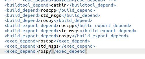
Add these three lines in the lines:
<build_depend>rospy</build_depend>
<build_export_depend>rospy</build_export_depend>
<exec_depend>rospy</exec_depend>
Click Save and close it.
Go to your package.
roscd noetic_basics_part_1
Create a scripts folder.
mkdir scripts
Go to the scripts folder.
cd scripts
Create a new Python publisher node.
gedit simple_python_publisher.py
Type the following code inside it:
#!/usr/bin/env python3
# license removed for brevity
import rospy
from std_msgs.msg import String

def publish_message():
    pub = rospy.Publisher('message_py', String, queue_size=10)
    rospy.init_node('simple_python_publisher', anonymous=True)
    rate = rospy.Rate(10) # 10hz
    while not rospy.is_shutdown():
        hello_str = "Hello Automatic Addison! %s" % rospy.get_time()
        rospy.loginfo(hello_str)
        pub.publish(hello_str)
        rate.sleep()

if __name__ == '__main__':
    try:
        publish_message()
    except rospy.ROSInterruptException:
        pass
For a full line-by-line explanation of the code above, check out this link at the ROS website.
Save the file and close it.