Let’s write a publisher and a subscriber node to use the custom message file we just created. I will borrow heavily from simple_publisher_node.cpp and simple_subscriber_node.cpp we made earlier in this tutorial.
We will create two files:
simple_publisher_node_custom_msgs.cpp and simple_subscriber_node_custom_msgs.cpp
To keep this code short, I will not use any comments. If you don’t understand something, take a look at the simple_publisher_node.cpp and simple_subscriber_node.cpp files from earlier in this tutorial.
Open up a new terminal window.
Move to the src folder of the package we created earlier called noetic_basics_part_1.
roscd noetic_basics_part_1/src
Let’s create a C++ program named simple_publisher_node_custom_msgs.cpp. The name for this node in ROS will be simple_publisher_node_custom_msgs.
Type this command to open a brand new C++ file.
gedit simple_publisher_node_custom_msgs.cpp
Type the code below into the file.
#include "ros/ros.h"
#include "noetic_basics_part_1/noetic_basics_part_1_msg.h"
#include <sstream>
int main(int argc, char **argv) {
ros::init(argc, argv, "simple_publisher_node_custom_msgs");
ros::NodeHandle n;
ros::Publisher pub = n.advertise<noetic_basics_part_1::noetic_basics_part_1_msg>("noetic_basics_part_1/message", 1000);
ros::Rate loop_rate(10);
while (ros::ok()) {
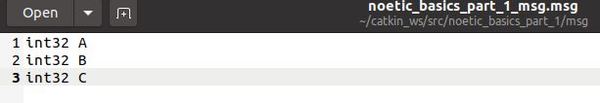
noetic_basics_part_1::noetic_basics_part_1_msg msg;
msg.A = 1;
msg.B = 2;
msg.C = 3;
pub.publish(msg);
ros::spinOnce();
loop_rate.sleep();
}
return 0;
}
Click Save and close the editor.
Now type this command to open a brand new C++ file.
gedit simple_subscriber_node_custom_msgs.cpp
#include "ros/ros.h"
#include "noetic_basics_part_1/noetic_basics_part_1_msg.h"

void messageCallback(const noetic_basics_part_1::noetic_basics_part_1_msg::ConstPtr& msg) {
  ROS_INFO("I have received: [%d] [%d] [%d]", msg->A, msg->B, msg->C);
}

int main(int argc, char **argv) {
  ros::init(argc, argv, "simple_subscriber_node_custom_msgs");
  ros::NodeHandle n;
  ros::Subscriber sub = n.subscribe("noetic_basics_part_1/message", 1000, messageCallback);
  ros::spin();
  return 0;
}
Click Save and close the editor.
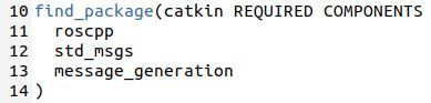
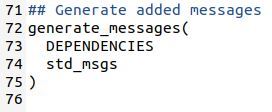
Let’s edit the CMakeLists.txt file for the noetic_basics_part_1 package. Open a new terminal window, and type this command:
roscd noetic_basics_part_1
gedit CMakeLists.txt
Now add these lines to the bottom of the CMakeLists.txt file:
add_executable(simple_publisher_node_custom_msgs src/simple_publisher_node_custom_msgs.cpp)
target_link_libraries(simple_publisher_node_custom_msgs ${catkin_LIBRARIES})

add_executable(simple_subscriber_node_custom_msgs src/simple_subscriber_node_custom_msgs.cpp)
target_link_libraries(simple_subscriber_node_custom_msgs ${catkin_LIBRARIES})
Click Save and close the text editor.
Open a new terminal window, and type the following commands to build all the nodes in the noetic_basics_part_1 package:
cd ~/catkin_ws
catkin_make
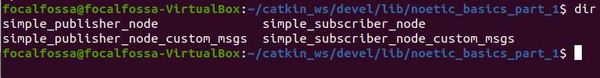
Now, open a new terminal window and go to the catkin_ws/devel/lib/noetic_basics_part_1/ folder.
cd ~/catkin_ws/devel/lib/noetic_basics_part_1/
Type dir to see the files listed. You will see the new executables we just created. Feel free to close the terminal window now.
Ok, now that we have built our nodes, let’s run them.
Open up a new terminal window and launch the ROS Master.
roscore
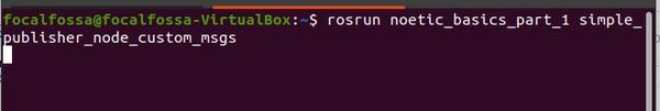
In a new terminal tab, type the following command to run the publisher node:
rosrun noetic_basics_part_1 simple_publisher_node_custom_msgs
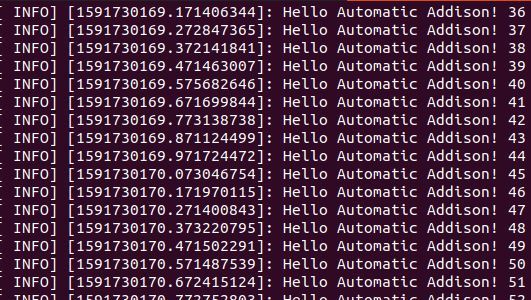
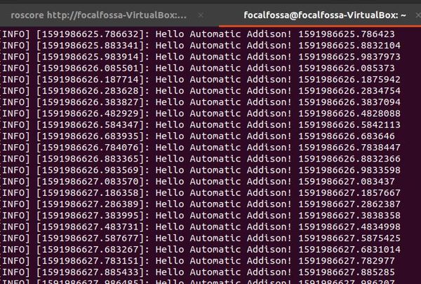
Here is the output. You shouldn’t see anything because we are not printing to the terminal window using the ROS_INFO command.
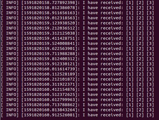
Now, let’s run the subscriber node. Type the following command in a new terminal tab.
rosrun noetic_basics_part_1 simple_subscriber_node_custom_msgs
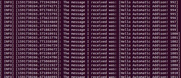
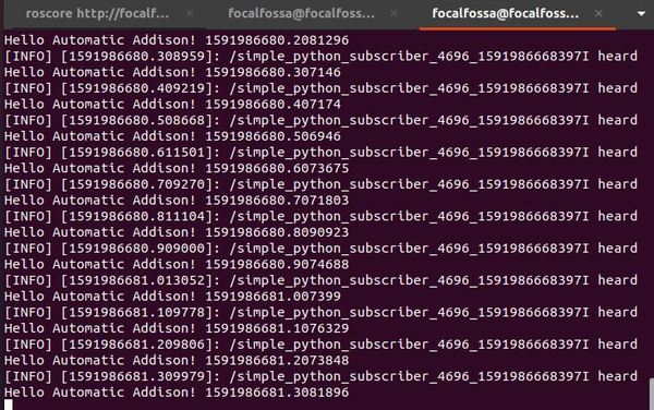
Here is the output:
When you’re done, press Ctrl + C in all open terminal windows.