In this tutorial, we will explore the various sensors commonly used in mobile robotics for navigation and mapping using Nav2.
Mobile robots rely on a wide array of sensors to perceive and understand their surroundings, enabling them to:
- Build accurate maps
- Localize themselves within those maps
- Detect obstacles for safe navigation through dynamic environments
If you prefer learning by video, watch the video below, which covers this entire tutorial from start to finish.
Prerequisites
- You have completed this tutorial: How to Install ROS 2 Navigation (Nav2) – ROS 2 Jazzy.
- You have completed this tutorial: Understanding Coordinate Transformations for Navigation.
All my code for this project is located here on GitHub.
Common Sensors
Some of the most frequently used sensors in mobile robotics include:
- Lidar
- IMUs
- Depth cameras
- RGB cameras
- GPS
The mobile robot I use for the examples in this tutorial is equipped with simulated LIDAR, IMU, and a depth camera.
An RGB camera is nice to have but not critical for navigation.
GPS is not relevant to use because our robot is designed for indoor navigation.
For a real robot, instead of using simulated sensors, we would use real hardware. Fortunately, most of the popular LIDARs, IMUs, and depth cameras on the market have ROS 2 publishers you can find on GitHub that will read the data from the sensor and publish that data in a ROS 2-compatible format. These ROS 2 publishers are also known as “drivers.”
How ROS 2 Helps Sensors Work Together
The beauty of ROS 2 is how it makes it easier for different types of sensors to work together, even if they’re made by different companies. It does this by providing special packages that define standard ways for sensors to communicate.
The sensor_msgs package creates a common language for a variety of sensors. This means that you can use any sensor as long as it speaks this common language.
Some of the most important messages for navigation include:
- sensor_msgs/LaserScan: Used for LIDARs
- sensor_msgs/PointCloud2: Used for depth cameras
- sensor_msgs/Range: Used for distance sensors, both infrared and ultrasonic sensors
- sensor_msgs/Image: Used for cameras
In addition to the sensor_msgs package, we have two other packages that you should know about if you come across these during your robotics career:
radar_msgs
The radar_msgs package is specifically for radar sensors and defines how they should communicate.
vision_msgs
The vision_msgs package is for sensors used in computer vision, like cameras that can detect and recognize objects or people. Some of the messages it supports include:
- vision_msgs/Classification2D and vision_msgs/Classification3D: Used for identifying objects in 2D or 3D
- vision_msgs/Detection2D and vision_msgs/Detection3D: Used for detecting objects in 2D or 3D
As mentioned earlier, most real robots come with special programs called ROS drivers that allow their sensors to talk using the common language defined in these packages. This makes it easier to use sensors from different manufacturers because general software packages like Nav2 can understand this common language and do their job no matter what specific sensor hardware is being used.
In simulated environments, like what we will use in this tutorial, special plugins, which we defined in the URDF file, are used to make the simulated sensors communicate using the sensor_msgs package format.
Visualizing Sensor Data in RViz
Let’s take a look at the sensor data we have to work with on our simulated robot. Open a terminal window, and type this command:
navor
bash ~/ros2_ws/src/yahboom_rosmaster/yahboom_rosmaster_bringup/scripts/rosmaster_x3_navigation.shIn the “Fixed Frame” field, enter odom as the Fixed Frame.
Let’s look at the sensor readings.
Click the “Add” button at the bottom of the RViz window.
Click the “By topic” tab.
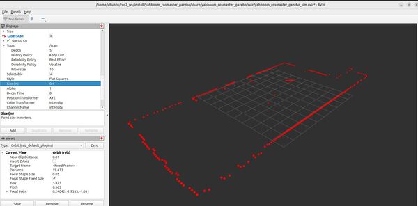
Select the “/scan” topic so we can view the sensor_msgs/LaserScan messages.
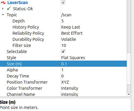
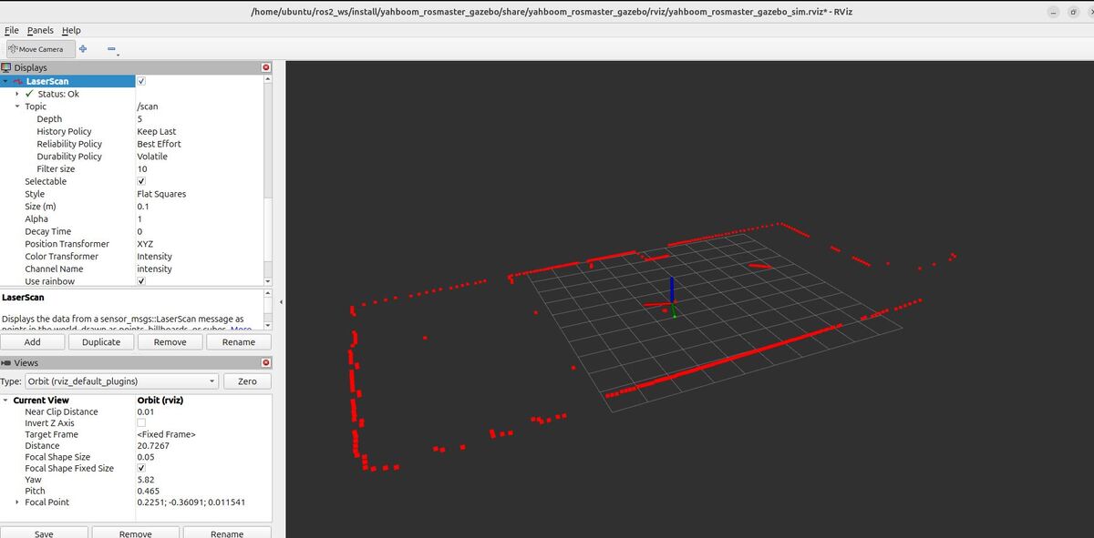
On the left panel, set the Reliability Policy in RViz to “Best Effort”. Setting the Reliability Policy to “Best Effort” for a LIDAR sensor means that RViz will display the most recently received data from the sensor, even if some data packets have been lost or delayed along the way.
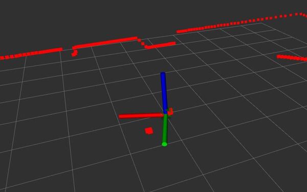
Now set the size to 0.1 so it is easier to see the scans. You can see the scans match up pretty well with the detected objects around the robot in the Gazebo environment.


Let’s look at the IMU information.
Click the “Add” button at the bottom of the RViz window.
Click the “By topic” tab.
Select the “/imu/data” topic so we can view the sensor_msgs/Imu messages.
You will see the IMU orientation and acceleration visualized using the IMU plugin.

Observe how the visualizations change in real-time as your robot moves and interacts with the environment.
ros2 topic pub /mecanum_drive_controller/cmd_vel geometry_msgs/msg/TwistStamped "{
  header: {
    stamp: {sec: `date +%s`, nanosec: 0},
    frame_id: ''
  },
  twist: {
    linear: {
      x: 0.05,
      y: 0.0,
      z: 0.0
    },
    angular: {
      x: 0.0,
      y: 0.0,
      z: 0.0
    }
  }
}"
That’s it! Keep building!

