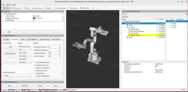
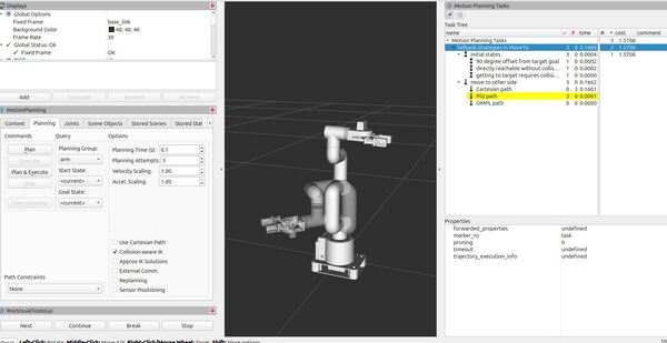
In this tutorial, we will explore how to implement fallback strategies for motion planning using the MoveIt Task Constructor. We’ll create an application from scratch that shows how to plan movements for a robotic arm using multiple planning methods, falling back to more complex methods if simpler ones fail. The output of your application will look like this:
If you prefer to learn by video rather than text, check out this video:
On a high level, your program will demonstrate a robust motion planning approach:
- Defines a target pose for the arm
- Sets up three different initial states using an Alternatives container. The task will try to reach the target pose from each of these initial states, one at a time.
- For each initial state, the task will then try to plan a path to the target pose using the Fallbacks container, which contains three different planners. The task will try these planners in order until one succeeds.
- Cartesian path planning (lowest computational requirements, best for straight-line paths with no obstacles)
- Pilz planning (moderate computational requirements, inherently considers obstacles)
- OMPL planning (high computational requirements, best for complex paths with many obstacles)
- The task uses a “first success” approach. As soon as it finds a valid plan from the initial state to the target pose, regardless of which planning method succeeded, it considers the planning complete and successful. The planner then moves on to generate a plan for the next initial state.
Real-World Use Cases
The code you will develop in this tutorial can serve as a template for various practical applications:
- Pick and Place Operations in Varying Environments
- Use simpler planners for obstacle-free paths
- Fall back to more complex planners when obstacles are present
- Collaborative Robot Tasks
- Start with fast, direct movements when the workspace is clear
- Switch to more careful planning methods when humans or objects enter the workspace
- Flexible Manufacturing
- Adapt to different product configurations by trying multiple planning approaches
- Ensure successful task completion even when the ideal path is blocked
By the end of this tutorial, you’ll have a solid understanding of how to implement fallback strategies in your motion planning tasks, making your robotic applications more robust and adaptable to different scenarios.
Prerequisites
- You have completed this tutorial: Cartesian Path Planning – ROS 2 Jazzy MoveIt Task Constructor
All the code is here on my GitHub repository. Note that I am working with ROS 2 Jazzy, so the steps might be slightly different for other versions of ROS 2.
Create the Code
Open a new terminal window, and type:
cd ~/ros2_ws/src/mycobot_ros2/mycobot_mtc_demos/src/gedit fallbacks_move_to.cppAdd this code.
/**
 * @file fallbacks_move_to.cpp
 * @brief Demonstrates using MoveIt Task Constructor for motion planning with fallback strategies.
 *
 * This program showcases how to use the MoveIt Task Constructor framework to create a motion
 * planning task with multiple initial states and fallback planning strategies. It plans a
 * movement for a robot arm using different planning methods (Cartesian, Pilz, and OMPL).
 *
 * Planning Methods:
 *   - Cartesian path
 *   - Pilz path
 *   - OMPL path
 *
 * @author Addison Sears-Collins
 * @date December 19, 2024
 */

#include <rclcpp/rclcpp.hpp>
#include <moveit/robot_model/robot_model.h>
#include <moveit/planning_scene/planning_scene.h>
#include <moveit/task_constructor/task.h>
#include <moveit/task_constructor/container.h>
#include <moveit/task_constructor/solvers/cartesian_path.h>
#include <moveit/task_constructor/solvers/pipeline_planner.h>
#include <moveit/task_constructor/stages.h>

// Define TAU as 2 * PI for easier angle calculations
constexpr double TAU = 2 * M_PI;

// Use the moveit::task_constructor namespace for convenience
using namespace moveit::task_constructor;

/**
 * @brief Main function to set up and run the MoveIt Task Constructor demo.
 *
 * This function demonstrates how to use the Fallbacks stage to try different planning approaches.
 * It sets up three different initial states and three planning methods (Cartesian, Pilz, and OMPL).
 *
 * @param argc Number of command-line arguments
 * @param argv Array of command-line argument strings
 * @return int Exit status of the program
 */
int main(int argc, char** argv) {
  // Initialize ROS 2
  rclcpp::init(argc, argv);

 // Declare the node parameters
  rclcpp::NodeOptions node_options;
  node_options.automatically_declare_parameters_from_overrides(true);
  node_options.parameter_overrides({
    {"ompl.planning_plugin", "ompl_interface/OMPLPlanner"},
    {"pilz_industrial_motion_planner.planning_plugin", "pilz_industrial_motion_planner/CommandPlanner"}
  });

  // Create the node with the declared parameters
  auto node = rclcpp::Node::make_shared("fallbacks_move_to_demo", node_options);

  // Create a logger
  auto logger = node->get_logger();
  RCLCPP_INFO(logger, "Initializing fallbacks_move_to_demo node");

  // Verify that the parameters are set
  std::string ompl_plugin, pilz_plugin;
  if (node->get_parameter("ompl.planning_plugin", ompl_plugin)) {
    RCLCPP_INFO(logger, "OMPL planning plugin: %s", ompl_plugin.c_str());
  } else {
    RCLCPP_ERROR(logger, "Failed to get OMPL planning plugin parameter");
  }
  if (node->get_parameter("pilz_industrial_motion_planner.planning_plugin", pilz_plugin)) {
    RCLCPP_INFO(logger, "Pilz planning plugin: %s", pilz_plugin.c_str());
  } else {
    RCLCPP_ERROR(logger, "Failed to get Pilz planning plugin parameter");
  }

  // Create a separate thread for spinning the node
  std::thread spinning_thread([node] { rclcpp::spin(node); });

  // Set up the main Task
  Task t;
  t.setName("fallback strategies in MoveTo");
  t.loadRobotModel(node);
  const moveit::core::RobotModelConstPtr robot{ t.getRobotModel() };

  // Ensure we're using the correct robot model
  assert(robot->getName() == "mycobot_280");
  RCLCPP_INFO(logger, "Robot model loaded: %s", robot->getName().c_str());

  // Set up different path planning methods

  // Cartesian path planner (lowest computational requirements, best for straight-line paths with no obstacles)
  auto cartesian = std::make_shared<solvers::CartesianPath>();
  cartesian->setJumpThreshold(2.0);
  RCLCPP_INFO(logger, "Cartesian path planner set up with jump threshold: 2.0");

  // Create PipelinePlanner for Pilz (moderate computational requirements, inherently considers obstacles)
  // Found via -> ros2 service call /query_planner_interface moveit_msgs/srv/QueryPlannerInterfaces "{}"
  std::unordered_map<std::string, std::string> pilz_map = {
    {"pilz_industrial_motion_planner", "PTP"}
  };
  auto pilz_planner = std::make_shared<solvers::PipelinePlanner>(node, pilz_map);
  RCLCPP_INFO(logger, "Pilz planner created");

  // Create PipelinePlanner for OMPL (high computational requirements, best for complex paths with many obstacles)
  std::unordered_map<std::string, std::string> ompl_map = {
    {"ompl", "arm[RRTConnectkConfigDefault]"}
  };
  auto ompl_planner = std::make_shared<solvers::PipelinePlanner>(node, ompl_map);
  RCLCPP_INFO(logger, "OMPL planner created");

  // Define the target end state for all task plans
  std::map<std::string, double> target_state;
  robot->getJointModelGroup("arm")->getVariableDefaultPositions("ready", target_state);
  target_state["link1_to_link2"] = +TAU / 8;
  RCLCPP_INFO(logger, "Target state set for 'arm' group");

  // Define the default initial state
  RCLCPP_INFO(logger, "Setting up initial scene");
  auto initial_scene{ std::make_shared<planning_scene::PlanningScene>(robot) };
  initial_scene->getCurrentStateNonConst().setToDefaultValues(robot->getJointModelGroup("arm"), "ready");

  // Set up three different initial states using an Alternatives container
  RCLCPP_INFO(logger, "Setting up initial state alternatives");
  auto initial_alternatives = std::make_unique<Alternatives>("initial states");

  // First initial state option: 90 degree offset from target goal
  {
    auto fixed{ std::make_unique<stages::FixedState>("90 degree offset from target goal") };
    auto scene{ initial_scene->diff() };
    scene->getCurrentStateNonConst().setVariablePositions({ { "link1_to_link2", -TAU / 8 } });
    fixed->setState(scene);
    initial_alternatives->add(std::move(fixed));
  }

  // Second initial state option: directly reachable without collision
  {
    auto fixed{ std::make_unique<stages::FixedState>("directly reachable without collision") };
    auto scene{ initial_scene->diff() };
    scene->getCurrentStateNonConst().setVariablePositions({
      { "link1_to_link2", +TAU / 8 },
      { "link3_to_link4", 0 },
    });
    fixed->setState(scene);
    initial_alternatives->add(std::move(fixed));
  }

  // Third initial state option: getting to target requires collision avoidance
  {
    auto fixed{ std::make_unique<stages::FixedState>("getting to target requires collision avoidance") };
    auto scene{ initial_scene->diff() };
    scene->getCurrentStateNonConst().setVariablePositions({ { "link1_to_link2", -TAU / 8 } });

    // Add a collision object (box) to the scene
    scene->processCollisionObjectMsg([]() {
      moveit_msgs::msg::CollisionObject co;
      co.id = "box";
      co.header.frame_id = "base_link";
      co.operation = co.ADD;
      co.pose = []() {
        geometry_msgs::msg::Pose p;
        p.position.x = 0.02;
        p.position.y = -0.20;
        p.position.z = 0.32 / 2;
        p.orientation.w = 1.0;
        return p;
      }();
      co.primitives.push_back([]() {
        shape_msgs::msg::SolidPrimitive sp;
        sp.type = sp.BOX;
        sp.dimensions = { 0.005, 0.1, 0.32 };
        return sp;
      }());
      return co;
    }());
    fixed->setState(scene);
    initial_alternatives->add(std::move(fixed));
  }

  // Add the initial states to the task
  RCLCPP_INFO(logger, "Adding initial states to the task");
  t.add(std::move(initial_alternatives));

  // Set up fallback strategies to reach the target state
  RCLCPP_INFO(logger, "Setting up fallback strategies");
  auto fallbacks = std::make_unique<Fallbacks>("move to other side");

  // Helper lambda to add different planning methods to the fallbacks container
  auto add_to_fallbacks{ [&](auto& solver, auto& name) {
    auto move_to = std::make_unique<stages::MoveTo>(name, solver);
    move_to->setGroup("arm");
    move_to->setGoal(target_state);
    fallbacks->add(std::move(move_to));
  } };

  // Add different planning methods to the fallbacks container
  add_to_fallbacks(cartesian, "Cartesian path");
  add_to_fallbacks(pilz_planner, "Pilz path");
  add_to_fallbacks(ompl_planner, "OMPL path");

  // Add the fallback strategies to the task
  RCLCPP_INFO(logger, "Adding fallback strategies to the task");
  t.add(std::move(fallbacks));

  // Plan the task
  RCLCPP_INFO(logger, "Starting task planning");
  try {
    t.plan();
    RCLCPP_INFO(logger, "Task planning completed successfully");
  } catch (const InitStageException& e) {
    RCLCPP_ERROR(logger, "InitStageException caught: %s", e.what());
  } catch (const std::exception& e) {
    RCLCPP_ERROR(logger, "Exception caught: %s", e.what());
  }

  // Wait for the spinning thread to finish (keeps the program running for RViz inspection)
  spinning_thread.join();

  return 0;
}
Save the file, and close it.
Build the Code
cd ~/ros2_ws/colcon buildsource ~/.bashrc Launch
Launch everything:
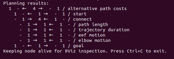
bash ~/ros2_ws/src/mycobot_ros2/mycobot_bringup/scripts/mycobot_280_mtc_demos.sh fallbacks_move_toOR
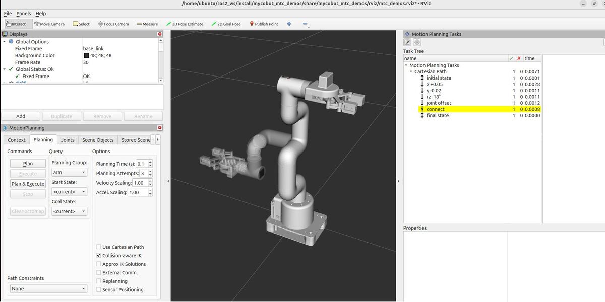
mtc_demos fallbacks_move_toHere is what you should see:
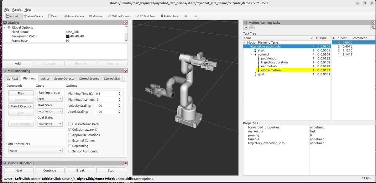
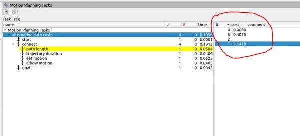
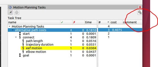
Understanding the Motion Planning Results
RViz – “Motion Planning Tasks” Panel
When running this demo, you’ll see a panel labeled “Motion Planning Tasks” on your screen. This panel shows the structure of each task. Clicking on a stage in this panel will display its outcomes – both successful and failed – in another window. You can then select and visualize individual solutions.

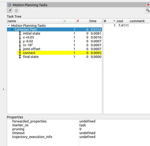
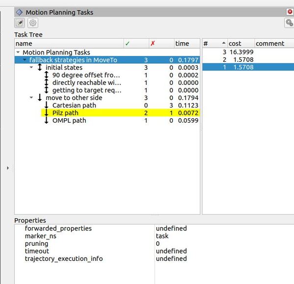
Task Tree
- At the top level is “Motion Planning Tasks”.
- Under this, you’ll find “fallback strategies in MoveTo” – this is our main task.
- The main task has two primary branches:
- “initial states”
- “move to other side”
Initial States
The “initial states” branch represents the three different starting positions we defined in our code:
- “90 degree offset from target goal”
- “directly reachable without collision”
- “getting to target requires collision avoidance”
Each of these has a green checkmark, indicating that all three initial states were successfully processed.
Move to Other Side
The “move to other side” branch is where our fallback strategies are implemented. Here, you’ll see our three planning methods:
- “Cartesian path”
- “Pilz path”
- “OMPL path”
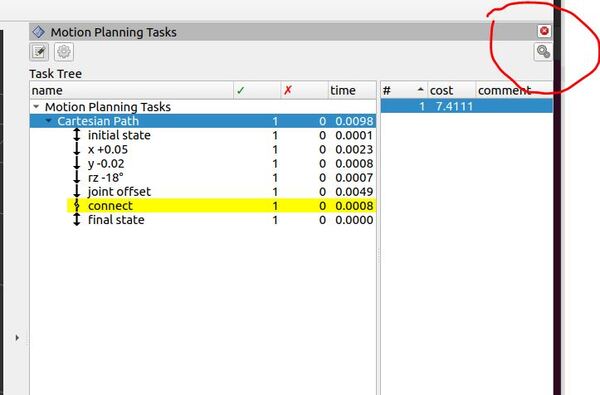
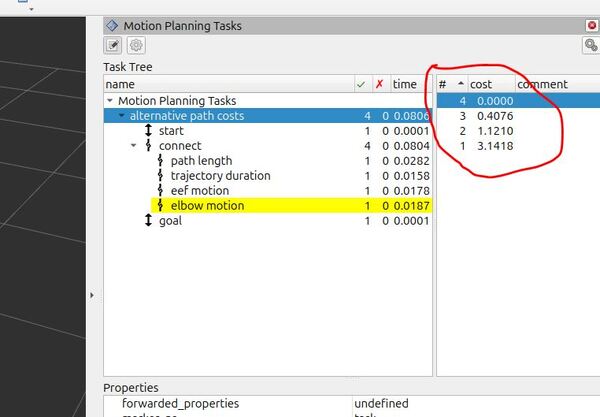
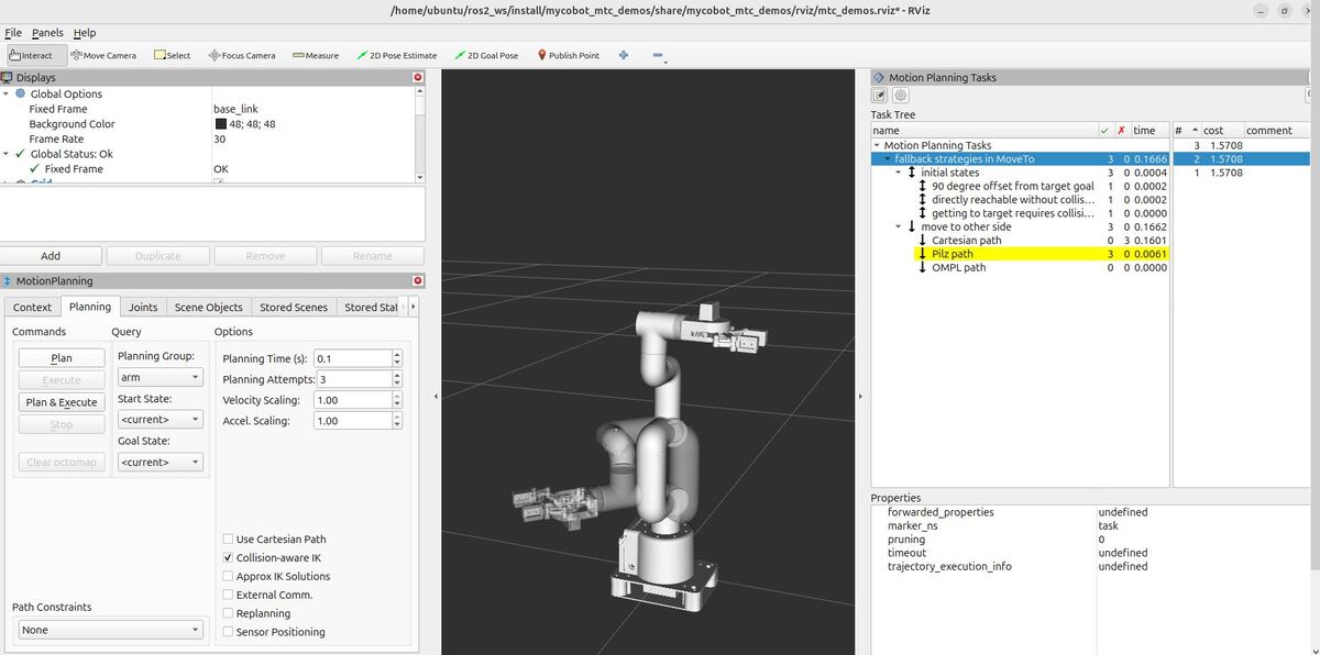
In the example shown:
- The Cartesian path planner failed for all attempts (indicated by the red X and 0 successful solutions).
- The Pilz path planner succeeded for 2 out of 3 initial states (green checkmark, 2 successful solutions).
- The OMPL path planner was successful for the remaining case (1 successful solution for the case where we added an obstacle to the planning scene).
This demonstrates how our fallback strategy works: when simpler methods fail, we progressively try more complex planners until we find a solution.
Planning Time and Performance
The “time” column shows the planning time for each component in seconds:
- The entire task took about 0.1797 seconds.
- Most of this time (0.1794 seconds) was spent in the “move to other side” stage, which is expected as this is where the actual path planning around an obstacle occurs.
- The Pilz path planner took 0.0072 seconds for its successful plans.
- The OMPL path planner took 0.0599 seconds for its successful plan.
These timing details can help you optimize your planning strategy, balancing between faster, simpler planners and more robust, but slower ones.
Analysis of the Results
When it comes to robot motion planning, one size doesn’t fit all. That’s why we implemented a fallback strategy. Let’s break down what we did and what we learned.
Our Lineup of Planners
We used three different motion planners, each with its own strengths:
Cartesian Path Planner: The speedster of the bunch
- Simple and lightning-fast
- Plans straight-line paths in Cartesian space
- Doesn’t worry about obstacles (which can be a problem!)
Pilz Industrial Motion Planner: The middle-ground option.
- Moderately complex
- Specializes in point-to-point (PTP) motions
- Considers obstacles, but isn’t great at planning around them
OMPL (Open Motion Planning Library): The heavy lifter.
- Complex and computationally intensive
- Uses sampling-based algorithms (we used RRTConnect)
- Excels at finding paths in complex, obstacle-ridden environments
The Challenge
We set up three scenarios for our robotic arm:
1. “90 degree offset from target goal”
2. “Directly reachable without collision”
3. “Getting to target requires collision avoidance”
The goal was to see how our planners performed in each case.
The Results: A Planner-by-Planner Breakdown
Looking at our RViz Motion Planning Tasks panel, here’s what we saw. Don’t worry if your output looks slightly different from this:
Cartesian Path Planner: Bad Performer
- Failed all 3 attempts (0 for 3)
Why the total failure? The Cartesian planner is all about straight lines. In the obstacle scenario, it would have plowed right through the box. Even in the “easier” scenarios, if the straight path intersected with the robot’s own body, it was game over.
Pilz Planner: Two Out of Three Isn’t Bad
- Successful for 2 out of 3 attempts
The Pilz planner did well with the “90 degree offset” and “directly reachable” scenarios. Simple point-to-point motions were enough here. But it stumbled on the obstacle course. Our console showed the evidence:
[ERROR] [1725039186.392887391] [moveit.ros_planning.planning_pipeline]: Computed path is not valid. Invalid states at index locations: [ 4 5 ] out of 13.
[INFO] [1725039186.392943008] [moveit_collision_detection_fcl.collision_common]: Found a contact between ‘box’ (type ‘Object’) and ‘link6_flange’ (type ‘Robot link’), which constitutes a collision.
In other words, it found a path, but it was a path straight through our obstacle. Not exactly what we want in a real-world scenario!
OMPL: Great for Complicated Situations
- Succeeded in its single attempt
OMPL came in clutch for the scenario that stumped the others. Its sampling-based approach allowed it to “think outside the box” (pun intended) and find a path around our obstacle.
The Big Picture
This experiment demonstrates why fallback strategies in motion planning are important:
1. Efficiency: We start with fast, simple planners for easy scenarios. It is like solving a maze – you begin with a straightforward path, and only pull out the elaborate strategy guide when you hit a dead end.
2. Robustness: When the simple approaches fail, we escalate to more sophisticated methods. This ensures we can handle whatever the environment throws at us.
3. Adaptability: Our system automatically adjusts to the complexity of the task. It’s like having a Swiss Army knife of motion planning.
By structuring our planning pipeline this way, we get the best of all worlds: speed when possible, and the ability to tackle complex situations when needed. It is this kind of adaptability that takes robotic systems from laboratory curiosities to real-world problem solvers.
Detailed Code Walkthrough
Now for the C++ part. Let’s go through each piece of this code, step by step.
cd ~/ros2_ws/src/mycobot_ros2/mycobot_mtc_demos/src/gedit fallbacks_move_to.cppLet’s explore each component of this code in detail.
File Header and Includes
The code begins with a comprehensive comment block outlining the file’s purpose: demonstrating motion planning with fallback strategies using MoveIt Task Constructor. It describes the program’s functionality, which creates a movement for a robotic arm using different planning methods (Cartesian, Pilz, and OMPL). The file includes necessary headers for ROS 2, MoveIt, and the Task Constructor library, establishing the foundation for our robot motion planning task.
Main Function
All the logic for this program is contained within the main function. Let’s break it down into its key components:
ROS 2 Initialization and Node Setup
The code initializes ROS 2 and creates a node named “fallbacks_move_to_demo”. It sets up node options and parameters for OMPL and Pilz planners, and creates a logger for informational output. This setup ensures proper communication within the ROS 2 ecosystem.
Robot Model Loading
A Task object is created, and the robot model is loaded. The code verifies the correct robot model (“mycobot_280”) is loaded. This step is important for accurate motion planning based on the specific robot’s characteristics.
Planner Setup
Three different planners are configured:
- Cartesian path planner: Set up with a jump threshold for straight-line movements. A jump threshold is a limit set on how much a robot’s joints can change their positions between two consecutive points along a planned path. It is measured in radians for rotational joints.
- Pilz industrial motion planner: Configured for point-to-point motions.
- OMPL planner: Set up for complex path planning scenarios.
Each planner is tailored to handle different aspects of motion planning, from simple straight-line movements to complex obstacle avoidance.
Target State Definition
The code defines the target end state for all task plans. It sets a specific joint angle for the “link1_to_link2” joint, establishing the goal configuration for the robotic arm.
Initial States Setup
An Alternatives container is created to hold three different initial states:
- 90-degree offset from the target goal
- A state directly reachable without collision
- A state requiring collision avoidance (including a box obstacle)
This variety of initial states allows the planner to demonstrate its versatility in different scenarios.
Fallback Strategies Setup
A Fallbacks container named “move to other side” is created. The three planning methods (Cartesian, Pilz, and OMPL) are added to this container. Each planner is configured to move the “arm” group to the target state. This setup allows the system to try different planning strategies if earlier attempts fail.
Task Planning and Execution
The code attempts to plan the task using the defined fallback strategies. It includes error handling for potential exceptions during planning, ensuring robustness in various scenarios.
Node Spinning
A separate thread is created for spinning the ROS 2 node. This allows the program to handle callbacks and events while performing its main tasks.
That’s it! Keep building!