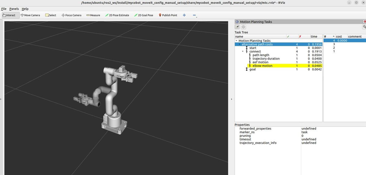
There are six demos that come out of the box with the ROS 2 move_it_task_constructor_demo package. However, these demos are tailored for another robotic arm. We need to tailor these for our robotic arm.
In this tutorial, we will create the first demo from scratch…alternative_path_costs.cpp.
Here is what the output looks like:
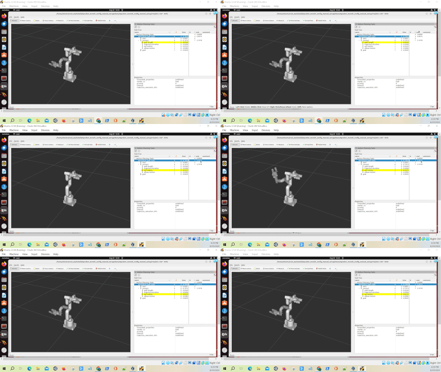
alternative_path_costs.cpp showcases different ways to plan and evaluate robot arm movements. It goes through four different methods for moving the robotic arm from a starting position to a predefined goal position:
- The shortest path
- The quickest movement
- A path focusing on minimal end-effector (gripper) motion
- A path that minimizes movement of a specific part of the arm (like the elbow).
Real-World Use Cases
The code you will develop in this tutorial can serve as a template for some practical real-world applications:
- Precision Manufacturing
- Minimize end-effector motion for delicate assembly tasks
- Optimize trajectory duration to increase production speed
- Reduce wear on joints by minimizing overall path length
- Collaborative Robotics
- Plan predictable movements by minimizing elbow motion, enhancing worker safety
- Adjust strategies based on the task: quick movements for time-sensitive operations or smooth motions for human comfort
- Flexible Manufacturing Systems
- Quickly adapt arm movements to different product specifications
- Switch between optimization strategies (e.g., speed vs. precision) based on current production needs
Prerequisites
- You have completed this tutorial.
All the code is here on my GitHub repository. Note that I am working with ROS 2 Iron, so the steps might be slightly different for other versions of ROS 2.
Create the Code
Open a new terminal window, and type:
cd ~/ros2_ws/src/mycobot_ros2/hello_moveit_task_constructor/src/gedit alternative_path_costs.cppAdd this code.
/**
 * @file alternative_path_costs.cpp
 * @brief Demonstrates different path planning strategies using MoveIt Task Constructor.
 *
 * This program sets up a Task Constructor task to plan robot motion using different
 * cost optimization strategies. It creates multiple path planning alternatives and
 * evaluates them based on different cost terms such as path length, trajectory duration,
 * end-effector motion, and elbow motion.
 *
 * @author Addison Sears-Collins
 * @date August 16, 2024
 */


#include <rclcpp/rclcpp.hpp>
#include <moveit/planning_scene/planning_scene.h>
#include <moveit/task_constructor/task.h>
#include <moveit/task_constructor/container.h>
#include <moveit/task_constructor/solvers/pipeline_planner.h>
#include <moveit/task_constructor/stages/connect.h>
#include <moveit/task_constructor/stages/fixed_state.h>
#include <moveit/task_constructor/cost_terms.h>
#include <iostream>

using namespace moveit::task_constructor;

/**
 * @brief Main function to demonstrate alternative path costs.
 *
 * This function sets up a ROS 2 node, creates a Task Constructor task,
 * and demonstrates different path planning strategies using various cost terms.
 * FixedState (Generator Stage) - Connect (Connector Stage) - FixedState (Generator Stage)
 *
 * @param argc Number of command-line arguments
 * @param argv Array of command-line arguments
 * @return int Exit status
 */
int main(int argc, char** argv) {
    // Initialize ROS 2
    rclcpp::init(argc, argv);
    std::cout << "ROS 2 initialized for alternative_path_costs_demo" << std::endl;

    // Set up ROS 2 node options
    rclcpp::NodeOptions node_options;
    node_options.automatically_declare_parameters_from_overrides(true);

    // Create a ROS 2 node
    auto node = rclcpp::Node::make_shared("alternative_path_costs_demo", node_options);
    std::cout << "Created ROS 2 node: alternative_path_costs_demo" << std::endl;

    // Start a separate thread to handle ROS 2 callbacks
    std::thread spinning_thread([node] { rclcpp::spin(node); });

    // Create a Task Constructor task
    Task t;
    t.stages()->setName("alternative path costs");
    std::cout << "Created Task Constructor task: alternative path costs" << std::endl;

    // Load the robot model
    t.loadRobotModel(node);
    std::cout << "Loaded robot model: " << t.getRobotModel()->getName() << std::endl;

    // Ensure the correct robot model is loaded
    assert(t.getRobotModel()->getName() == "mycobot_280");

    // Create a planning scene
    auto scene{ std::make_shared<planning_scene::PlanningScene>(t.getRobotModel()) };
    std::cout << "Created planning scene" << std::endl;

    // Get the current robot state and set it to default values
    auto& robot_state{ scene->getCurrentStateNonConst() };
    robot_state.setToDefaultValues();
    robot_state.setToDefaultValues(robot_state.getJointModelGroup("arm"), "home");
    std::cout << "Initialized robot state in planning scene to default values and 'home' position" << std::endl;

    // Create and add the initial state to the task
    // This step gives MoveIt 2 a clear starting point from which to plan the robot's movements.
    auto initial{ std::make_unique<stages::FixedState>("start") };
    initial->setState(scene);
    t.add(std::move(initial));
    std::cout << "Added initial state to the task" << std::endl;

    // Create a pipeline planner
    // The "pipeline" part means it can chain together multiple planning attempts or strategies.
    // If one method fails, it can try another
    auto pipeline{ std::make_shared<solvers::PipelinePlanner>(node) };
    std::cout << "Created pipeline planner" << std::endl;

    // Create an Alternatives container for different path planning strategies
    // Alternatives container is a type of Parallel container. It's used to group multiple stages that
    // represent different ways to accomplish the same task.
    // In this case, it's used to create different strategies for connecting the intial state to the goal state.
    // The planner will try all these strategies and choose the best one based on their respective cost terms.
    auto alternatives{ std::make_unique<Alternatives>("connect") };
    std::cout << "Created Alternatives container for path planning strategies" << std::endl;

    // Add different path planning strategies (Connect stages) to the Alternatives container
    // Each strategy uses a different cost term to evaluate the path

    // Strategy 1: Minimize path length
    {
      auto connect{ std::make_unique<stages::Connect>(
           "path length", stages::Connect::GroupPlannerVector{ { "arm_with_gripper", pipeline } }) };
      connect->setCostTerm(std::make_unique<cost::PathLength>()); //  Typically in radians, representing the total angular displacement of all joints.
      alternatives->add(std::move(connect));
      std::cout << "Added 'path length' strategy" << std::endl;
    }

    // Strategy 2: Minimize trajectory duration
    {
      auto connect{ std::make_unique<stages::Connect>(
           "trajectory duration", stages::Connect::GroupPlannerVector{ { "arm_with_gripper", pipeline } }) };
      connect->setCostTerm(std::make_unique<cost::TrajectoryDuration>()); // Time it would take in seconds to execute the planned motion.
      alternatives->add(std::move(connect));
      std::cout << "Added 'trajectory duration' strategy" << std::endl;
    }

    // Strategy 3: Minimize end-effector motion
    {
      auto connect{ std::make_unique<stages::Connect>(
           "eef motion", stages::Connect::GroupPlannerVector{ { "arm_with_gripper", pipeline } }) };
      connect->setCostTerm(std::make_unique<cost::LinkMotion>("link6_flange")); // Distance traveled by the link in meters
      alternatives->add(std::move(connect));
      std::cout << "Added 'end-effector motion' strategy" << std::endl;
    }

    // Strategy 4: Minimize elbow motion
    {
      auto connect{ std::make_unique<stages::Connect>(
           "elbow motion", stages::Connect::GroupPlannerVector{ { "arm_with_gripper", pipeline } }) };
      connect->setCostTerm(std::make_unique<cost::LinkMotion>("link3"));
      alternatives->add(std::move(connect));
      std::cout << "Added 'elbow motion' strategy" << std::endl;
    }

    // Add the Alternatives container to the task
    // By adding this Alternatives container to the task, we're giving the task planner multiple options for
    // solving a particular part of the robot's movement. The planner can now choose the best strategy based on the current situation.
    t.add(std::move(alternatives));
    std::cout << "Added all strategies in the Alternatives Container to the task" << std::endl;

    // Create the goal scene as a diff from the current scene
    // Think of this like taking a snapshot of the current room (scene) and then describing only what
    // needs to change to reach the desired setup.
    // In our goal setup, we want the robot's arm and gripper to be in the 'ready' position."
    auto goal_scene{ scene->diff() };
    goal_scene->getCurrentStateNonConst().setToDefaultValues(robot_state.getJointModelGroup("arm_with_gripper"), "ready");
    std::cout << "Created goal scene with 'ready' position" << std::endl;

    // Create and add the goal state to the task
    auto goal = std::make_unique<stages::FixedState>("goal");
    goal->setState(goal_scene);
    t.add(std::move(goal));
    std::cout << "Added goal state to the task" << std::endl;

    // Plan the task
    std::cout << "Starting task planning..." << std::endl;
    try {
      t.plan(0); // The 0 parameter means it will generate as many solutions as possible
      std::cout << "Task planning completed successfully" << std::endl;

      // Print the results
      std::cout << "Planning results:" << std::endl;
      t.printState();

    } catch (const InitStageException& e) {
        std::cout << "Task planning failed: " << e << std::endl;
    }

    // Keep the node alive for interactive inspection in RViz
    std::cout << "Keeping node alive for RViz inspection. Press Ctrl+C to exit." << std::endl;
    spinning_thread.join();

    return 0;
}
Save the file, and close it.
Build the Code
cd ~/ros2_ws/colcon buildsource ~/.bashrc
(OR 'source ~/ros2_ws/install/setup.bash' if you haven’t set up your bashrc file to source your ROS distribution automatically with “source ~/ros2_ws/install/setup.bash”)Launch
Open two terminal windows, and run the following commands to launch our standard MoveIt 2 environment:
ros2 launch mycobot_gazebo mycobot_280_arduino_bringup_ros2_control_gazebo.launch.py use_rviz:=falseros2 launch hello_moveit_task_constructor demo.launch.pyIn separate terminal windows, run one of the demos. Let’s see what launch options we have:
ros2 launch hello_moveit_task_constructor run.launch.py --show-argsNow run the demo:
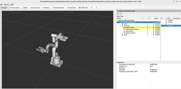
ros2 launch hello_moveit_task_constructor run.launch.py exe:=alternative_path_costsHere is what you should see:
Understanding the Motion Planning Results
RViz – “Motion Planning Tasks” Panel
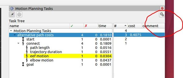
When running this demo, you’ll see a panel labeled “Motion Planning Tasks” on your screen. This panel shows the structure of each task. Clicking on a stage in this panel will display its outcomes – both successful and failed – in another window. You can then select and visualize individual solutions.
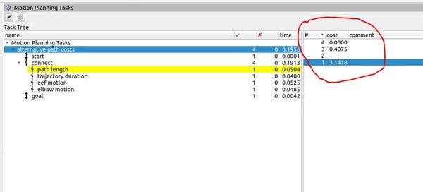
The Task Tree in the panel reflects the structure of our program. At the top, you’ll see “Motion Planning Tasks” with “alternative path costs” underneath. This corresponds to our main task, which is designed to explore different path planning strategies.
The task is divided into three main stages: “start,” “connect,” and “goal.” These stages represent the robot’s initial position (set to the “home” position in our code), the motion it needs to perform, and its final position (set to the “ready” position).
The “connect” stage is where the magic happens. In our code, we’ve created an Alternatives container with four different planning strategies:
1. “path length“: This strategy aims to minimize the total angular displacement of all joints, measured in radians.
2. “trajectory duration“: This strategy tries to find the quickest path, minimizing the time it would take to execute the planned motion.
3. “eef motion“: This strategy focuses on minimizing the distance traveled by the end-effector (the robot’s “hand”), which in our code is represented by the “link6_flange”.
4. “elbow motion“: Similar to the end-effector strategy, but focusing on minimizing the movement of the robot’s elbow (represented by “link3” in our code).
The green checkmarks and numbers in the second column indicate how many successful solutions were found for each part of the task.
For example, if you see a “4” next to “alternative path costs,” it means our planner successfully found solutions using all four strategies.
The rightmost column displays the planning time for each component in seconds. This column helps us understand which strategies might be more computationally intensive.
As you experiment with the demo, try clicking on the “alternative path costs” line under the Task Tree. Then select each of the four different solutions to see how the robotic arm moves. You’ll be able to visualize how each strategy results in different robot motions, helping you understand the trade-offs between path length, speed, and the movement of specific parts of the robot.
If you actually want to execute a particular solution, click the “Execute Solution” button in the upper-right part of the panel.
Terminal Window – Planning Results
If you look at the terminal window, you will see the planning results.
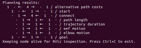
MoveIt Task Constructor uses a bidirectional planning approach. This means it can work on a problem from both ends – the start stage and the goal stage – simultaneously.
- Forward: When the planner finds a good partial solution from the start, it sends this information forward to help plan the next stages.
- Backward: When it finds a good approach to the goal, it sends this information backward to influence earlier stages of the plan.
Arrow Interpretation
- → (Right Arrow): Represents the forward flow of results from one stage to the next. Forward flow means that a stage has successfully generated a result and is passing that result to the next stage for further processing.
- ← (Left Arrow): Indicates a backward flow of results. In MTC, some stages may require feedback from later stages to adjust their own results or to optimize the plan. Therefore, the results flow backward to a previous stage for this adjustment.
- – (Dash): A dash indicates no information flowed in that direction.
When a solution is found in one stage, it might impose constraints on other stages. Propagating the solution backwards allows earlier stages to take these constraints into account, potentially leading to better overall solutions.
A good example of the benefits of bidirectional planning is a pick and place task. Imagine you want a robotic arm to pour water from a cup into a pot. You want to make sure that early stages don’t generate movements that would put the arm in a position where grasping the cup to do a pouring movement is difficult or infeasible.
This unidirectional approach could result in less efficient movements, more frequent replanning, or even failure to complete the task if a viable path from start to finish isn’t found. Overall, the lack of foresight into future stages could lead to suboptimal or unsuccessful attempts at completing the pick and place task.
In our particular application, for the “start” stage, we see 1 – ← 1 → – 1. This line indicates that our start state (the “home” position we set) was successfully created, with one solution propagated forward to the connect stage and one solution propagated backwards to the initial stage at t=0.
The “connect” stage, where our four strategies are implemented, displays – 1 → 4 ← 1 -. This line means it received one solution propagated forward from the start, generated four alternative solutions (one for each strategy), and received one solution propagated backward from the goal.
Looking at our individual strategies:
- “path length”: – 1 → 1 ← 1 –
- “trajectory duration”: 1 → 1 ← 1 –
- “eef motion”: 1 → 1 ← 1 –
- “elbow motion”: 1 → 1 ← 1 –
Each strategy successfully received one solution from the start, generated its own solution, and received one solution from the goal. These results indicate that each strategy successfully connected the start and goal stage.
The “goal” stage shows 1 – ← 1 → – 1, confirming that the final state (our “ready” position) was successfully incorporated into the planning process, propagating one solution backward to the connect stage and one solution forward to t=final.
These results demonstrate that our planner effectively generated and evaluated multiple paths using different optimization criteria. It successfully planned motions from the home position to the ready position using each strategy, considering both the start and goal states in its calculations. This bidirectional approach (planning from both start and goal) often leads to more efficient and robust motion planning.
By examining these different solutions in RViz, you can observe how prioritizing path length, duration, end-effector motion, or elbow motion affects the robot’s planned movement, providing valuable insights into the trade-offs between different motion planning approaches.
Detailed Code Walkthrough
Now for the C++ part. Let’s go through each piece of this code, step by step.
cd ~/ros2_ws/src/mycobot_ros2/hello_moveit_task_constructor/src/gedit alternative_path_costs.cppFile Header and Includes
The code begins with a comprehensive comment block explaining the file’s purpose: demonstrating various path planning strategies using MoveIt Task Constructor. It outlines the program’s functionality, creating multiple planning alternatives and evaluating them based on different cost terms like path length and trajectory duration. The file includes necessary headers for ROS 2, MoveIt, and the Task Constructor library, setting up the foundation for our robot motion planning task.
Main Function
The main function serves as the entry point and primary workflow of the program. It orchestrates the setup of the ROS 2 environment, task creation, and implementation of planning strategies.
ROS 2 Initialization
The code initializes ROS 2, creating a computational environment for robot control. It then sets up a node named “alternative_path_costs_demo”. This node acts as a communication endpoint within the ROS 2 system.
A separate thread is created to handle ROS 2 callbacks. Callbacks are functions that are automatically called in response to specific events or messages in the ROS 2 system. By running callbacks in a separate thread, the program can continue its main planning tasks without interruption, while still responding to incoming messages or events. This approach enhances the system’s ability to multitask effectively.
Task Creation and Robot Model Loading
The code creates a Task Constructor task, naming it “alternative path costs”. This task will encompass all the planning stages and strategies. It then loads the robot model for our robotic arm. This step provides the task with detailed information about the robot’s physical structure, joint limits, and other characteristics necessary for accurate motion planning.
Planning Scene Setup
A planning scene is created based on the loaded robot model. This virtual environment represents the space in which the robot operates and where motion planning will occur. The robot’s initial state within this scene is set to default values, with the “arm” group specifically positioned in a predefined “home” position. This setup ensures a consistent starting point for all planning attempts.
Initial State Creation
The code creates an initial state named “start” as a FixedState stage. This stage is added to the task and represents the starting configuration of the robot. It serves as a key reference point from which all motion plans will begin.
Pipeline Planner Creation
The code creates a PipelinePlanner, a planning tool that interfaces with MoveIt’s PlanningPipeline. This planner can use multiple planning algorithms and post-processing steps. It includes features like planner caching for efficiency, customizable planning parameters (e.g., number of attempts, workspace parameters, goal tolerances), and options for displaying motion plans and publishing planning requests.
That’s it! Congratulations on getting your feet wet with a real application using the MoveIt Task Constructor. Stay tuned for more projects.
Keep building!

