In the previous tutorial, we created the configuration files for MoveIt manually from scratch. Creating the MoveIt configuration files manually provides a deeper understanding of the system’s structure and enables you to configure MoveIt just how you want.
An alternative way of creating these configuration files is to use the MoveIt Setup Assistant.
I strongly recommend you create the MoveIt config package manually if you are using Gazebo because the MoveIt Setup Assistant demo.launch.py file doesn’t work straight out of the box (as of the time of this writing). You can also use MoveIt Setup Assistant to generate the configuration files, and then you can copy the files over to your own manually created package.
I’ll walk you through the configuration file generation process in this tutorial.
The official tutorial is here, but I will walk you through all the steps below.
Follow along with me step by step, mouse click by mouse click, keystroke by keystroke as we explore how to use this tool to integrate your robotic arm with MoveIt 2 and ROS 2.
Prerequisites
- You have completed this tutorial (strongly recommended).
- You have a URDF/XACRO file for your robotic arm.
Directions
Load the URDF
Everything starts with the URDF/XACRO file. Once you have your URDF, you are ready to use the MoveIt Assistant.
If you don’t have a URDF, you will need to create one.
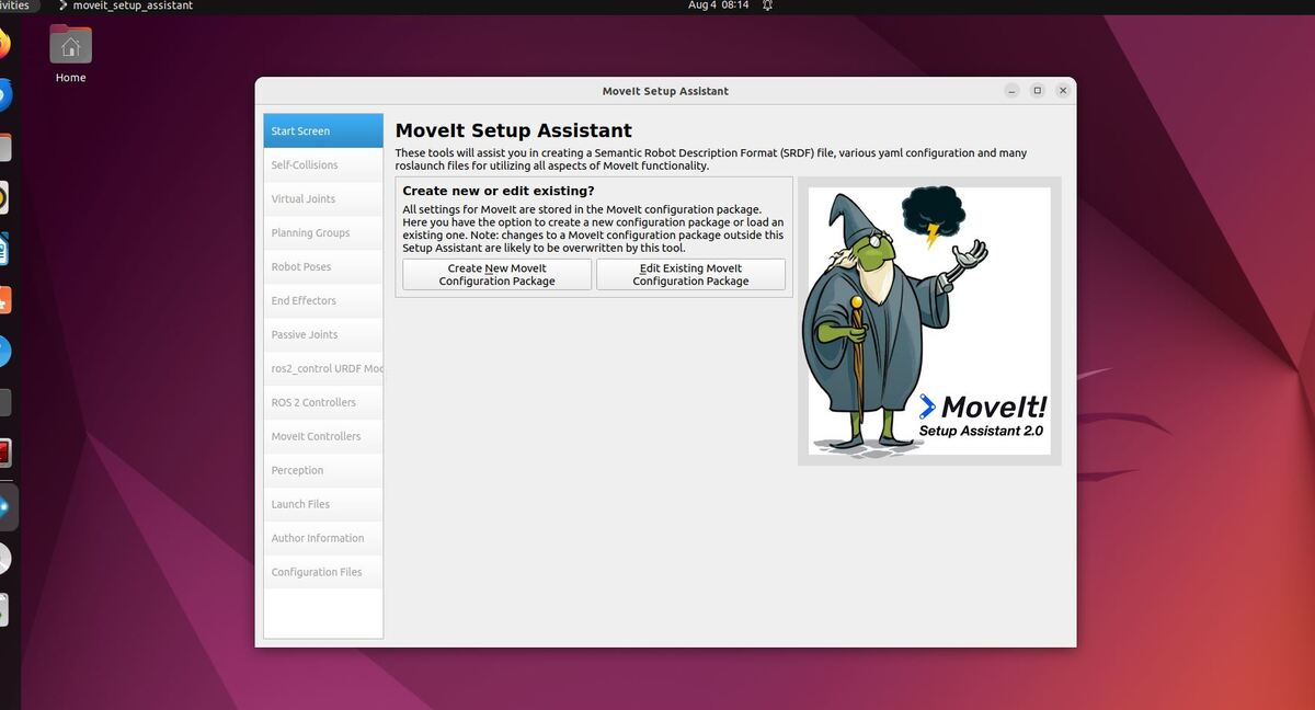
Open a terminal window, and launch the MoveIt Setup Assistant:
ros2 launch moveit_setup_assistant setup_assistant.launch.py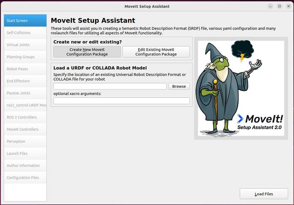
You now have two choices:
- Create New MoveIt Configuration Package
- Edit Existing MoveIt Configuration Package.
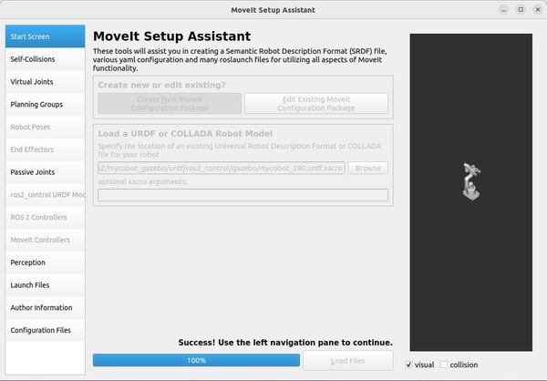
Click on the Create New MoveIt Configuration Package button to bring up the following screen:
Click Browse, and find the XACRO file for the robotic arm.
/home/ubuntu/ros2_ws/src/mycobot_ros2/mycobot_gazebo/urdf/ros2_control/gazebo/mycobot_280.urdf.xacroChoose the file.
Click Load Files.
Wait for the Setup Assistant to load the files.
When it is done, you will see this screen:
Generate the Self-Collision Matrix
In this section, we will generate the self-collision matrix.
The Self-Collision matrix generator in MoveIt 2 helps speed up motion planning by identifying which parts of the robotic arm are safe to ignore when checking for collisions. It does this by randomly putting the robot in different positions and checking which parts collide with each other, are always colliding, never collide, or are next to each other.
By increasing the number of random positions checked (sampling density), the collision checking results become more accurate, but the process takes longer.
Select the Self-Collisions pane on the left-hand side of the MoveIt Setup Assistant.
Let’s set the self-collision sampling density to somewhere in the middle of the slider.
Now click Generate Collision Matrix. This step will check for pairs of links on your robotic arm that can be safely ignored for collision checking.
Let’s take a look at the results.
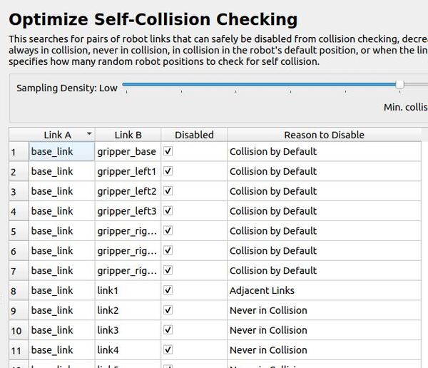
Collision by Default: This means the system assumes these parts might collide unless told otherwise. It’s like being extra careful by default.
Adjacent Links: These are parts that are right next to each other on the robot. The system usually doesn’t need to check if they’ll collide because they’re designed to move together.
Never in Collision: This means these parts are so far apart or positioned in a way that they can never hit each other, so the system doesn’t need to check them.
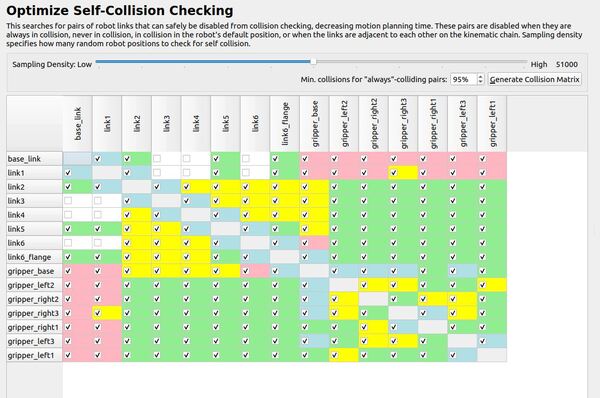
Click matrix view.
If you see a checkmark in the box, that means the robot won’t check for collisions between those two parts. But if you want it to start checking, just click the checkbox to remove the checkmark. Doing this will turn collision checking on for that pair of parts.
I am really concerned about the big parts of the robot (i.e. link 3 and 4, which are the “meat” of the arm) colliding with the base of the robot. You can see my final matrix here:
Add Virtual Joints
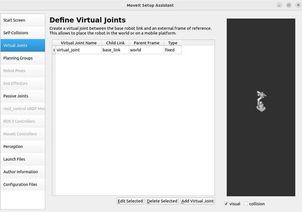
Now let’s add a virtual joint. A virtual joint’s purpose is to connect the robotic arm to the world.
For our robotic arm, we will attach the base_link of the robotic arm to the world coordinate frame. This virtual joint means that the base of the robotic arm will remain stationary in the world frame.
Click on the Virtual Joints pane selector on the left-hand side of the window.
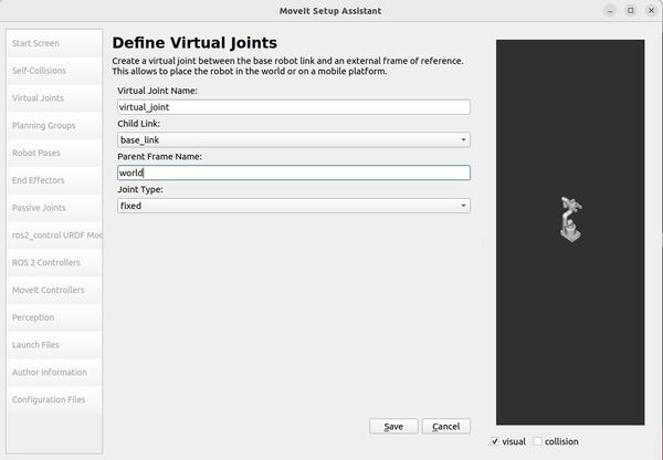
Click Add Virtual Joint.
Set the Virtual Joint Name to virtual_joint.
Set the Child Link to base_link.
Set the Parent Frame Name to the world.
Set the Joint Type to fixed.
Click Save.
There is a note on the MoveIt 2 website about how to define virtual joints for a mobile manipulator.
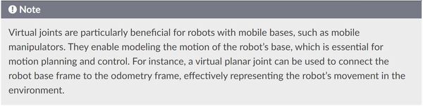
For a mobile manipulator, we would create a virtual joint to connect the mobile robot’s base to the odometry frame.
Here is how you might configure this:
- Parent Frame: This would be the odometry frame, usually named odom.
- Child Frame: This would be the mobile robot base (usually called base_link)
Here is an example configuration for this type of virtual joint:
- Joint Name: virtual_joint
- Parent Frame: odom
- Child Link: base_link
- Joint Type: planar
The planar joint allows for motion in the x and y directions and rotation about the z-axis, which is typical for mobile bases operating on a plane.
This configuration effectively models the motion of the robot’s mobile base relative to its odometry frame, which is important for accurate motion planning and control in a dynamic environment.
Add Planning Groups
Now it is time to add planning groups.
When you want a robot to move a specific part of its body, like an arm, a gripper, or a hand, you need to tell the computer which parts of the robot should move together. This is where “planning groups” come into play.
A planning group is a way to describe a specific part of the robot to the computer. It’s like giving a name to a collection of robot parts that work together for a particular motion.
For example, if you have a robot with an arm and a gripper, you could create two planning groups: “arm” and “gripper.”
The arm group would include all the necessary links (the solid parts of the robot) and joints (the movable connections between the links) that make up the arm. By doing this, you’re telling the computer, “When I say ‘move the arm,’ I mean move all these specific parts together.”
Similarly, for the gripper group, you would include all the links and joints needed for the gripper to open and close.
Planning groups make it easier to control the robot’s motions by allowing you to give simple commands like “move the arm to the home position,” “open the gripper,” or “make a fist,” instead of having to control each individual link and joint separately. This way, you can focus on the overall movement you want the robot to make, and let the computer take care of the details of moving the right parts in the right way.
We are going to add three planning groups to our robot: arm, gripper, and arm_with_gripper.
First, click on the Planning Groups pane selector.
Click on Add Group.
Add the Arm Group
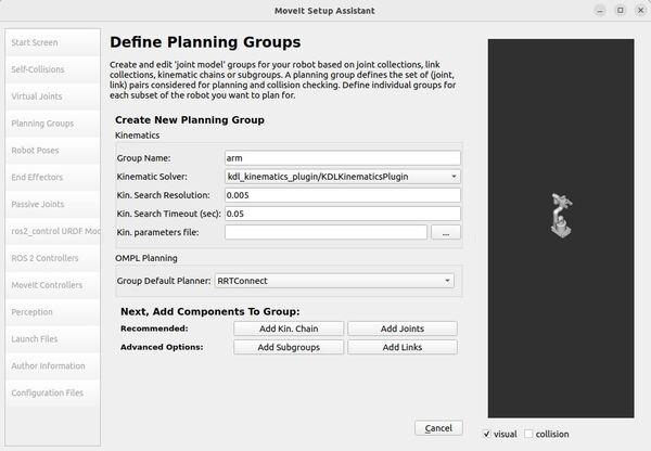
Let’s start by adding the arm group.
Enter the Group Name as arm.
Choose kdl_kinematics_plugin/KDLKinematicsPlugin as the kinematics solver.
The KDLKinematicsPlugin helps determine how a robotic arm should move its joints to reach a certain position or follow a certain path.
For example, if you want the robot’s arm to reach out and press a button or move to pick up an object, this plugin calculates the best way to achieve that by adjusting the angles of the joints.
Let me briefly explain all the options on the dropdown list.
KDLKinematicsPlugin
The KDLKinematicsPlugin is the default for MoveIt2 due to its reliability and comprehensive support for various robot configurations. It ensures joint limit compliance as specified in URDF files, making it versatile for many applications.
CachedKDLKinematicsPlugin
This plugin is ideal for applications where IK solutions are frequently reused, such as in repetitive pick-and-place tasks, as it speeds up calculations by caching previous solutions.
CachedSrvKinematicsPlugin
This plugin would be useful when you have a custom kinematics service that you want to cache for improved performance. It is ideal when you have complex or custom kinematics that aren’t easily solved by standard libraries, but you still want to benefit from caching for faster repeated calculations.
LMAKinematicsPlugin
The LMAKinematicsPlugin is particularly useful for industrial robots with multiple redundant joints, such as 7-DOF robotic arms used in advanced manufacturing. It is valuable for robots that need to perform complex tasks in tight spaces, like welding in automotive assembly lines or intricate pick-and-place operations in electronics manufacturing. This plugin can also be beneficial for research robots or prototypes with unconventional designs where standard kinematics solvers struggle to find valid solutions.
SrvKinematicsPlugin
The SrvKinematicsPlugin is used when you have a custom kinematics solver that runs as a separate service outside of MoveIt 2.
This setup is useful in two main scenarios:
- When working with proprietary robots where the manufacturer provides a “black box” kinematics solver that can’t be directly integrated into MoveIt’s codebase.
- In research environments where you’re experimenting with novel kinematics algorithms and want to keep them separate from MoveIt for easier development and testing.
By using this plugin, you can connect MoveIt 2 to your external kinematics service, allowing MoveIt to use your custom solver without needing to modify MoveIt’s core code.
Let Kin. Search Resolution be 0.005 and Kin. Search Timeout be 0.05.
The Kinematic Search Resolution parameter represents the precision with which the robotic arm searches for the correct joint positions. A value of 0.005 means that the robot makes adjustments in increments of 0.005 units (typically in radians or meters, depending on the context), meaning the robot will make small, precise adjustments to find the correct position for its movements.
The Kinematic Search Timeout represents the maximum amount of time the robotic arm will spend trying to find the correct joint positions before giving up. A timeout of 0.05 means that the robotic arm will only attempt to find the correct position for 0.05 seconds before stopping its search.
Set the Group Default Planner for OMPL Planning to RRTConnect.
RRTConnect stands for Rapidly-exploring Random Tree Connect. The algorithm works by growing two trees simultaneously – one from the start pose and one from the goal pose. It attempts to connect these trees to find a valid path.
RRTConnect is a good general-purpose planner, and you will see it as the default planner in a lot of MoveIt configuration packages you find on GitHub.
Now click on the Add Joints button.
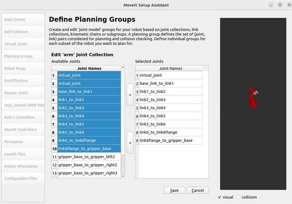
You will see a list of the joints in the left column of the panel.
To choose all joints that belong to the robotic arm and add them to the right column, you need to:
- Click on virtual_joint.
- Hold down the shift button on your keyboard.
- Click on the last joint of the robotic arm group. It is called link6flange_to_gripper_base.
- Click the > button to add the joints to the Selected Joints column.
Click Save.
Here is the list of our arm group joints:
joints:
- virtual_joint
- link1_to_link2
- link2_to_link3
- link3_to_link4
- link4_to_link5
- link5_to_link6
- link6_to_link6flange
Add the Gripper Group
Now let’s add the group for the gripper on the robotic arm.
Click on the Add Group button.
Our Group Name will be gripper.
Our gripper is a simple open-close mechanism that doesn’t require complex motion planning. It can be controlled without needing a Kinematic Solver to calculate its trajectories.
Select None for Kinematic Solver.
Keep Kin. Search Resolution and Kin. Search Timeout at their default values.
Click the Add Links button.
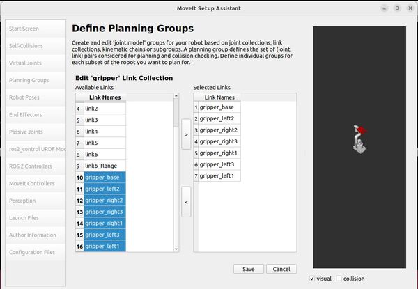
Select the following links, and add them to the list of Selected Links on the right-hand side:
- gripper_base
- gripper_left1
- gripper_left2
- gripper_left3
- gripper_right1
- gripper_right2
- gripper_right3
In this automatic setup, we will use links instead of joints for the gripper planning group because it’s easier to plan and control the gripper’s movements based on the positions of the gripper links. This approach simplifies grasping and collision checking.
Click Save.
Add the Arm with Gripper Group
Finally, let’s add the arm_with_gripper group.
Click on the Add Group button.
Our Group Name will be arm_with_gripper.
Our gripper is a simple open-close mechanism that doesn’t require complex motion planning. It can be controlled without needing a Kinematic Solver to calculate its trajectories.
Choose kdl_kinematics_plugin/KDLKinematicsPlugin as the kinematics solver.
Keep Kin. Search Resolution at 0.005.
Change Kin. Search Timeout to 0.05.
Select RRTConnect as the Group Default Planner.
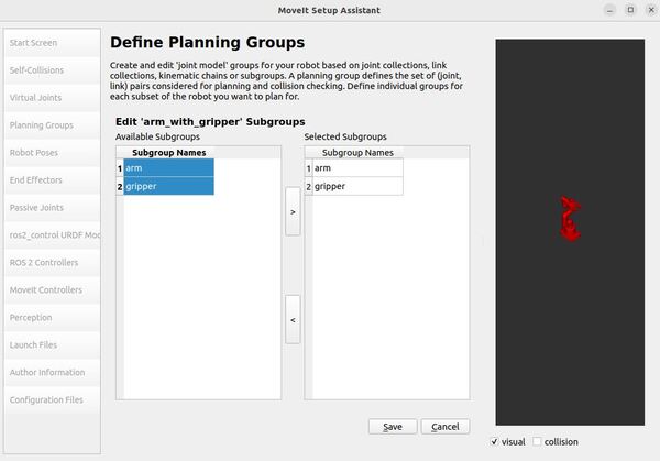
Click the Add Subgroups button.
Select the following subgroups, and click the > button.
- arm
- gripper
Click Save.
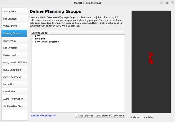
Click Collapse All.
Here is what your screen should look like:
Add Robot Poses
Arm Pose
The Setup Assistant has a useful feature that lets you define and store predefined poses for the robot.
Once these poses are set up, the robot can be instructed to move to these positions using the MoveIt 2 API.
Let’s add a home pose for the arm. Follow these steps…
Click on the Robot Poses pane.
Click the Add Pose button.
Assign a name to the pose, such as “home”.
Initially, the robot will be in its default pose, where all joints are set to their zero values. You can adjust the individual joints to create the desired pose.
For the arm group, define a home pose using the following joint values:
- joint name=”link1_to_link2″ value=”0″
- joint name=”link2_to_link3″ value=”0″
- joint name=”link3_to_link4″ value=”0″
- joint name=”link4_to_link5″ value=”0″
- joint name=”link5_to_link6″ value=”0″
- joint name=”link6_to_link6flange” value=”0″
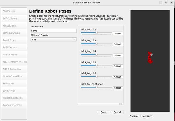
Click the “Save” button to store it.
Remember that poses are linked to specific groups. You have the ability to save separate poses for each group.
Make sure to experiment with moving all the joints. If there are any issues with the joint limits defined in your URDF, you will be able to identify them at this stage of the process.
If you find that you move your robotic arm into positions where the assistant is telling you a collision will occur, go back to the Self-Collisions panel and check that link pair.
Gripper Pose
Now to the gripper. Let’s add an open, half-closed, and closed pose for the gripper.
Follow these steps…
Click on the Robot Poses pane.
Click the Add Pose button.
Assign the name “open” to the pose.
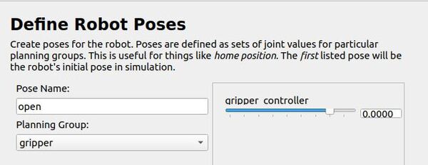
For the gripper group, define an open pose using the following joint value:
- joint name=”gripper_controller” value=”0.0000″
Click the “Save” button to store it.
Click the Add Pose button.
Assign the name “half_closed” to the pose.
For the gripper group, define a close pose using the following joint value:
- joint name=”gripper_controller” value=”-0.36″
Click the “Save” button to store it.
You will notice that only the gripper_controller appears in the list. The reason for this is that all the other gripper joints mimic the gripper_controller.
Click on the Robot Poses pane.
Click the Add Pose button.
Assign the name “closed” to the pose.
For the gripper group, define a closed pose using the following joint value:
- joint name=”gripper_controller” value=”-0.59″
Click the “Save” button to store it.
Click the Add Pose button.
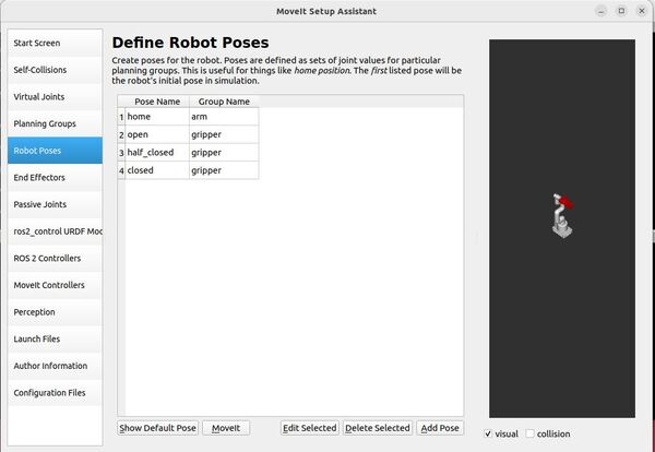
Let’s take a look now at what robot poses we have so far.
Arm with Gripper Pose
Now let’s define a pose for the combined arm_with_gripper group.
Click on the Robot Poses pane.
Click the Add Pose button.
Assign the name “ready” to the pose.
For the arm_with_gripper group, define a pose using the following joint values:
- joint name=”link1_to_link2″ value=”0″
- joint name=”link2_to_link3″ value=”0″
- joint name=”link3_to_link4″ value=”1.5708″
- joint name=”link4_to_link5″ value=”1.5708″
- joint name=”link5_to_link6″ value=”0″
- joint name=”link6_to_link6flange” value=”0″
- joint name=”gripper_controller” value=”0″
Click the “Save” button to store it.
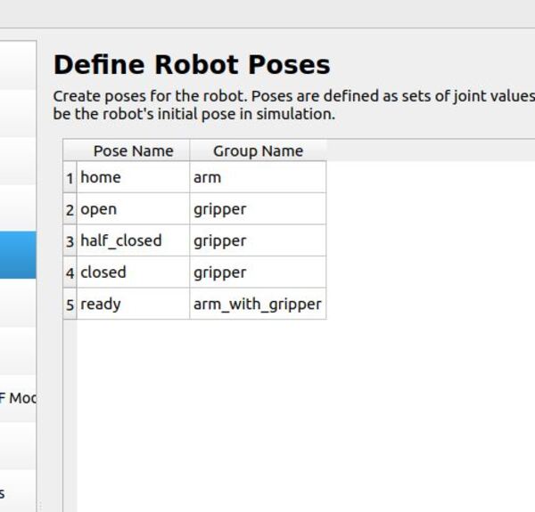
Let’s take a look now at what robot poses we have now.
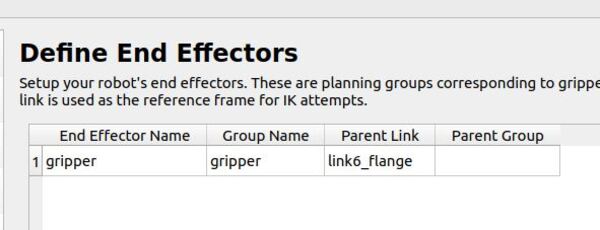
Label End Effectors
Since we have added the gripper as a move group, we can set it as an end effector. By making a group an end effector, MoveIt can do special things with the group. For example, you can attach objects to the arm when doing pick-and-place tasks.
Click on the End Effectors pane.
Click Add End Effector.
Choose gripper as the End Effector Name for the gripper.
Select gripper as the End Effector Group.
Select link6_flange as the Parent Link for this end-effector.
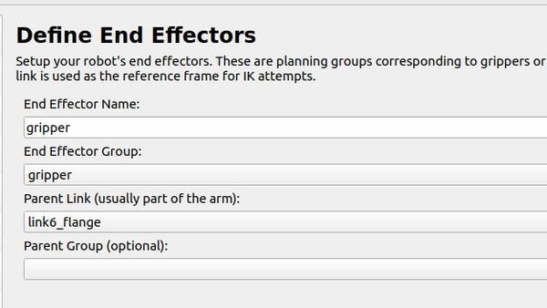
Leave the Parent Group field blank.
Add Passive Joints
Click the Passive Joints pane.
Here we have a section called “Passive Joints.” This is where you tell the software about any parts of your robotic arm that can move but can’t be controlled directly. Think of these like loose joints or hinges that swing freely.
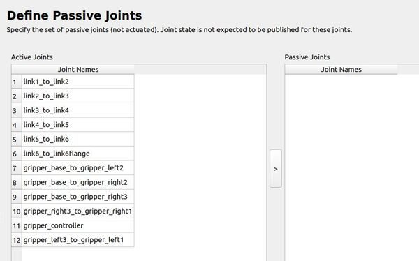
It is important to list these passive joints because the robot’s movement planning software needs to know about them. If it doesn’t, it might try to make plans that involve moving these parts in ways they can’t actually move, which would mess up the whole plan.
In the case of the myCobot 280, it doesn’t have any of these passive joints, so you can skip this part when setting it up.
ros2_control URDF Modification
This step prepares your robot’s URDF file for use with ROS 2’s control system. It adds information about how to command each joint and what information we can get from them.
Since our robot’s URDF file already includes this information (mycobot_280_ros2_control.xacro), you can skip this step.
For each joint in your robot, this step will add:
command_interface:
- The type of commands that can be sent to each joint.
- Position is the default command interface.
- Position:
- For revolute (rotating) joints, units are in radians
- For prismatic (sliding) joints, units are in meters
state_interface:
- The type of information that can be received from each joint.
- Position and velocity are the default state interfaces.
- Position:
- For revolute joints, units are in radians
- For prismatic joints, units are in meters
- Velocity:
- For revolute joints, units are in radians per second
- For prismatic joints, units are in meters per second
If you want to add other command and state interfaces, choose your desired command or state interfaces for the joints on your robot, and then click “Add Interfaces.”
ROS 2 Controllers
This pane allows you to automatically create simulated controllers. These controllers are used to move (or “actuate”) the joints of your robot in a simulated environment.
Click on the ROS 2 Controllers pane selector.
Click Add Controller.
Let’s add the arm joint trajectory controller.
Enter Controller Name as arm_controller.
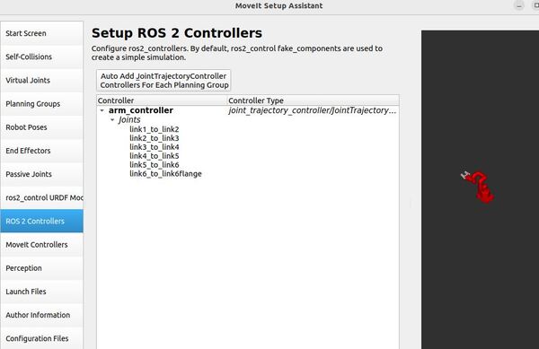
Choose joint_trajectory_controller/JointTrajectoryController as the controller type.
The joint trajectory controller is responsible for generating smooth motions of multiple joints over time.
- Input: A series of joint positions at specific points in time (a trajectory)
- Output: Commands to move joints to follow this trajectory
Now click Add Planning Group Joints.
Choose the arm group from the Available Group tab, and add it to the Selected Groups.
Click Save to save this controller.
Now let’s add the gripper position controller.
Click on the ROS 2 Controllers pane selector.
Click Add Controller again.
Enter Controller Name as grip_action_controller.
Choose position_controllers/GripperActionController as the controller type.
Now click Add Planning Group Joints.
Choose the gripper group from the Available Group tab, and add it to the Selected Groups.
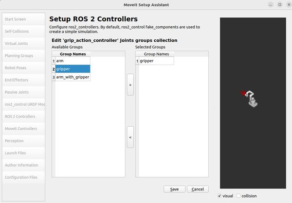
Click Save to save this controller.
MoveIt Controllers
Now click the MoveIt Controllers tab.
MoveIt Controllers are like translators that MoveIt uses to communicate with your robot. They don’t do the actual controlling. ROS 2 Controllers (like Joint Trajectory Controller) are the ones that actually make the robot move by sending signals to its motors.
In practice:
- MoveIt plans a motion.
- The MoveIt Controller takes this plan and formats it for your robot.
- It sends this formatted plan to the appropriate ROS 2 Controller (e.g., Joint Trajectory Controller) via the FollowJointTrajectoryAction interface.
- The ROS 2 Controller then executes this plan by directly controlling the robot’s motors via the ROS 2 Control Hardware Interface.
This separation allows MoveIt to work with many different types of robots and control systems, while the ROS 2 Controllers handle the specifics of how each robot actually moves.
First let’s add the arm MoveIt controllers.
Click on Add Controller to create a new arm controller.
Enter the Controller Name. This name must match the ROS 2 Controller name, which is arm_controller.
Choose FollowJointTrajectory as the Controller Type.
Click Add Planning Group Joints.
Select the arm group under Group Names and then press the > button to push it over to Selected Groups.
Click Save.
Now let’s add the gripper MoveIt controller.
Click on Add Controller to create a new controller.
Enter Controller Name as grip_action_controller.
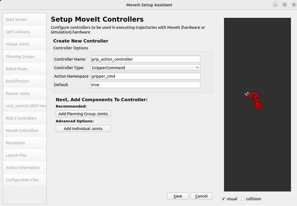
Choose GripperCommand Controller Type.
Click Add Planning Group Joints.
Choose the controller joints with the gripper planning group.
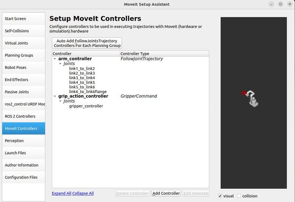
Save the controller.
Here is what everything looks like now.
Perception
Now let’s go to the Perception tab. This tab is where you will configure the settings for your depth camera. These settings will go inside a YAML configuration file called sensors_3d.yaml.
You can see the description of these settings on this page.
Let’s imagine we have an Intel RealSense depth camera.
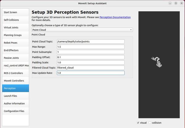
Select Point Cloud from the dropdown menu.
For Point Cloud Topic, select: /camera/depth/color/points
This is the topic that our camera will publish the 3D point cloud to.
For Max Range, put 1.5.
Points further than 1.5 meters will not be used.
For Point Subsample, put 1.
The point_subsample parameter controls how many points are used from a 3D point cloud. It lets you reduce the density of points by only using every nth point, where n is the value of point_subsample. This allows you to balance between having detailed information and faster processing times, depending on your specific needs.
A point_subsample of 1 means you use every point from the point cloud.
For Padding Offset, put 0.1 (units are centimeters).
For robotic arms, padding offset means:
- The arm treats objects as slightly larger than they actually are.
- This extra “cushion” helps prevent the arm from accidentally bumping into things.
- It allows the arm to plan safer movements, especially in tight spaces or when working close to objects.
For the Padding Scale, put 1.0.
Padding scale determines how much the virtual “cushion” around objects grows based on their size. A larger padding scale means bigger objects get proportionally more padding than smaller ones. This allows the robot to adjust its safety margin based on the size of objects it’s working around, potentially being more cautious around larger items.
For the Filtered Cloud Topic, put filtered_cloud.
This topic is used for debugging. It is the filtered point cloud that is produced after it is processed with the parameters we set above.
For Max Update Rate, let’s put 1.0. We can always increase this value later after testing.
This max update rate indicates the number of times per second the system will refresh or update its understanding of the environment around the robot.
Launch Files
Click the Launch Files pane.
Here is a default list of launch files that the MoveIt Setup Assistant will generate. You can keep the defaults.
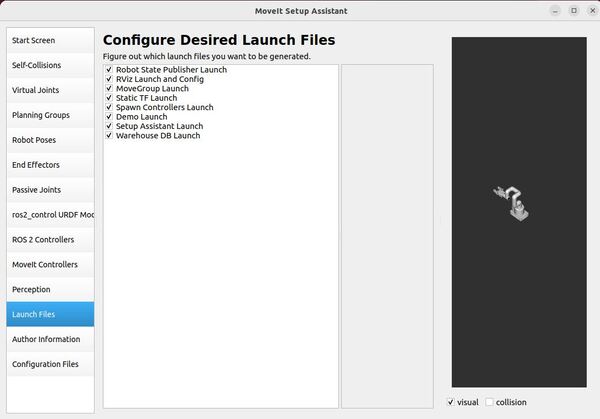
Here is a brief description of what each launch file does:
- Robot State Publisher Launch: Publishes the robot description and transforms generated by the joint states.
- RViz Launch and Config: Configures and launches RViz for visualizing the robot model and its planned movements.
- MoveGroup Launch: Launches the MoveIt! MoveGroup node for motion planning.
- Static TF Launch: Broadcasts static transforms needed for the robot model.
- Spawn Controllers Launch: Launches and configures the robot’s controllers.
- Demo Launch: Provides a sample launch file for demonstrating basic functionalities.
- Setup Assistant Launch: Launches the MoveIt! Setup Assistant for configuring the robot.
- Warehouse DB Launch: Launches the database used for storing complete planning scenes and robot states.
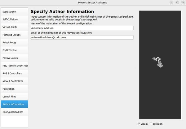
Add Author Information
Click on the Author Information pane.
Add your name and email address if you like.
Generate Configuration Files
Now let’s generate the configuration files you will need to launch MoveIt.
Click on the Configuration Files pane.
Write a location and a name for the ROS 2 package. I will write this in the line:
/home/ubuntu/ros2_ws/src/mycobot_ros2/mycobot_moveit_config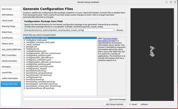
Click the Generate Package button.
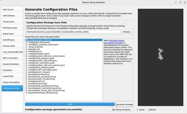
Go into the package and have a look at the configuration files. To understand more about each configuration file, check out this link.
Click Exit Setup Assistant to close the MoveIt Setup Assistant.
You can take a look at all your new files now:
cd /home/ubuntu/ros2_ws/src/mycobot_ros2/mycobot_moveit_configBuild the Workspace
cd ~/ros2_ws/colcon build --packages-select mycobot_moveit_configsource ~/.bashrc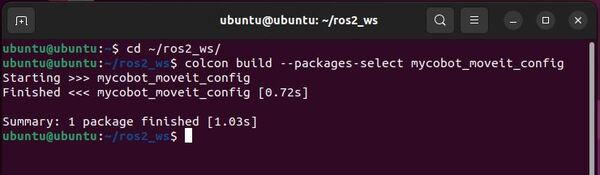
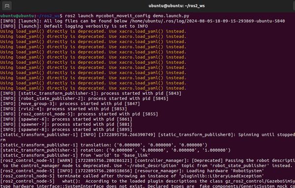
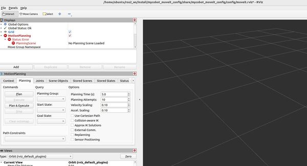
Launching the Demo
You can now try launching the demo, but you will likely get absolutely no output. I got a lot of warnings and depreciation errors and controllers not loading. Such is life with open source software.
ros2 launch mycobot_moveit_config demo.launch.py