How to Set Up the MoveIt 2 Task Constructor – ROS 2 Lyrical

In this tutorial, I will guide you through the core concepts of the MoveIt Task Constructor for ROS 2. You will also install it on your computer.

The MoveIt 2 Task Constructor (MTC) is designed to make complex robot tasks easier to program and manage. 

At its core, the Task Constructor breaks big tasks into smaller, more manageable pieces called stages. These stages can be mixed and matched like building blocks. They can also share information with each other, making it easier to create smooth, coordinated robot actions.

Overall, the goal of the MTC is to give robot programmers a set of tools that make their job more efficient and help them create more reliable and adaptable robot behaviors.

Prerequisites

We will just focus on concepts in this tutorial. In future tutorials, you will learn how to build your own applications using the MTC. You can check out my sample code here on GitHub. Don’t worry. I will go through all that in a later tutorial.

MTC Core Concepts

The MoveIt Task Constructor (MTC) is built around three core concepts that work together in harmony to create a comprehensive system for robot task planning.

Task

A Task is like a big plan for a robot. It is made up of a series of smaller steps that the robot needs to do to complete a job. 

Think of a task as a recipe for the robot to follow. Each Task is built from a sequence of Stages, which are the individual steps or actions the robot needs to take.

Stage

A Stage is a single step within a Task. It is a specific action or calculation the robot needs to perform. 

For example, a Stage might be “move the arm to a certain position” or “open the gripper.” 

Stages can be simple or complex, and they work together to form the complete Task. 

Each Stage produces what’s called a SubSolution, which is the result of that particular step.

Planning Scene

In the previous tutorial, you had experience adding a collision object to the planning scene.

The Planning Scene is the virtual model of the robot’s world. It includes information about the robot itself, any objects in its environment, and any constraints or rules the robot needs to follow. 

When the robot is planning its movements or actions, MoveIt uses this Planning Scene to figure out what the robot can and cannot do. 

The Planning Scene gets updated as the robot moves through its Task, keeping track of changes in the environment.

Stage Types

Let’s take a closer look at stages in the MTC

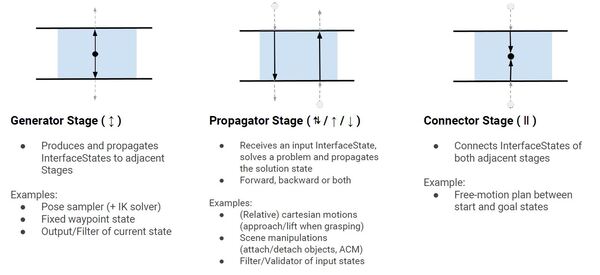
The MTC uses different types of Stages to handle various aspects of task planning. These Stage types are designed to work together, providing a versatile toolkit for creating complex robot behaviors. The three main types of Stages in the MTC are Generator Stage, Propagator Stage, and Connector Stage. 
1-stage-types

Source: PickNik Inc.

Generator Stage

An MTC task starts with a Generator stage. This stage receives no input from adjacent stages. It doesn’t care what happens before it or after it.

The results that are computed in this stage are passed forward and backward.

Let’s look at some examples of Generator Stage types.

Examples

CurrentState is the most important generator stage. This is like taking a snapshot of where the robot is right now. It captures the robot’s current position, the state of its joints, and any objects it might be holding or interacting with. 

CurrentState generates the starting point for planning what the robot will do next.

GeneratePose is another type of generator stage. GeneratePose is about coming up with possible positions for the robot’s arm or gripper. 

For example, if the robot needs to pick up an object, GeneratePose might generate different ways the gripper could be positioned to grab the object. It’s like brainstorming potential positions for the robot.

Propagator Stage

A propagator stage is like a one way street. It receives an input from an adjacent stage, processes that input, and then generates an output for the next stage.

Examples

MoveTo is a propagating stage type because it takes the robot arm’s current state as input and produces a new state as output. 

For example, the MoveTo stage might start with the arm at rest and end with the arm reaching into a parts bin. 

MoveRelative is another propagating stage type because it advances the robot’s state incrementally. It takes the current arm position as input and outputs a new position based on a relative movement. 

For example, during the MoveRelative stage, the arm might move 10cm upward relative to where it currently is in the world, propagating the state forward by this small, relative change.

ModifyPlanningScene takes the current planning scene (the virtual model of the robot’s environment) as input, along with pre-programmed instructions for how to modify that scene (e.g. add or remove objects from the virtual environment). It then outputs an updated planning scene.

Connector Stage (i.e. Connectors)

Unlike Propagators, Connectors do not send results to other stages. Instead, they are like bridges that plan movements between two different arbitrary stages.

An example of a Connector Stage is finding a way to move the arm from its current position to a specific point.

Bringing It All Together

The three stage classes we mentioned above are called “primitive” stage classes. They are the basic building blocks for tasks in MoveIt 2.

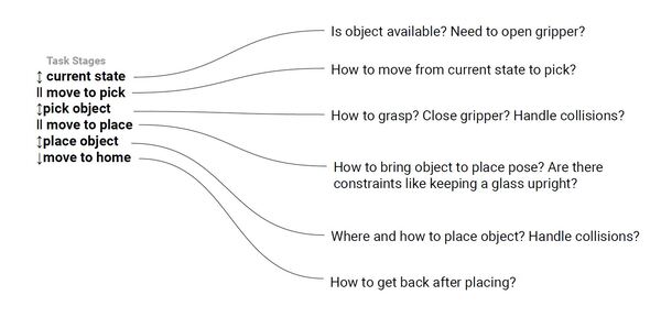
Below is an example of how the stages might be structured for a sample pick and place task. The arrow and bar symbols represent the different stage types.
2-example-stages

Source: PickNik Inc.

Generator Stage (↕️):

  • This stage creates new possibilities.
  • It is like coming up with ideas for the robot to try.
  • Examples: Figuring out different poses the robot could use, or setting a specific position for the robot.

Propagator Stage (↓ or ↑ or both):

  • This stage takes an input and figures out what to do next.
  • It can work forward (↓), backward (↑), or both ways.
  • Examples: Planning how to move in a straight line, or checking if a movement is safe.

Connector Stage (||):

  • This stage links two different states or positions.
  • It’s like finding a path between where the robot is and where it needs to go.
  • Example: Planning how to move freely from a starting position to an end position.

So there you have it. Stages either generate, propagate, or connect.

Containers (grouping primitive stages to perform a task)

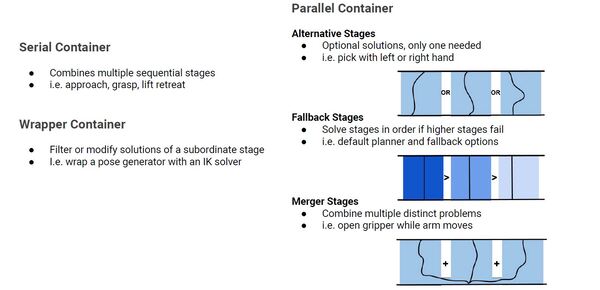
MoveIt Task Constructor (MTC) has a concept called Containers. A Container is like a box that can hold one or more stages or even other containers. It helps group related stages together and create a hierarchy or structure for complex tasks. 

There are three types of container stages: wrapper, serial, and parallel. Let’s go through each one.
3-containers

Source: PickNik Inc.

Wrapper Container

This container is used to modify or filter the solutions of a stage it contains. The wrapper modifies how a single task is performed without changing the core action.

Example: Wrap a pose generator with an IK (Inverse Kinematics) solver

  • A pose generator is a component that comes up with possible positions and orientations for the robot’s end-effector (like its hand or gripper) to grasp an object.
  • An IK (Inverse Kinematics) solver figures out how the robot’s joints should be positioned to achieve the specific end-effector (gripper) pose calculated in #1.
  • By wrapping the pose generator in step #1 with an IK solver in step #2, you’re creating a system that not only generates potential grasping poses but also immediately checks if the robot can actually achieve those poses, ensuring that only reachable and feasible grasping positions are considered.

Serial Containers

This container contains a sequence of stages that must be followed in order. 

Example:

  1. Approach the object (stage 1 – propagator)
  2. Generate the grasp pose (stage 2 – generator)
  3. Grasp the object (stage 3 – propagator)
  4. Lift the object (stage 4 – propagator)

The robot needs to complete all these steps in sequence to successfully complete the task.

Parallel Containers

This container allows for the simultaneous or alternative execution of multiple stages. It can include:

  • Alternative Stages:
    • Alternative Stages are different options to achieve the same goal, where only one needs to succeed. 
    • For example, you might have stages for picking an object with either the left hand or the right hand. The task will be successful if the robot can pick with either hand.
  • Fallback Stages:
    • Fallback Stages are backup options that are tried in order if earlier ones fail. For instance, you might have a default motion planner, and if that doesn’t work, it will try alternative planners. This ensures that even if the preferred method fails, there are other ways to complete the task.
  • Merger Stages:
    • Merger Stages allow multiple distinct actions to happen at the same time. 
    • For example, the robot could open its gripper while simultaneously moving its arm to a new position. This can make tasks more efficient by combining compatible actions.

Parallel Containers give flexibility in how tasks are performed, allowing for multiple approaches, backup plans, and simultaneous actions. This makes robotic tasks more adaptable and robust.

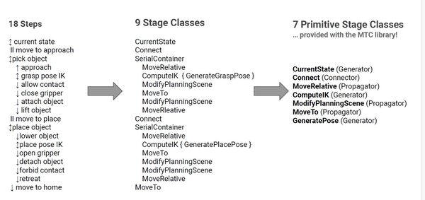
Example: Pick and Place

Have a look at this diagram and see how containers and stage types could be organized in a sample pick and place application.
4-have-a-look-pick-place

Source: PickNik Inc.

That covers the basic concepts of the MTC.

If you want to do further reading, check out this link at the official MoveIt 2 website.

Create a New Package

Let’s start our hands-on experience by creating a new package for our MoveIt 2 Task Constructor (MTC) code. Open a terminal and navigate to the mycobot_ros2 directory in your ROS 2 workspace:

cd ~/ros2_ws/src/mycobot_ros2/

Now, let’s create a new package using the ROS 2 command line tools:

ros2 pkg create --build-type ament_cmake \
--dependencies generate_parameter_library moveit_core moveit_ros_planning_interface rclcpp \
--license BSD-3-Clause \
--maintainer-name ubuntu \
--maintainer-email automaticaddison@todo.com \
--node-name alternative_path_costs \
mycobot_mtc_demos
cd ~/ros2_ws/
rosdep install --from-paths src --ignore-src -r -y

Type in your password, and install any missing dependencies.

Now build.

colcon build && source ~/.bashrc

Install the MoveIt Task Constructor

This part used to be a long slog. On Lyrical it is one command.

Open a terminal window, and type:

sudo apt-get install -y ros-${ROS_DISTRO}-moveit-task-constructor-core ros-${ROS_DISTRO}-moveit-task-constructor-msgs ros-${ROS_DISTRO}-moveit-task-constructor-visualization

That is the whole install. The MoveIt Task Constructor is a regular package now, so you no longer download the source, pin it to a commit, build it, and then patch two files by hand to get it working.

If you followed the older version of this tutorial, you may remember installing MongoDB and a package called warehouse_ros_mongo along the way. You can skip all of that. It was only there for a database feature none of these tutorials use, and the library it depended on is not part of Ubuntu 26.04 anymore.

Let’s make sure it worked. Type:

ros2 pkg list | grep moveit_task_constructor

You should see three packages listed: moveit_task_constructor_core, moveit_task_constructor_msgs, and moveit_task_constructor_visualization.

Configure Your MTC Package

Edit package.xml

cd ~/ros2_ws/src/mycobot_ros2/mycobot_mtc_demos/
gedit package.xml

Your dependencies should look like this:

  <depend>generate_parameter_library</depend>
  <depend>moveit_core</depend>
  <depend>moveit_ros_planning_interface</depend>
  <depend>moveit_task_constructor_core</depend>
  <depend>rclcpp</depend>
cd ~/ros2_ws/
rosdep install --from-paths src --ignore-src -r -y

Create a Launch File for the Demos

Move inside the package.

cd ~/ros2_ws/src/mycobot_ros2/mycobot_mtc_demos/

Create a folder named launch.

mkdir launch

Now let’s add a launch file:

cd launch
touch mtc_demos.launch.py

Add this code.

Save the file, and close it.

Create an RViz Config File

cd ~/ros2_ws/src/mycobot_ros2/mycobot_mtc_demos/
mkdir rviz
cd rviz
gedit mtc_demos.rviz

Add this code.

Save the file, and close it.

Edit CMakeLists.txt

Let’s add the new folders.

cd ~/ros2_ws/src/mycobot_ros2/mycobot_mtc_demos

Open CMakeLists.txt.

Add this block:

# Copy necessary files to designated locations in the project
install (
  DIRECTORY launch rviz
  DESTINATION share/${PROJECT_NAME}
)

Add Demonstration Code

cd ~/ros2_ws/src/mycobot_ros2/mycobot_mtc_demos/src/

Add all the files you see in this directory into the src folder.

Edit CMakeLists.txt

Now let’s edit CMakeLists.txt.

cd ~/ros2_ws/src/mycobot_ros2/mycobot_mtc_demos/
gedit CMakeLists.txt

Add this code.

Save the file, and close it.

Build the Package

Now let’s build.

cd ~/ros2_ws/
colcon build
source ~/.bashrc

Add a Quick Launch Script

cd ~/ros2_ws/src/mycobot_ros2/mycobot_bringup/scripts
touch mycobot_280_mtc_demos.sh

Add this placeholder code:

#!/bin/bash
# Single script to launch the mycobot with Gazebo, RViz, and MoveIt 2

cleanup() {
    echo "Cleaning up..."
    sleep 5.0
    pkill -9 -f "ros2|gazebo|gz|nav2|amcl|bt_navigator|nav_to_pose|rviz2|assisted_teleop|cmd_vel_relay|robot_state_publisher|joint_state_publisher|move_to_free|mqtt|autodock|cliff_detection|moveit|move_group|basic_navigator"
}

# Set up cleanup trap
trap 'cleanup' SIGINT SIGTERM

echo "Launching Gazebo simulation..."
ros2 launch mycobot_gazebo mycobot.gazebo.launch.py \
    load_controllers:=true \
    world_file:=pick_and_place_demo.world \
    use_camera:=true \
    use_rviz:=false \
    use_robot_state_pub:=true \
    use_sim_time:=true \
    x:=0.0 \
    y:=0.0 \
    z:=0.05 \
    roll:=0.0 \
    pitch:=0.0 \
    yaw:=0.0 &

sleep 15
ros2 launch mycobot_moveit_config move_group.launch.py \
    rviz_config_file:=mtc_demos.rviz \
    rviz_config_package:=mycobot_mtc_demos &

echo "Adjusting camera position..."
gz service -s /gui/move_to/pose \
    --reqtype gz.msgs.GUICamera \
    --reptype gz.msgs.Boolean \
    --timeout 2000 \
    --req "pose: {position: {x: 1.36, y: -0.58, z: 0.95} orientation: {x: -0.26, y: 0.1, z: 0.89, w: 0.35}}"

# Keep the script running until Ctrl+C
wait

Save the file, and close it.

Now add an alias called mtc_demos to your bashrc file:

echo "alias mtc_demos='bash ~/ros2_ws/src/mycobot_ros2/mycobot_bringup/scripts/mycobot_280_mtc_demos.sh'" >> ~/.bashrc && source ~/.bashrc

That’s it! You are now ready to start taking a closer look at the demo applications. We will do just that in the following tutorials. Keep building!
Add and Plan Around Objects Using MoveIt 2 – ROS 2 Lyrical

In this tutorial, we will build upon our previous “Hello World” project to learn how to plan around objects in a simulated environment using C++ and MoveIt 2. I will guide you through the process of inserting collision objects into the planning scene and programming the robot to plan its movements while avoiding these obstacles.

The official instructions for this tutorial are available on the MoveIt 2 website, but we’ll walk through everything together, step by step. We’ll cover how to create and add collision objects to the scene, update target poses, and use the Planning Scene Interface to communicate changes to MoveGroup.

By the end of this tutorial, you will be able to create a program that allows a robot to plan and execute movements while avoiding obstacles in its environment. The result will look something like this:

planning-around-objects-moveit

Prerequisites

All my code for this project is located here on GitHub.

Add moveit_visual_tools as a Dependency

First let’s add moveit_visual_tools as a dependency inside the mycobot_moveit_demos package.

The moveit_visual_tools package is a visualization toolkit for MoveIt that provides tools to visualize robot states, trajectories, collision objects, and planning scenes in ROS 2. It integrates with RViz and is particularly useful for debugging motion planning issues, offering functions to generate markers, display text, and visualize trajectories in the 3D environment.

Open a terminal window, and type:

cd ~/ros2_ws/src/mycobot_ros2/mycobot_moveit_demos/
gedit package.xml

Add this dependency:

<depend>moveit_visual_tools</depend>

Save the file, and close it.

gedit CMakeLists.txt

Add this:

find_package(moveit_visual_tools REQUIRED)

Save the file, and close it.

Now let’s build the package.

cd ~/ros2_ws/
rosdep install --from-paths src --ignore-src -y

You will see a prompt to install moveit-visual-tools.

Type your password, and press Enter.

colcon build
source ~/.bashrc

Create a New File

We’ll start our tutorial by creating a new C++ source file in the appropriate directory of our ROS 2 workspace. Here’s how to do it…

Open a terminal window on your computer. Navigate to the correct directory in your ROS 2 workspace by entering this command:

cd ~/ros2_ws/src/mycobot_ros2/mycobot_moveit_demos/src

Now that we’re in the right location, let’s create our new file. We’ll name it “plan_around_objects.cpp”. You can create this file using a text editor of your choice. For example, if you’re using the gedit text editor, you would type:

touch plan_around_objects.cpp

With our new file open, add this code:

/**
 * @file plan_around_objects.cpp
 * @brief Demonstrates basic usage of MoveIt with ROS 2 and collision avoidance.
 *
 * This program initializes a ROS 2 node, sets up a MoveIt interface for a robot manipulator,
 * creates a collision object in the scene, plans a motion to a target pose while avoiding
 * the collision object, and executes the planned motion.
 *
 * @author Addison Sears-Collins
 * @date August 26, 2026
 */

#include <moveit/move_group_interface/move_group_interface.hpp>
#include <moveit/planning_scene_interface/planning_scene_interface.hpp>
#include <moveit_visual_tools/moveit_visual_tools.h>

#include <geometry_msgs/msg/pose_stamped.hpp>

#include <memory>
#include <rclcpp/rclcpp.hpp>
#include <thread>

/**
 * @brief The main function that starts our program.
 *
 * This function sets up our ROS 2 environment and prepares it for robot control.
 *
 * @param argc The number of input arguments our program receives.
 * @param argv The list of input arguments our program receives.
 * @return int A number indicating if our program finished successfully (0) or not.
 */
int main(int argc, char * argv[])
{
  // Start up ROS 2
  rclcpp::init(argc, argv);

  // Creates a node named "plan_around_objects". The node is set up to automatically
  // handle any settings (parameters) we might want to change later without editing the code.
  auto const node = std::make_shared<rclcpp::Node>(
    "plan_around_objects",
    rclcpp::NodeOptions().automatically_declare_parameters_from_overrides(true)
  );

  // Creates a "logger" that we can use to print out information or error messages
  // as our program runs.
  auto const logger = rclcpp::get_logger("plan_around_objects");

  // This code creates a separate thread, which is like a mini-program running alongside our main program.
  // This thread uses a ROS 2 "executor" to continuously process information about the robot's state.
  // By running this in its own thread, our ROS 2 node can keep getting updates about the robot without
  // interrupting the main flow of our program.
  rclcpp::executors::SingleThreadedExecutor executor;
  executor.add_node(node);
  auto spinner = std::thread([&executor]() { executor.spin(); });

  // Create the MoveIt MoveGroup Interfaces
  // These interfaces are used to plan and execute movements, set target poses,
  // and perform other motion-related tasks for each respective part of the robot.
  // The use of auto allows the compiler to automatically deduce the type of variable.
  // Source: https://github.com/moveit/moveit2/blob/main/moveit_ros/planning_interface/move_group_interface/include/moveit/move_group_interface/move_group_interface.h
  using moveit::planning_interface::MoveGroupInterface;
  auto arm_group_interface = MoveGroupInterface(node, "arm");

  // Specify a planning pipeline to be used for further planning
  arm_group_interface.setPlanningPipelineId("ompl");

  // Specify a planner to be used for further planning
  arm_group_interface.setPlannerId("RRTConnectkConfigDefault");

  // Specify the maximum amount of time in seconds to use when planning
  arm_group_interface.setPlanningTime(1.0);

  // Set a scaling factor for optionally reducing the maximum joint velocity. Allowed values are in (0,1].
  arm_group_interface.setMaxVelocityScalingFactor(1.0);

  //  Set a scaling factor for optionally reducing the maximum joint acceleration. Allowed values are in (0,1].
  arm_group_interface.setMaxAccelerationScalingFactor(1.0);

  // Display helpful logging messages on the terminal
  RCLCPP_INFO(logger, "Planning pipeline: %s", arm_group_interface.getPlanningPipelineId().c_str());
  RCLCPP_INFO(logger, "Planner ID: %s", arm_group_interface.getPlannerId().c_str());
  RCLCPP_INFO(logger, "Planning time: %.2f", arm_group_interface.getPlanningTime());

  // Construct and initialize MoveItVisualTools
  auto moveit_visual_tools =
      moveit_visual_tools::MoveItVisualTools{ node, "base_link", rviz_visual_tools::RVIZ_MARKER_TOPIC,
                                              arm_group_interface.getRobotModel() };

  // Erase all existing visual markers from the RViz visualization.
  moveit_visual_tools.deleteAllMarkers();

  // Load the remote control interface for MoveIt visual tools.
  moveit_visual_tools.loadRemoteControl();

  // Lambda function to draw a title in the RViz visualization
  auto const draw_title = [&moveit_visual_tools](auto text) {
    // Nested lambda to create a pose for the text
    auto const text_pose = [] {
        // Create an identity transform
        auto msg = Eigen::Isometry3d::Identity();
        // Set the z-coordinate to 1.0 (1 meter above the origin)
        msg.translation().z() = 1.0;
        return msg;
    }();

    // Publish the text to RViz
    // Parameters: pose, text content, color (WHITE), and size (XLARGE)
    moveit_visual_tools.publishText(text_pose, text, rviz_visual_tools::WHITE, rviz_visual_tools::XLARGE);
  };

  // Lambda function to display a prompt message in RViz
  auto const prompt = [&moveit_visual_tools](auto text) {
    moveit_visual_tools.prompt(text);
  };

  // Lambda function to visualize a trajectory as a line in RViz
  auto const draw_trajectory_tool_path =
    [&moveit_visual_tools, jmg = arm_group_interface.getRobotModel()->getJointModelGroup("arm")](
	  auto const trajectory) {moveit_visual_tools.publishTrajectoryLine(trajectory, jmg);};

  // Set a target pose for the end effector of the arm
  auto const arm_target_pose = [&node]{
    geometry_msgs::msg::PoseStamped msg;
    msg.header.frame_id = "base_link";
    msg.header.stamp = node->now();
    msg.pose.position.x = 0.128;
    msg.pose.position.y = -0.266;
    msg.pose.position.z = 0.111;
    msg.pose.orientation.x = 0.635;
    msg.pose.orientation.y = -0.268;
    msg.pose.orientation.z = 0.694;
    msg.pose.orientation.w = 0.206;
    return msg;
  }();
  arm_group_interface.setPoseTarget(arm_target_pose);

  // Create collision object for the robot to avoid
  auto const collision_object = [frame_id = arm_group_interface.getPlanningFrame(), &node, &logger] {

    // Print the planning frame for debugging purposes
    RCLCPP_INFO(logger, "Planning frame: %s", frame_id.c_str());

    // Initialize a CollisionObject message
    moveit_msgs::msg::CollisionObject collision_object;

    // Set the frame ID for the collision object
    collision_object.header.frame_id = frame_id;

    // Set the timestamp to the current time
    collision_object.header.stamp = node->now();

    // Assign a unique ID to the collision object
    collision_object.id = "box1";

    // Define the shape of the collision object as a box
    shape_msgs::msg::SolidPrimitive primitive;
    primitive.type = primitive.BOX;
    primitive.dimensions.resize(3);

    // Set the dimensions of the box (in meters)
    primitive.dimensions[primitive.BOX_X] = 0.2;  // Width
    primitive.dimensions[primitive.BOX_Y] = 0.05;  // Depth
    primitive.dimensions[primitive.BOX_Z] = 0.50;  // Height

    // Define the pose (position and orientation) of the box
    geometry_msgs::msg::Pose box_pose;

    // Set the position of the box center
    box_pose.position.x = 0.22;  // meters in x-direction
    box_pose.position.y = 0.0;   // Centered in y-direction
    box_pose.position.z = 0.25;  // meters in z-direction

    // Set the orientation of the box (no rotation in this case)
    box_pose.orientation.x = 0.0;
    box_pose.orientation.y = 0.0;
    box_pose.orientation.z = 0.0;
    box_pose.orientation.w = 1.0;

    // Add the shape and pose to the collision object
    collision_object.primitives.push_back(primitive);
    collision_object.primitive_poses.push_back(box_pose);

    // Set the operation to add the object to the planning scene
    collision_object.operation = collision_object.ADD;

    // Log information about the created collision object
    RCLCPP_INFO(logger, "Created collision object: %s", collision_object.id.c_str());

    RCLCPP_INFO(logger, "Box dimensions: %.2f x %.2f x %.2f",
      primitive.dimensions[primitive.BOX_X],
      primitive.dimensions[primitive.BOX_Y],
      primitive.dimensions[primitive.BOX_Z]);

    RCLCPP_INFO(logger, "Box position: (%.2f, %.2f, %.2f)",
      box_pose.position.x, box_pose.position.y, box_pose.position.z);

    // Return the fully defined collision object
    return collision_object;
  }();

  // Set up a virtual representation of the robot's environment
  moveit::planning_interface::PlanningSceneInterface planning_scene_interface;

  // Add an object to this virtual environment that the robot needs to avoid colliding with
  planning_scene_interface.applyCollisionObject(collision_object);

  // Ask the user to press 'next' to continue
  prompt("Press 'next' in the RvizVisualToolsGui window to plan");

  // Set up a title for the next visualization step
  draw_title("Planning");

  // Update the visualization to show the new title and wait for user input
  moveit_visual_tools.trigger();

  // Create a plan to that target pose
  // This will give us two things:
  // 1. Whether the planning was successful (stored in 'success')
  // 2. The actual motion plan (stored in 'plan')
  auto const [success, plan] = [&arm_group_interface] {
    moveit::planning_interface::MoveGroupInterface::Plan msg;
    auto const ok = static_cast<bool>(arm_group_interface.plan(msg));
    return std::make_pair(ok, msg);
  }();

  // Try to execute the movement plan if it was created successfully
  // If the plan wasn't successful, report an error
  // Execute the plan
  if (success)
  {
	// Visualize the planned trajectory in RViz
    draw_trajectory_tool_path(plan.trajectory);

    // Trigger the visualization update
    moveit_visual_tools.trigger();

    // Prompt the user to continue to execution
    prompt("Press 'next' in the RvizVisualToolsGui window to execute");

    // Update the title in RViz to show we're executing the plan
    draw_title("Executing");

    // Trigger another visualization update
    moveit_visual_tools.trigger();

    // Execute the planned motion
    arm_group_interface.execute(plan);
  }
  else
  {
    // If planning failed, update the title in RViz
    draw_title("Planning Failed!");

    // Trigger the visualization update
    moveit_visual_tools.trigger();

    // Log an error message
    RCLCPP_ERROR(logger, "Planning failed!");
  }

  // Clean up and shut down the ROS 2 node
  rclcpp::shutdown();

  // Wait for the spinner thread to finish
  spinner.join();

  // Exit the program
  return 0;
}

Save the file, and close it.

Understanding the Plan Around Objects Code

Let’s walk through the code before we see it in action.

The code starts with some introductory comments explaining what the program does. 

Next, we see a bunch of include statements. These include statements tell the program which tools it needs to use. In this case, it’s bringing in libraries for controlling the robot, planning movements, and visualizing what’s happening.

The main function is where the actual program starts. It begins by initializing ROS 2.

The code sets up a separate thread, which is like a mini-program running alongside our main one. This thread keeps track of what’s happening with the robot in real-time.

Next, it creates interfaces for controlling the robot arm. These interfaces are how our program talks to the robot, telling it where to move and how to plan its movements. The code specifies some settings for these movements, like how fast the arm can move and how long it can take to plan a path.

The program then sets up tools for visualizing what’s happening. This allows us to see a 3D representation of the robot and its planned movements in RViz.

After that, the code specifies a target pose for the robot arm. This is the position and orientation we want the arm to move to.

One of the key parts of this program is creating a virtual obstacle. It defines a box in the robot’s workspace that the arm needs to avoid. This box is given a specific size and position.

With the target and obstacle set up, the program then asks the robot to plan a path to the target that avoids the obstacle. If it successfully creates a plan, it shows this plan in RViz and then tells the robot to execute the movement.

Throughout this process, the code includes various prompts and visual cues to keep you informed about what’s happening. It also has error handling to deal with situations where the robot can’t find a safe path to the target.

Finally, the program cleans up after itself, shutting down ROS 2 and ending the separate thread it created at the beginning.

Understanding Virtual Joints

One more topic before we run our code. Let’s discuss virtual joints. 

If you look at my code, you will see the following call:

arm_group_interface.getPlanningFrame()

This code retrieves the parent frame of the “virtual joint” defined in the SRDF file. In our case, this is the “world” frame.

A virtual joint is like an imaginary connection between your robot and the world around it. It’s not a real, physical joint, but rather a way to tell the robot how it can move in relation to its environment.

Think of it like this: Imagine you have a toy robot on a table. The robot itself can move its arms and legs, but it can also slide around on the table. The sliding motion isn’t due to any actual joint in the robot, but you need a way to describe this movement. That’s where a virtual joint comes in.

For a mobile manipulator, you will often see the following in an SRDF:

<virtual_joint name="virtual_joint" type="planar" parent_frame="odom" child_link="base_footprint" />

odom” is used as the world frame because it represents the robot’s odometry – essentially, its position in the world as the robot understands it based on its movement.

base_footprint” is often chosen as the child link because it represents the base of the robot – imagine the point where the robot touches the ground.

The planar virtual joint tells MoveIt that the robot’s base can move in a plane. It doesn’t actually move the robot, but allows MoveIt to consider the base’s potential positions when planning arm movements.

Also, remember that MoveIt maintains a planning scene that includes the robot’s current state and the environment.

The virtual joint allows the planning scene to be updated with base movements, even though MoveIt isn’t controlling the base directly.

I will also note that for a mobile manipulator, the URDF describes just the physical structure of the robot. It does not include the virtual joint information. The URDF would typically start with the base_footprint link and describe the physical joints and links from there.

The SRDF is where the virtual joint is defined for use with MoveIt. It adds semantic information on top of the URDF, including things like virtual joints, group definitions, and end effectors (i.e. grippers).

Edit CMakeLists.txt

Now let’s build our code.

Open a terminal window, and type:

cd ~/ros2_ws/src/mycobot_ros2/mycobot_moveit_demos/
gedit CMakeLists.txt

Add this code.

Save the file, and close it.

Edit package.xml

Open a terminal window, and type:

cd ~/ros2_ws/src/mycobot_ros2/mycobot_moveit_demos/
gedit package.xml

Add this code.

Save the file, and close it.

Build the Package

cd ~/ros2_ws
colcon build 
source ~/.bashrc

Run the Program

Now that we’ve set up our target pose and added a collision object to the planning scene, it’s time to run our program and see the results.

Launch the robot.

bash ~/ros2_ws/src/mycobot_ros2/mycobot_bringup/scripts/mycobot_280_gazebo_and_moveit.sh

Run your node:

ros2 run mycobot_moveit_demos plan_around_objects

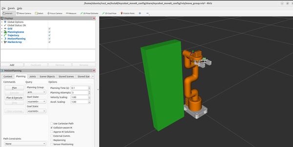
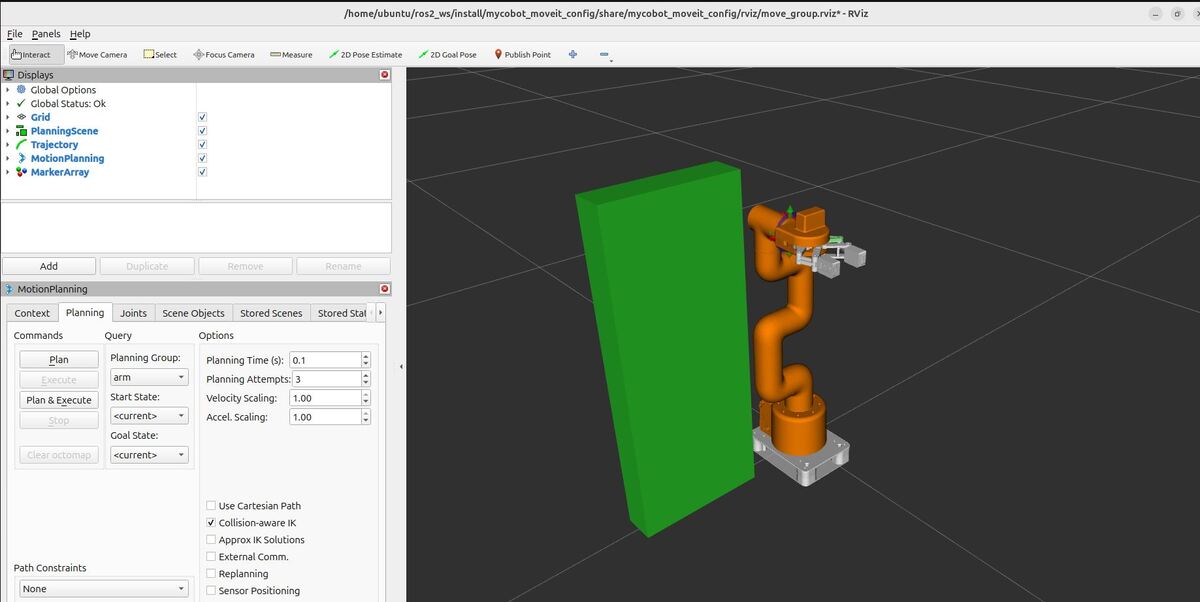
When you run the program, you should observe the following in RViz:

  • The robot model should be visible.
  • A box representing your collision object should appear in the planning scene.
1-planning-around-objects

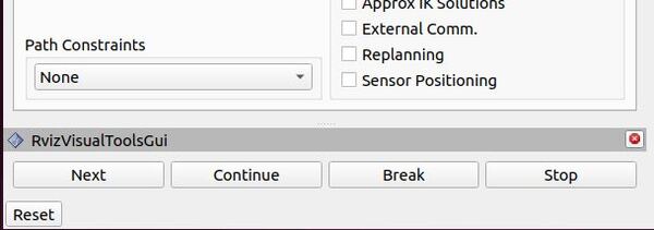
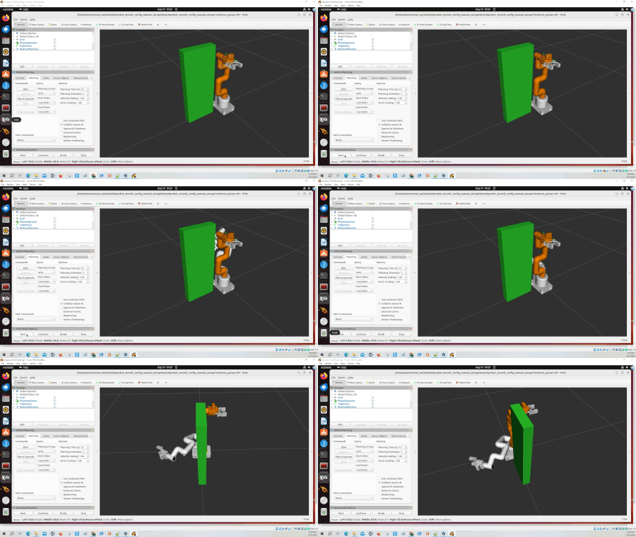
Now click Next under RVizVisualToolsGui on the bottom-left of RViz.

3-click-next

The robot should plan a path to the target pose you specified, avoiding the collision object.

If the planning is successful, you’ll see a visualization of the planned path in RViz. The path should clearly avoid the collision object you added.

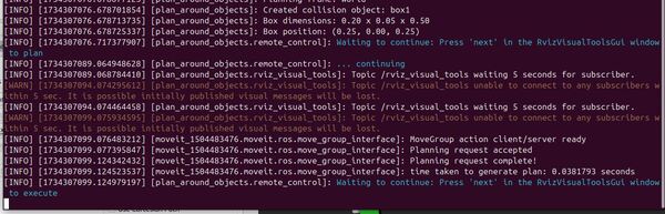
You will also see a “Planning request complete!” message in the logs.

2-planning-complete

If you don’t see the collision object or if the robot’s planned path seems to ignore it, double-check that your collision object’s dimensions and position are appropriate for your robot’s workspace.

Now type Next again to execute.

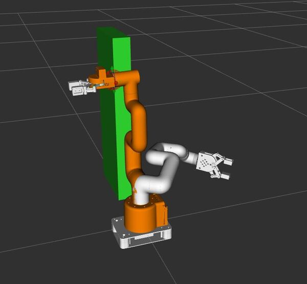
You should see your robot move to the goal.

3-robot-at-the-goal
6-execution-success

That’s it. Keep building!

How to Create Your First C++ MoveIt 2 Project – ROS 2 Lyrical

In this tutorial, we will create a basic “Hello World” project to get your feet wet with C++ and MoveIt 2. I will show you how to move the end of the robotic arm (where the gripper is located) to a desired position and orientation. 

The official instructions are on this page, but we will walk through everything together, step by step.

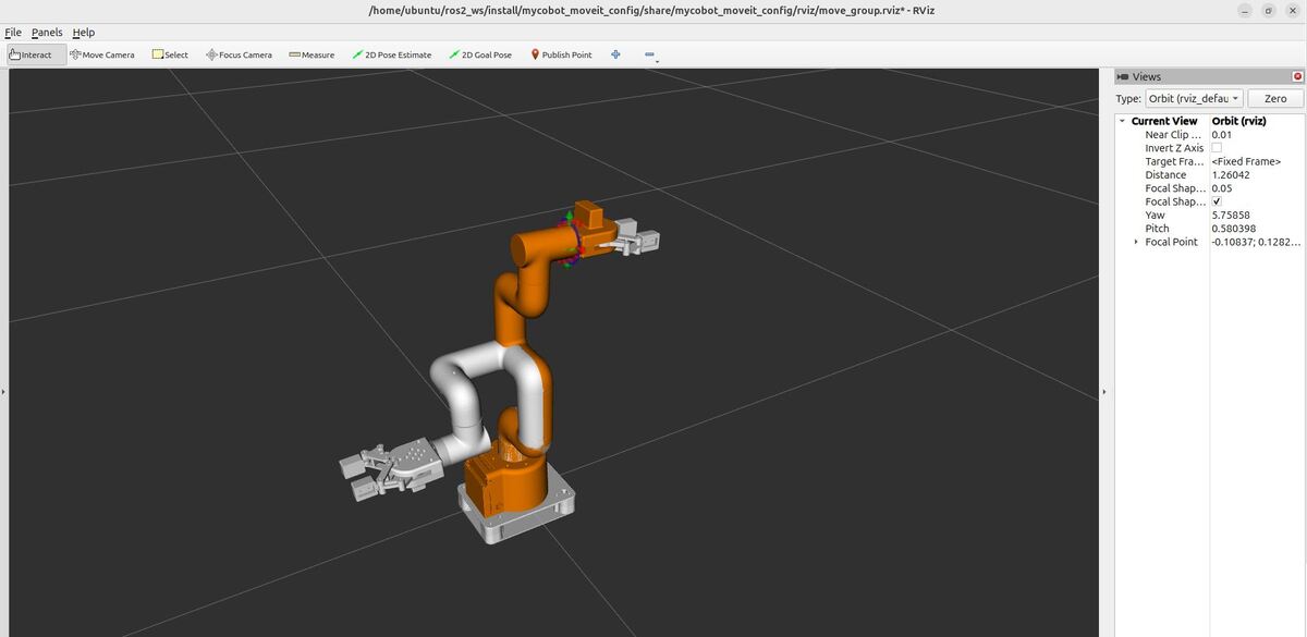
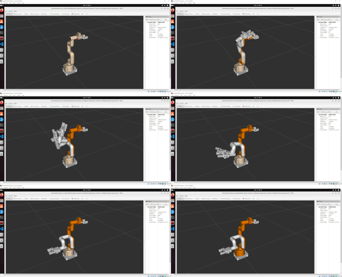
By the end of this tutorial, you will be able to create this:

moveit-cpp-first-program-ros2

Prerequisites

All my code for this project is located here on GitHub.

Create a Package

Let’s start by creating a new package for our project. Open a terminal and navigate to the mycobot_ros2 directory in your ROS 2 workspace:

cd ~/ros2_ws/src/mycobot_ros2/

Now, let’s create a new package using the ROS 2 command line tools:

ros2 pkg create --build-type ament_cmake \
--dependencies moveit_ros_planning_interface rclcpp \
--license BSD-3-Clause \
--maintainer-name ubuntu \
--maintainer-email automaticaddison@todo.com \
--node-name hello_moveit \
mycobot_moveit_demos

This command creates a new package named “mycobot_moveit_demos” with the necessary dependencies and a node named “hello_moveit”. The package will be created inside the mycobot_ros2 directory.

Next, let’s move into our newly created package:

cd mycobot_moveit_demos

Create a ROS Node

Now that we have our package in place, let’s set up our C++ file to work with MoveIt 2. We’ll start by editing the main source file.

Open the new source code file you created.

cd src

Open hello_moveit.cpp.

Add this code:

/**
 * @file hello_moveit.cpp
 * @brief A basic ROS 2 and MoveIt 2 program to control a robot arm
 *
 * This program demonstrates how to use ROS 2 and MoveIt 2 to control a robot arm.
 * It sets up a node, creates a MoveGroupInterface for the arm, sets a target pose for the gripper_base,
 * plans a trajectory, and executes the planned motion.
 *
 * @author Addison Sears-Collins
 * @date August 26, 2026
 */

#include <geometry_msgs/msg/pose_stamped.hpp>
#include <memory>
#include <rclcpp/rclcpp.hpp>
#include <moveit/move_group_interface/move_group_interface.hpp>

/**
 * @brief The main function that starts our program.
 *
 * This function sets up our ROS 2 environment and prepares it for robot control.
 *
 * @param argc The number of input arguments our program receives.
 * @param argv The list of input arguments our program receives.
 * @return int A number indicating if our program finished successfully (0) or not.
 */
int main(int argc, char * argv[])
{
  // Start up ROS 2
  rclcpp::init(argc, argv);

  // Creates a node named "hello_moveit". The node is set up to automatically
  // handle any settings (parameters) we might want to change later without editing the code.
  auto const node = std::make_shared<rclcpp::Node>(
    "hello_moveit",
    rclcpp::NodeOptions().automatically_declare_parameters_from_overrides(true)
  );

  // Creates a "logger" that we can use to print out information or error messages
  // as our program runs.
  auto const logger = rclcpp::get_logger("hello_moveit");

  // Create the MoveIt MoveGroup Interfaces
  // These interfaces are used to plan and execute movements, set target poses,
  // and perform other motion-related tasks for each respective part of the robot.
  // The use of auto allows the compiler to automatically deduce the type of variable.
  // Source: https://github.com/moveit/moveit2/blob/main/moveit_ros/planning_interface/move_group_interface/include/moveit/move_group_interface/move_group_interface.h
  using moveit::planning_interface::MoveGroupInterface;
  auto arm_group_interface = MoveGroupInterface(node, "arm");

  // Specify a planning pipeline to be used for further planning
  arm_group_interface.setPlanningPipelineId("ompl");

  // Specify a planner to be used for further planning
  arm_group_interface.setPlannerId("RRTConnectkConfigDefault");

  // Specify the maximum amount of time in seconds to use when planning
  arm_group_interface.setPlanningTime(1.0);

  // Set a scaling factor for optionally reducing the maximum joint velocity. Allowed values are in (0,1].
  arm_group_interface.setMaxVelocityScalingFactor(1.0);

  //  Set a scaling factor for optionally reducing the maximum joint acceleration. Allowed values are in (0,1].
  arm_group_interface.setMaxAccelerationScalingFactor(1.0);

  // Display helpful logging messages on the terminal
  RCLCPP_INFO(logger, "Planning pipeline: %s", arm_group_interface.getPlanningPipelineId().c_str());
  RCLCPP_INFO(logger, "Planner ID: %s", arm_group_interface.getPlannerId().c_str());
  RCLCPP_INFO(logger, "Planning time: %.2f", arm_group_interface.getPlanningTime());

  // Set a target pose for the end effector of the arm
  auto const arm_target_pose = [&node]{
    geometry_msgs::msg::PoseStamped msg;
    msg.header.frame_id = "base_link";
    msg.header.stamp = node->now();
    msg.pose.position.x = 0.061;
    msg.pose.position.y = -0.176;
    msg.pose.position.z = 0.168;
    msg.pose.orientation.x = 1.0;
    msg.pose.orientation.y = 0.0;
    msg.pose.orientation.z = 0.0;
    msg.pose.orientation.w = 0.0;
    return msg;
  }();
  arm_group_interface.setPoseTarget(arm_target_pose);

  // Create a plan to that target pose
  // This will give us two things:
  // 1. Whether the planning was successful (stored in 'success')
  // 2. The actual motion plan (stored in 'plan')
  auto const [success, plan] = [&arm_group_interface] {
    moveit::planning_interface::MoveGroupInterface::Plan msg;
    auto const ok = static_cast<bool>(arm_group_interface.plan(msg));
    return std::make_pair(ok, msg);
  }();

  // Try to execute the movement plan if it was created successfully
  // If the plan wasn't successful, report an error
  // Execute the plan
  if (success)
  {
    arm_group_interface.execute(plan);
  }
    else
  {
    RCLCPP_ERROR(logger, "Planning failed!");
  }

  // Shut down ROS 2 cleanly when we're done
  rclcpp::shutdown();
  return 0;
}

This code does the following:

  • Executes the plan if it was successful, or logs an error if planning failed.
  • Sets a target pose for the end effector (gripper_base) of the robotic arm.
  • Plans a path to reach that target pose.

Edit CMakeLists.txt

Before we can build, we need to tell the build system about our new node. Open a terminal window, and type:

cd ~/ros2_ws/src/mycobot_ros2/mycobot_moveit_demos/
gedit CMakeLists.txt

Add this code just above the if(BUILD_TESTING) block:

# Add the hello_moveit executable
add_executable(hello_moveit src/hello_moveit.cpp)

# Specify dependencies for the target
target_link_libraries(hello_moveit
  ${moveit_ros_planning_interface_TARGETS}
  ${rclcpp_TARGETS}
)

# Install the executable
install(TARGETS
  hello_moveit
  DESTINATION lib/${PROJECT_NAME}
)

Save the file, and close it.

Let’s compile our code to make sure everything is set up correctly. Go back to your workspace directory:

cd ~/ros2_ws

To build the package with debug information, we’ll use the following command:

colcon build --packages-select mycobot_moveit_demos

This command builds only our mycobot_moveit_demos package.

After the build completes successfully, open a new terminal and source your workspace:

source ~/.bashrc

Plan and Execute Using MoveGroupInterface

Launch the controllers, Gazebo, and MoveGroup with RViz.

bash ~/ros2_ws/src/mycobot_ros2/mycobot_bringup/scripts/mycobot_280_gazebo_and_moveit.sh

In another terminal, run your program to move the robotic arm from one place to another:

ros2 run mycobot_moveit_demos hello_moveit
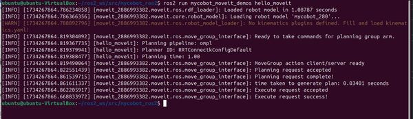
1-run-the-program

You can safely ignore this warning:

[WARN] [1734267864.788892796] [moveit_2886993382.moveit.ros.robot_model_loader]: No kinematics plugins defined. Fill and load kinematics.yaml!

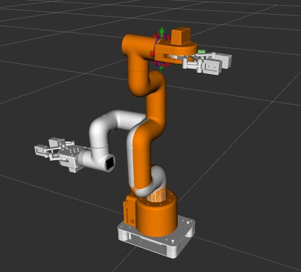
If everything is set up correctly, you should see the robot move in RViz to the specified pose.

2-move-in-rviz-to-the-pose

You can confirm the gripper is in the correct pose by typing the following command and comparing it to the pose you set in your hello_moveit.cpp file.

ros2 run tf2_ros tf2_echo base_link gripper_base

Note: If you run the hello_moveit node without first launching the demo launch file, it will wait for 10 seconds and then exit with an error message. This is because the MoveGroupInterface looks for a node publishing the robot description topic, which is provided by the demo launch file.

Let’s break down the key components of our hello_moveit.cpp file to understand how it works with MoveIt 2 for controlling the arm.

MoveGroupInterface Creation:

This part sets up a control interface for the robot’s arm. It’s like creating a special remote control that lets us send commands to move the arm.

Setting the Target Pose:

Here, we’re telling the arm where we want it to go. 

Planning the Motion:

This is where the robot figures out how to move from its current position to the target we set. It’s like planning a route on a map – the robot calculates all the steps needed to get from point A to point B safely.

Executing the Plan:

Finally, if the planning was successful, we tell the robot to actually perform the movement we planned. If the planning failed for some reason, we just report an error instead of trying to move.

These steps work together to allow us to control the robot arm in a safe and precise manner, moving it to exactly where we want it to go.

That’s it! Keep building.