
In this tutorial, we will create a Cartesian path planning demo from scratch using the MoveIt Task Constructor. This demo showcases how to plan a series of movements for a robotic arm in Cartesian space, including linear motions, rotations, and joint movements. Here is what you will create:
cartesian.cpp demonstrates a sequence of planned movements:
- Straight-line movements of the arm’s gripper (end-effector) relative to the base_link coordinate frame:
- 5 cm in the positive x direction
- 2 cm in the negative y direction
- A twisting movement of the arm relative to the base_link coordinate frame:
- 18-degree rotation around the z-axis
- Moving specific joints of the arm by absolute amounts:
- Rotating “link1_to_link2” joint by 15 degrees
- Rotating “link3_to_link4” joint by -15 degrees
- Returning to the starting “ready” position smoothly
Real-World Use Cases
The code you will develop in this tutorial can serve as a template for various practical applications:
- Pick and Place Operations
- Precise linear movements for accurate object placement
- Rotation capabilities for orienting objects correctly
- Assembly Tasks
- Combine linear motions and rotations for complex assembly procedures
- Fine-tune joint movements for intricate manipulations
- Welding or Painting
- Use linear movements to follow seams or contours
- Maintain consistent orientation during the process
Prerequisites
- You have completed this tutorial.
All the code is here on my GitHub repository. Note that I am working with ROS 2 Iron, so the steps might be slightly different for other versions of ROS 2.
Create the Code
Open a new terminal window, and type:
cd ~/ros2_ws/src/mycobot_ros2/hello_moveit_task_constructor/src/gedit cartesian.cppAdd this code.
/**
 * @file cartesian.cpp
 * @brief Demonstrates Cartesian path planning using MoveIt Task Constructor
 *
 * This program shows how to use MoveIt Task Constructor to plan a series of
 * movements for a robot arm. It includes linear motions, rotations, and joint
 * movements, all planned in Cartesian space.
 *
 * @author Addison Sears-Collins
 * @date August 16, 2024
 */

#include <moveit/task_constructor/task.h>
#include <moveit/task_constructor/stages/fixed_state.h>
#include <moveit/task_constructor/solvers/cartesian_path.h>
#include <moveit/task_constructor/solvers/joint_interpolation.h>
#include <moveit/task_constructor/stages/move_to.h>
#include <moveit/task_constructor/stages/move_relative.h>
#include <moveit/task_constructor/stages/connect.h>
#include <rclcpp/rclcpp.hpp>
#include <moveit/planning_scene/planning_scene.h>

// Use the moveit::task_constructor namespace to avoid typing it out each time
using namespace moveit::task_constructor;

/**
 * @brief Creates a Task Constructor task for Cartesian path planning.
 *
 * This function sets up a series of movements (called stages) for the robot to follow.
 * Each stage represents a specific motion, like moving in a straight line or rotating.
 * Logging statements are added to track the creation and addition of each stage.
 *
 * @param node A shared pointer to a ROS 2 node, used for accessing ROS functionality
 * @return Task The configured Task Constructor task, ready to be planned and executed
 */
Task createTask(const rclcpp::Node::SharedPtr& node) {

  // Create a new Task object
  Task t;

  // Set a name for the task (useful for debugging and visualization)
  t.stages()->setName("Cartesian Path");

  RCLCPP_INFO(node->get_logger(), "Creating Cartesian Path task");

  // Define the names of the robot's planning groups as defined in the SRDF
  const std::string arm = "arm";
  const std::string arm_with_gripper = "arm_with_gripper";

  // Create solvers for Cartesian and joint interpolation
  // Solvers are algorithms that figure out how to move the robot
  auto cartesian_interpolation = std::make_shared<solvers::CartesianPath>();
  auto joint_interpolation = std::make_shared<solvers::JointInterpolationPlanner>();

  RCLCPP_INFO(node->get_logger(), "Created Cartesian and Joint interpolation solvers");

  // Load the robot model (this contains information about the robot's structure)
  t.loadRobotModel(node);
  RCLCPP_INFO(node->get_logger(), "Loaded robot model");

  // Create a planning scene (this represents the robot and its environment)
  auto scene = std::make_shared<planning_scene::PlanningScene>(t.getRobotModel());
  RCLCPP_INFO(node->get_logger(), "Created planning scene");

  // Set the initial state of the robot
  {
    RCLCPP_INFO(node->get_logger(), "Setting initial state");

    // Get the current state of the robot and modify it
    auto& state = scene->getCurrentStateNonConst();

    // Set the robot arm to its "ready" position as defined in the SRDF
    state.setToDefaultValues(state.getJointModelGroup(arm_with_gripper), "ready");

    // Create a FixedState stage to represent this initial state
    auto fixed = std::make_unique<stages::FixedState>("initial state");
    fixed->setState(scene);

    // Add this stage to the task
    t.add(std::move(fixed));
    RCLCPP_INFO(node->get_logger(), "Added initial state to task");
  }

  // Stage 1: Move 0.05 meters in the positive x direction relative to the base_link frame
  {
    RCLCPP_INFO(node->get_logger(), "Creating stage: Move 0.05m in +x direction");

    // Create a MoveRelative stage using Cartesian interpolation
    auto stage = std::make_unique<stages::MoveRelative>("x +0.05", cartesian_interpolation);

    // Specify which group of joints to move
    stage->setGroup(arm);

    // Set the Inverse Kinematic frame to the end-effector
    stage->setIKFrame("link6_flange");

    // Create a Vector3Stamped message to specify the direction of movement
    geometry_msgs::msg::Vector3Stamped direction;

    // Set the frame of reference for this movement (the "base_link" frame)
    direction.header.frame_id = "base_link";

    // Set the x component to 0.05 meters (move 5 cm in the x direction)
    direction.vector.x = 0.05;

    // Set this direction as the movement for this stage
    stage->setDirection(direction);

    // Add this stage to the task
    t.add(std::move(stage));
    RCLCPP_INFO(node->get_logger(), "Added +x movement stage to task");
  }

  // Stage 2: Move 0.02 meters in the negative y direction relative to the base_link frame
  {
    RCLCPP_INFO(node->get_logger(), "Creating stage: Move 0.02m in -y direction");

    // Similar to the previous stage, but moving in the y direction
    auto stage = std::make_unique<stages::MoveRelative>("y -0.02", cartesian_interpolation);

    stage->setGroup(arm);
    stage->setIKFrame("link6_flange");

    geometry_msgs::msg::Vector3Stamped direction;
    direction.header.frame_id = "base_link";

    // Set the y component to -0.02 meters (move 2 cm in the negative y direction)
    direction.vector.y = -0.02;
    stage->setDirection(direction);

    t.add(std::move(stage));
    RCLCPP_INFO(node->get_logger(), "Added -y movement stage to task");
  }

  // Stage 3: Rotate 18 degrees around the z-axis of the base_link frame
  {
    RCLCPP_INFO(node->get_logger(), "Creating stage: Rotate -18 degrees around z-axis");

    auto stage = std::make_unique<stages::MoveRelative>("rz -18°", cartesian_interpolation);
    stage->setGroup(arm);
    stage->setIKFrame("link6_flange");

    // Create a TwistStamped message to specify a rotation
    geometry_msgs::msg::TwistStamped twist;
    twist.header.frame_id = "base_link";

    // Set the angular z component to -pi/10 radians (-18 degrees)
    twist.twist.angular.z = -M_PI / 10.;

    stage->setDirection(twist);
    t.add(std::move(stage));
    RCLCPP_INFO(node->get_logger(), "Added rotation stage to task");
  }

  // Stage 4: Move specific joints by specified angles
  {
    RCLCPP_INFO(node->get_logger(), "Creating stage: Move joints by specified angles");
    auto stage = std::make_unique<stages::MoveRelative>("joint offset", cartesian_interpolation);
    stage->setGroup(arm);

    // Create a map of joint names to angle offsets
    std::map<std::string, double> offsets = {
      { "link1_to_link2", M_PI / 12. },  // Rotate this joint by 15 degrees (pi/12 radians)
      { "link3_to_link4", -M_PI / 12. }   // Rotate this joint by -15 degrees
    };

    stage->setDirection(offsets);


    t.add(std::move(stage));
    RCLCPP_INFO(node->get_logger(), "Added joint offset stage to task");
  }

  // Stage 5: Connect the previous stages using joint interpolation
  // This stage ensures smooth transitions between all the previous stages and from the
  // previous stage to the final stage.
  {
    RCLCPP_INFO(node->get_logger(), "Creating connect stage");

    // Create a vector of groups and their associated planners
    stages::Connect::GroupPlannerVector planners = { { arm, joint_interpolation } };

    // Create a Connect stage to smoothly link the previous stages
    auto connect = std::make_unique<stages::Connect>("connect", planners);
    t.add(std::move(connect));
    RCLCPP_INFO(node->get_logger(), "Added connect stage to task");
  }

  // Set the final state of the robot
  {
    RCLCPP_INFO(node->get_logger(), "Setting final state");

    // The final state is the same as the initial state
    auto fixed = std::make_unique<stages::FixedState>("final state");
    fixed->setState(scene);
    t.add(std::move(fixed));
    RCLCPP_INFO(node->get_logger(), "Added final state to task");
  }

  // Return the fully configured task
  RCLCPP_INFO(node->get_logger(), "Task creation completed");
  return t;
}

/**
 * @brief Main function to demonstrate Cartesian path planning.
 *
 * This function initializes ROS 2, creates a node, sets up the task,
 * plans it, and attempts to execute it. Logging statements are added
 * to track the program's progress and any errors that occur.
 *
 * @param argc Number of command-line arguments
 * @param argv Array of command-line arguments
 * @return int Exit status (0 for success, non-zero for failure)
 */
int main(int argc, char** argv) {

  // Initialize ROS 2
  rclcpp::init(argc, argv);

  // Create a ROS 2 node named "cartesian_demo"
  auto node = rclcpp::Node::make_shared("cartesian_demo");

  RCLCPP_INFO(node->get_logger(), "Starting Cartesian path planning demo");

  // Start a separate thread to handle ROS 2 callbacks
  // This allows the node to process incoming messages and services
  std::thread spinning_thread([node] {
    RCLCPP_INFO(node->get_logger(), "Started ROS 2 spinning thread");
    rclcpp::spin(node);
  });

  // Create the task using our createTask function
  RCLCPP_INFO(node->get_logger(), "Creating task");
  auto task = createTask(node);

  // Attempt to plan and execute the task
  try {
    RCLCPP_INFO(node->get_logger(), "Attempting to plan task");

    // If planning succeeds...
    if (task.plan()) {
      RCLCPP_INFO(node->get_logger(), "Task planning succeeded");

      // ...publish the solution so it can be visualized or executed
      task.introspection().publishSolution(*task.solutions().front());
      RCLCPP_INFO(node->get_logger(), "Published task solution");

    } else {
      RCLCPP_ERROR(node->get_logger(), "Task planning failed");
    }
  } catch (const InitStageException& ex) {

    // If planning fails, print an error message
    RCLCPP_ERROR(node->get_logger(), "Planning failed with exception: %s", ex.what());
    RCLCPP_ERROR(node->get_logger(), "Task name: %s", task.name().c_str());
  }

  RCLCPP_INFO(node->get_logger(), "Waiting for ROS 2 spinning thread to finish");

  // Keeps the program running so that you can inspect the results in RViz
  spinning_thread.join();

  RCLCPP_INFO(node->get_logger(), "Cartesian path planning demo completed");

  // Exit the program
  return 0;
}
Save the file, and close it.
Build the Code
cd ~/ros2_ws/colcon buildsource ~/.bashrc
(OR source ~/ros2_ws/install/setup.bash if you haven’t set up your bashrc file to source your ROS distribution automatically with “source ~/ros2_ws/install/setup.bash”)Launch
Open two terminal windows, and run the following commands to launch our standard MoveIt 2 environment:
ros2 launch mycobot_gazebo mycobot_280_arduino_bringup_ros2_control_gazebo.launch.py use_rviz:=falseros2 launch hello_moveit_task_constructor demo.launch.pyNow run the demo:
ros2 launch hello_moveit_task_constructor run.launch.py exe:=cartesianHere is what you should see:
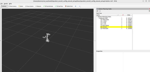
Understanding the Motion Planning Results
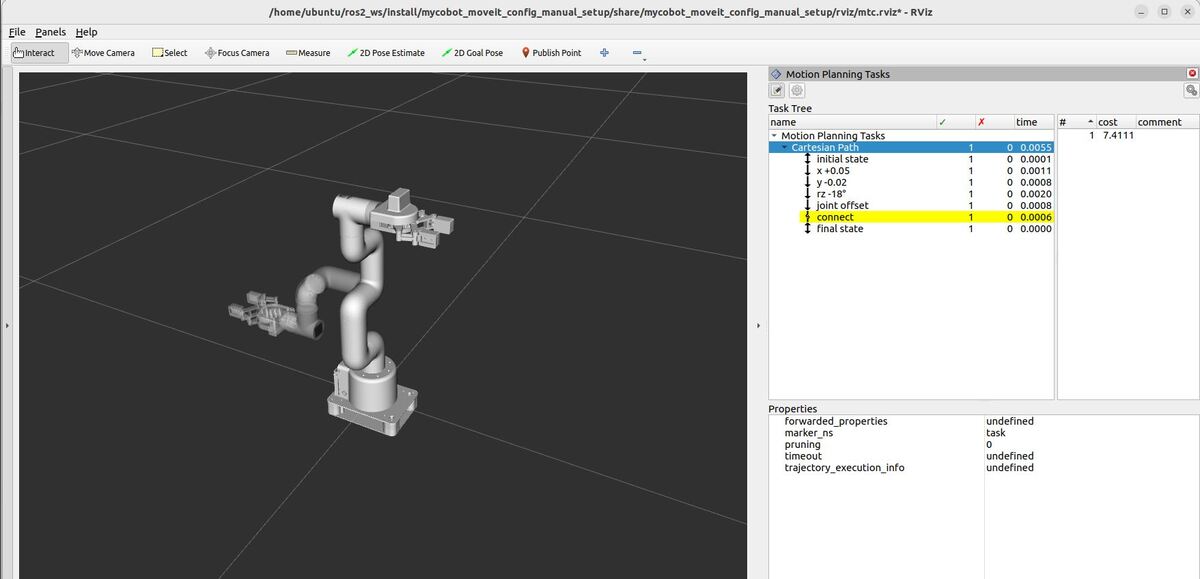
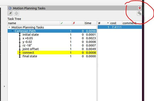
RViz – “Motion Planning Tasks” Panel
When running this demo, you’ll see a panel labeled “Motion Planning Tasks” on your screen. This panel shows the structure of each task. Clicking on a stage in this panel will display its outcomes – both successful and failed – in another window. You can then select and visualize individual solutions.
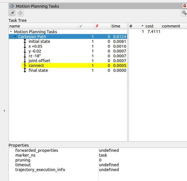
The Task Tree in the panel reflects the structure of our program. At the top, you’ll see “Motion Planning Tasks” with “Cartesian Path” underneath. This corresponds to our main task, which is designed to plan a series of Cartesian movements for the robot arm.
The task is divided into seven stages:
- “initial state”: Sets the starting position of the robot.
- “x +0.05”: Moves the end-effector 5 cm in the positive x direction.
- “y -0.02”: Moves the end-effector 2 cm in the negative y direction.
- “rz -18°”: Rotates the end-effector 18 degrees around the z-axis.
- “joint offset”: Adjusts specific joint angles.
- “connect”: Ensures smooth transitions between all the previous stages.
- “final state”: Sets the ending position of the robot.
The “connect” stage is where the magic happens. In our code, we’ve created a Connect stage to smoothly link the previous stages using joint interpolation.
The green checkmarks and numbers in the second column indicate how many successful solutions were found for each part of the task. For instance, if you see a “1” next to each stage, it means our planner successfully found a solution for each movement.
The rightmost column in the Task Tree displays the planning time for each component in seconds. This helps us understand which movements might be more computationally intensive.
As you experiment with the demo, try clicking on the different stages under the Task Tree and then click the line in the right-most column of the Motion Planning Tasks panel. You’ll be able to visualize how each stage contributes to the overall motion of the robot arm, helping you understand the progression of movements in Cartesian space.
Executing the Plan
If you want to execute the entire planned motion, you can use the “Execute” button in your control interface.
If everything worked fine during execution, you will see this line in the terminal window:
[moveit_ros.trajectory_execution_manager]: Completed trajectory execution with status SUCCEEDED ...Detailed Code Walkthrough
Now for the C++ part. Let’s go through each piece of this code, step by step.
cd ~/ros2_ws/src/mycobot_ros2/hello_moveit_task_constructor/src/gedit cartesian.cppFile Header and Includes
The code begins with a comprehensive comment block outlining the file’s purpose: demonstrating Cartesian path planning using MoveIt Task Constructor. It describes the program’s functionality, which includes planning linear motions, rotations, and joint movements in Cartesian space for a robotic arm. The file includes necessary headers for ROS 2, MoveIt, and the Task Constructor library, establishing the foundation for our Cartesian path planning demo.
createTask Function
This function is responsible for setting up the Task Constructor task with various stages of movement. Let’s break it down…
Task and Solver Setup
A Task object is created and named “Cartesian Path”. Two solvers are set up: one for Cartesian path planning and another for joint interpolation. These solvers will be used in different stages of the task.
Robot Model and Planning Scene Setup
The robot model is loaded, and a planning scene is created. This part sets up the environment in which the robot will operate.
Initial State Setup
The initial state of the robot is set to the “ready” position, and this state is added as the first stage of the task.
Movement Stages
The function then sets up several movement stages:
- Move 0.05m in +x direction
- Move 0.02m in -y direction
- Rotate -18 degrees around z-axis
- Move specific joints by specified angles
Each of these stages is created using stages::MoveRelative, configured with the appropriate movement parameters, and added to the task.
Connect Stage
A Connect stage is added to ensure smooth transitions between all the previous stages.
Final State
The final state is set to be the same as the initial state, completing the movement cycle.
Main Function
The main function orchestrates the entire demo.
ROS 2 Initialization and Node Setup
ROS 2 is initialized, and a node named “cartesian_demo” is created.
Spinning Thread
A separate thread is created to handle ROS 2 callbacks, allowing the node to process incoming messages and services.
Task Creation and Execution
The task is created using the createTask function. The code then attempts to plan the task. If planning succeeds, the solution is published for visualization or execution.
Error Handling
The code includes error handling to catch and report any exceptions that occur during the planning process.
Completion
The program waits for the ROS 2 spinning thread to finish, allowing for inspection of the results in RViz before exiting.
That’s it! Keep building!